
Recommended
More Related Content
What's hot
What's hot (20)
Similar to GM 4T40E Transmission Solenoid and Pressure Switch Test Settings
Similar to GM 4T40E Transmission Solenoid and Pressure Switch Test Settings (20)
Recently uploaded
Recently uploaded (20)
GM 4T40E Transmission Solenoid and Pressure Switch Test Settings
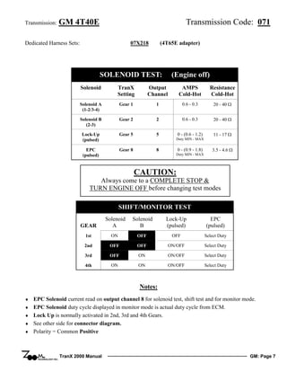
- 1. Transmission: GM 4T40E Transmission Code: 071 Dedicated Harness Sets: 07X218 (4T65E adapter) SOLENOID TEST: (Engine off) Solenoid TranX Setting Output Channel AMPS Cold-Hot Resistance Cold-Hot Solenoid A (1-2/3-4) Gear 1 1 0.6 - 0.3 20 - 40 Ω Solenoid B (2-3) Gear 2 2 0.6 - 0.3 20 - 40 Ω Lock-Up (pulsed) Gear 5 5 0 - (0.6 - 1.2) 11 - 17 Ω EPC (pulsed) Gear 8 8 Duty MIN - MAX 0 - (0.9 - 1.8) Duty MIN - MAX 3.5 - 4.6 Ω CAUTION: Always come to a COMPLETE STOP & TURN ENGINE OFF before changing test modes SHIFT/MONITOR TEST GEAR Solenoid A Solenoid B Lock-Up (pulsed) EPC (pulsed) 1st ON OFF OFF Select Duty 2nd OFF OFF ON/OFF Select Duty 3rd OFF ON ON/OFF Select Duty 4th ON ON ON/OFF Select Duty Notes: ♦ ♦ ♦ ♦ ♦ EPC Solenoid current read on output channel 8 for solenoid test, shift test and for monitor mode. EPC Solenoid duty cycle displayed in monitor mode is actual duty cycle from ECM. Lock Up is normally activated in 2nd, 3rd and 4th Gears. See other side for connector diagram. Polarity = Common Positive TranX 2000 Manual GM: Page 7
- 2. Transmission: GM 4T40E Pressure Switch Settings TOT Sensor Testing Gear Range A (Sensor 1) Range B (Sensor 2) Range C (Sensor 3) Park GREEN Red Red Resistance Temperature Reverse GREEN Red GREEN 2981 - 4018 Ω 68° F Neutral GREEN Red Red 1915 - 2550 Ω 86° F 1260 - 1660 Ω 104° F 848.8 - 1105 Ω 122° F 584.1 - 753.4 Ω 140° F 410.3 - 524.2 Ω 158° F 293.7 - 371.7 Ω 176° F 213.9 - 268.2 Ω 194° F 158.1 - 196.8 Ω 212° F Drive (1 to 4) GREEN GREEN Red Manual 3 Red GREEN Red Manual 2 Red GREEN GREEN Manual 1 GREEN GREEN GREEN Connect Multimeter to Sensor Module Test Points 5 & 6 CONNECTOR: (Looking into harness connector) D C B A E S R P N M L V U T Wiring Chart Case Connector Pin Number TranX 2000 Harness Wire Vehicle Function TranX 2000 Output Location TranX 2000 25 Way Pin A Blue Solenoid A Channel 1 7 B Green Solenoid B Channel 2 8 C Yellow EPC Power Channel 7 1 D Gray EPC Ground Channel 8 2 E Red,or Red/Brown Power to Solenoids L Red/Blue Stripe TOT Sensor Sensor 5 Test Point 19 M White/Red Stripe TOT Sensor Sensor 6 Test Point 20 N Orange Pressure Switch (A) Sensor LED 1 15 P Light Green Pressure Switch (C) Sensor LED 3 17 R White Pressure Switch (B) Sensor LED 2 16 S Pink 3-2 Control Solenoid Channel 3 5 T Purple Lockup Solenoid Channel 6 4 U Brown TCC Release Sensor 4 Test Point 18 V White/Green Speed Sensor Sensor 8 Test Point 22 TranX 2000 Manual 12 or 13 GM: Page 8