Network virtualization beyond vla ns-part1
•Download as DOCX, PDF•
0 likes•344 views

Network virtualization beyond VLANs...More details...

Recommended
More Related Content
What's hot
What's hot (18)
Viewers also liked
Viewers also liked (10)
Similar to Network virtualization beyond vla ns-part1
Similar to Network virtualization beyond vla ns-part1 (20)
More from IT Tech
More from IT Tech (20)
Recently uploaded
Recently uploaded (20)
Network virtualization beyond vla ns-part1
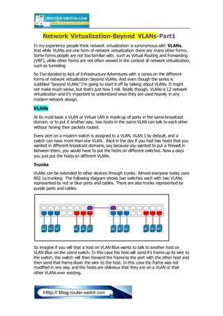
- 1. Network Virtualization-Beyond VLANs-Part1 In my experience people think network virtualization is synonymous with VLANs. And while VLANs are one form of network virtualization there are many other forms. Some forms people are not too familiar with, such as Virtual Routing and Forwarding (VRF), while other forms are not often viewed in the context of network virtualization, such as tunneling. So I’ve decided to kick of Infrastructure Adventures with a series on the different forms of network virtualization beyond VLANs. And even though the series is subtitled “beyond VLANs” I’m going to start it off by talking about VLANs. It might not make much sense, but that’s just how I roll. Really though, VLANs is L2 network virtualization and it’s important to understand since they are used heavily in any modern network design. VLANs At its most basic a VLAN or Virtual LAN is made up of ports in the same broadcast domain, or to put it another way, two hosts in the same VLAN can talk to each other without having their packets routed. Every port on a modern switch is assigned to a VLAN, VLAN 1 by default, and a switch can have more than one VLAN. Back in the day if you had two hosts that you wanted in different broadcast domains, say because you wanted to put a firewall in between them, you would have to put the hosts on different switches. Now a days you just put the hosts on different VLANs. Trunks VLANs can be extended to other devices through trunks. Almost everyone today uses 802.1q trunking. The following diagram shows two switches each with two VLANs represented by red or blue ports and cables. There are also trunks represented by purple ports and cables. So imagine if you will that a host on VLAN Blue wants to talk to another host on VLAN Blue on the same switch. In this case the host will send it’s frame up its wire to the switch, the switch will then forward the frame to the port with the other host and then send that frame down the wire to the host. In this case the frame was not modified in any way and the hosts are oblivious that they are on a VLAN or that other VLANs ever existing.
- 2. No imagine a host on VLAN Blue wants to talk with another host on VLAN Blue, but this time on the other switch. In this case the host will send it’s frame up its wire to the switch, but now the switch will have to forward it’s frame to the other switch to each it’s destination. When the switch forwards that frame out the port connected to the other switch it will need to “tag” the frame with a 802.1q header that specifies which VLAN that frame belongs to. So the frame is modified by inserting the 802.1q header and sent out the port connected to the other switch. The other switch receives the packet, examines the 802.1q header, sees which VLAN the frame belongs to and then forwards the frame to the appropriate port in VLAN blue. The frame is then sent down the cable to the destination host, without the 802.1q header. Again the hosts have no idea about the VLANs and the frame sent by one host is the exact frame received by the other. When dealing with VLANs there a few terms everyone should understand. A port assigned to a single VLAN is called an access port while a port configured as a trunk is called a trunk port, or uh … just a trunk. A frame with a 802.1q header is referred to as tagged. Subinterfaces As mentioned in part one, hosts in different VLANs cannot talk directly with each other since they are in different broadcast domains/subnets. For hosts on different VLANs to communicate with each other a layer 3 routing device is needed, usually a L3 Switch with an Switch Virtual Interface (SVI), a Router or a Firewall. The simplest way to route packets between two VLANs is by simply connecting a router with two physical interfaces to the switch. Each interface is connected to an access port on one of the VLANs.
- 3. With this method of Inter-VLAN routing you would need a router with a physical interface, cable, and switch port for each of the VLANs you need to connect. In some deployments this could be dozens, YUCK! Luckily we can use a trunk to allow the router to connect to multiple VLANs using a single port, similar to how two switches can be connected using a trunk. Since a router is a L3 device it is not configured with VLANs the same way as a switch. Although this can get fuzzy when you are talking about big advance routers or a router with a switch module, but let’s just focus on a regular branch router. Instead the router’s interface connected to the trunk will need to be configured with a subinterface, one for each VLAN that it is connecting. So in the following example the router’s interface connected to the switch would be configured with two subinterfaces, one for VLAN Red and one for VLAN Blue. Packets from VLAN Red would be sent up the trunk as tagged frames to the router. The router would see that the frame belongs to VLAN Red via the 802.1q header and would receive the packet on VLAN Red’s subinterface. The router would then route the packet and send it out VLAN Blue’s subinterface, tag the frame and send it back down the cable to the switch. In this deployment, referred to as a router on a stick (but can be firewall, load balancer, etc on a stick), the packets to or from the router use the same cable regardless of what VLAN the packets are going to or coming from. The main consideration for this type of design is capacity planning on the single cable. Since each packet transverses the cable twice, it effectively cuts the available bandwidth in half. This can be a serious consideration in larger deployments. To get around this issue you can use multiple physical interfaces each with a few subinterfaces, such as one interface having subinterfaces for VLANs Red and Blue and a second interfaces having subinterfaces for VLANs Green and Orange.
- 4. You could also just look at creating a Link Aggregation Group (LAG) of interfaces to add additional bandwidth to the “stick”, so instead of have VLANs Red & Blue on one interface and Green and Orange on another you can have all four VLANs on a single LAG of two or more interfaces. Configuring a subinterface on a Cisco router is pretty easy. Say for example that VLAN Red was VLAN number 10 and VLAN Blue was VLAN number 20 then the config would look something like this. GigabitEthernet1/0/0.10 Description Subinterface for VLAN Red ip address 10.10.10.1 255.255.255.0 encapsulation dot1q 10 GigabitEthernet1/0/0.20 Description Subinterface for VLAN Blue
- 5. ip address 10.10.20.1 255.255.255.0 encapsulation dot1q 20 Switch Virtual Interfaces (SVIs) We just talked about the network virtualization that was connecting layer 3 devices, such as routers, to multiple VLANs using subinterfaces. Subinterfaces allow a router to provide inter-VLAN routing with only a single interface. But what if we wanted to ditch the router completely? What about just having the switch do the inter-VLAN routing? This can be accomplished by configuring the switch with a Switch Virtual Interfaces (SVI) on each of the VLANs. Conceptually you can think of it as running a virtual router inside the switch. This virtual router is automatically configured with a trunk connecting it to all VLANs and the SVIs function as its subinterfaces. Using SVIs are pretty common nowadays and are usually used by L3 switches at the L2/L3 bounders of networks. Configuring an SVI is pretty simple: Interface vlan 10 Ip address 10.10.10.1 255.255.255.0 Interface vlan 20 Ip address 10.10.20.1 255.255.255.0 We often see confusion when configuring only a VLAN on a switch vs. configuring both a VLAN and a SVI. I think this often stems from the nebulous boundary between Layer 2 and Layer 3 on a switch. Remember that a VLAN is purely in Layer 2, hosts on one VLAN (L2) cannot talk to host on other VLAN without a router (L3). So if you want the switch to act as the router for a VLAN then you configure an SVI for that VLAN. If you just want the switch to act like a traditional switch for that VLAN then you do not configure an SVI for that VLAN. Whether the switch acts as a router for a VLAN is made on a VLAN by VLAN basis. A switch can have a SVI on some VLANs, acting as the router for those VLANs, and the same switch can have VLANs which it doesn’t have an SVI, where the switch does not act as a router for those VLAN. Usually a firewall or other non-router L3 devices are used to route packets to or from the VLANs without an SVI. A situation where it’s common to see switches with SVIs on some VLANs but not others are in a DMZ switch deployment. Consider the following diagram.
- 6. In this design we have two switches; switch 1 has VLANs 10, 100 and 200 with a SVI on each and switch 2 with VLANs 100, 110, 120, 200 and 210 with SVIs on VLAN 100, 110 and 120 (switch 2 does not have a SVI on any of the VLANs in the 200 range). A firewall is connected to switch 2 with one interface in VLAN 200 and the other in VLAN 210. In this design if host 110 wanted to talk to host 120, 110 would send a packet to the SVI on that VLAN and switch 2 would route the packet directly to VLAN 120. This is because switch 2 has SVIs on each of those VLANs and would have directly connected routes for these VLANs. But what if host 110 wanted to talk to host 210? Again 110 would send a packet to switch 2’s SVI on VLAN 110, but switch 2 could not route the packet directly to VLAN 210. This is because even though VLAN 210 is configured on switch 2, it does not have an SVI for that VLAN. Switch 2 has an L2 connection to that VLAN, but not an L3 connection. Instead switch 2 would have to route the packet on VLAN 100 via the trunk to switch 1. Switch 1 would then route the packet to VLAN 200 and send the packet to the firewall. The packet would be sent back over the trunk to switch 2, but switch 2 only acts as a normal run of the mill switch for that VLAN, so it only switches (L2) the packet (really the frame) to the port in VLAN 200 connected to the firewall.
- 7. The firewall received the packet, and then routes that packet out its interface connected to VLAN 210 on switch 2. Again switch 2 only just switches the packet on VLAN 210 to host 210. So in this design the packet between host 110 and 210 pass through switch 2 several times, but in some cases switch 2 routes the packets and in other cases switch 2 only switches the packet. This chosen design to make an example was not the most efficient design. Can you think of any changes to the design to improve the efficiency while keeping host 210 firewalled from the rest of the network? Tunnels Sometimes it is useful to connect two or more devices together when it would impossible or impractical to run a cable between them. Maybe they are on two different sides of the data center or two different sides of the country. In this case something like a virtual cable would be useful and a tunnel is a tool that can be used for the job. Simply speaking a tunnel is a network connection with payload consisting of other network traffic from the same OSI layer or lower. So for example an IP packet that is carrying another IP packet or an IP packet carrying an Ethernet frame would be a tunnel, while an IP packet carrying a TCP segment would just be a normal network connection. Basically a frame or packet enters a tunnel at one endpoint, “disappears” from the network, and “reappears” on the network at the other endpoint. Anatomy of a Network Tunnel A tunnel consists of four main parts, the network header for the tunnel, the tunnel header, the network header of the original Protocol Data Unit (PDU), and the data/payload of the original PDU. A PDU is encapsulated with the tunnel headers then the PDU enters the tunnel, and likewise the tunnel headers are stripped as the PDU leaves the tunnel.
- 8. Tunnel Network Header–This the original PDU is encapsulated in the tunnel this new network header is added. This header carries the source and destination addresses of the tunnel end points. The tunnel network header can consist of a header from a single layer or from multiple layers of the OSI model. For example a the tunnel network header for a GRE tunnel is just an IP header (L3) while the tunnel network header for a L2TP tunnel is both an IP and UDP header (L3 & L4). Tunnel Header–The tunnel header is a header specific to the tunneling protocol, so GRE, IPSec, L2TP and PPTP all have their own tunnel header format. Tunnel endpoints may have multiple tunnels between them and, among other things, the tunnel headers allows the end points to identify traffic from one tunnel or another. Original Network Header–This is the network header from the original PDU that is encapsulated in the tunnel. The original network header is usually not examined by network devices since it’s part of the tunnel’s payload, the same as any other payload data. Data–This is the payload of the original PDU. Tunnel Menagerie There are many many different types of tunnels but here are examples of a few different types of tunnels. Most people are familiar with IPSec tunnels which is our first example. IPSec is a classic example of a Layer 3 tunnel, where the original packet is encapsulated in a new IP packet with an IPSec tunnel header. Since this is a Layer 3 tunnel, the layer 2 Ethernet header is not touched and the same Ethernet header is used for both the original and new tunnel IP packet. IPSec is an example of a L3 tunnel, but if you need to tunnel L2 traffic over an L3 network then something like Layer 2 Tunneling Protocol (L2TP) can be used.
- 9. In the L2TP tunnel the entire frame, starting with the Ethernet header, is encapsulated in the new tunnel packet. Since the original Ethernet header is tunneled a new one is needed for the packet along with a new IP header. L2TP is an example of a tunnel protocol that uses uses multiple layers of the OSI to encapsulate it’s payload. It adds both a new IP header and a new UDP header using port 1701. Although sometimes a tunnel can’t offer all the functionality needed for a network connection, such as IPSec doesn’t support multicast, of the path between two tunnel end points might traverse another tunnel. In these cases tunnels maybe “stacked” sort of like a Russian doll of tunnels. For example you may have an IP Sec tunnel carrying a L2TP tunnel. In this case the you have the original frame encapsulated in a new frame with an L2TP packet which is then encapsulated in an IPSec Packet. I’ve run across plenty of people who have a hard time grasping the difference between L2 and L3, adding tunnels on tunnels can really turn things on their heads. Where is L3 in the packet above? It all depends on the context. So far we have covered traffic isolation, using VLANs or tunnels to keep traffic logically separated, in the next part I’ll start to cover virtualized routing and keeping different routing tables for your logically separated traffic. From http://infrastructureadventures.com/2010/11/19/network-virtualization- beyond-vlans-part-2-svis-and-subinterfaces/ …To be continued… More Related Topics VLAN vs. Subnet
- 10. ASA Routed vs. Transparent LANs vs. WANs