How to configure interior gateway routing protocol (igrp)
•Download as DOCX, PDF•
2 likes•1,702 views

The document describes how to configure Interior Gateway Routing Protocol (IGRP) on three routers to enable connectivity between three networks. It provides the configuration steps for each router, including setting hostnames, IP addresses on interfaces, and enabling IGRP with the network commands. It also shows how to verify the routing tables and connectivity between networks using the ping command.

Recommended
More Related Content
What's hot
What's hot (20)
Similar to How to configure interior gateway routing protocol (igrp)
Similar to How to configure interior gateway routing protocol (igrp) (20)
More from IT Tech
More from IT Tech (20)
How to configure interior gateway routing protocol (igrp)
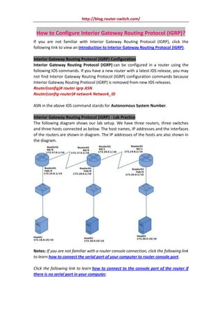
- 1. http://blog.router-switch.com/ How to Configure Interior Gateway Routing Protocol (IGRP)? If you are not familiar with Interior Gateway Routing Protocol (IGRP), click the following link to view an introduction to Interior Gateway Routing Protocol (IGRP). Interior Gateway Routing Protocol (IGRP) Configuration Interior Gateway Routing Protocol (IGRP) can be configured in a router using the following IOS commands. If you have a new router with a latest IOS release, you may not find Interior Gateway Routing Protocol (IGRP) configuration commands because Interior Gateway Routing Protocol (IGRP) is removed from new IOS releases. Router(config)# router igrp ASN Router(config-router)# network Network_ID ASN in the above IOS command stands for Autonomous System Number. Interior Gateway Routing Protocol (IGRP) - Lab Practice The following diagram shows our lab setup. We have three routers, three switches and three hosts connected as below. The host names, IP addresses and the interfaces of the routers are shown in diagram. The IP addresses of the hosts are also shown in the diagram. Notes: If you are not familiar with a router console connection, click the following link to learn how to connect the serial port of your computer to router console port. Click the following link to learn how to connect to the console port of the router if there is no serial port in your computer.
- 2. http://blog.router-switch.com/ Click the following links to learn how to use HyperTerminal terminal emulator and PuTTY terminal emulator to configure router. Hostname and IP address configuration in Router01 Connect to Router01 console and use the following IOS commands to configure host name as Router01. Router>enable Router#configure terminal Enter configuration commands, one per line. End with CNTL/Z. Router(config)#hostname Router01 Router01(config)# Use the following IOS commands to open the fast ethernet interface Fa0/0 configuration mode on Router01 and configure IP address as 172.16.0.1/16. Router01>enable Router01#configure terminal Enter configuration commands, one per line. End with CNTL/Z. Router01(config)#interface fa0/0 Router01(config-if)#ip address 172.16.0.1 255.255.0.0 Router01(config-if)#no shutdown Use the following IOS commands to open the serial interface S0/0 configuration mode on Router01 and configure IP address as 172.17.0.1/16. You have to set a clock rate also using the "clock rate" command on S0/0 interface, since this is the DCE side. Router01>enable Router01#configure terminal Enter configuration commands, one per line. End with CNTL/Z. Router01(config)#interface s0/0 Router01(config-if)#clock rate 64000 Router01(config-if)#ip address 172.17.0.1 255.255.0.0 Router01(config-if)#no shutdown Do remember to run the "copy running-config startup-config" command from enable mode, if you want to save the changes you have made in the router. Hostname and IP address configuration in Router02 Connect to Router02 console and use the following IOS commands to configure host name as Router02. Router>enable Router#configure terminal Enter configuration commands, one per line. End with CNTL/Z. Router(config)#hostname Router02 Router02(config)#
- 3. http://blog.router-switch.com/ Use the following IOS commands to open the fast ethernet interface Fa0/0 configuration mode on Router02 and configure IP address as 172.18.0.1/16. Router02>enable Router02#configure terminal Enter configuration commands, one per line. End with CNTL/Z. Router02(config)#interface fa0/0 Router02(config-if)#ip address 172.18.0.1 255.255.0.0 Router02(config-if)#no shutdown Use the following IOS commands to open the serial interface S0/0 configuration mode on Router02 and configure IP address as 172.17.0.2/16. Router02>enable Router02#configure terminal Enter configuration commands, one per line. End with CNTL/Z. Router02(config)#interface s0/0 Router02(config-if)#ip address 172.17.0.2 255.255.0.0 Router02(config-if)#no shutdown Use the following IOS commands to open the serial interface S0/1 configuration mode on Router02 and configure IP address as 172.19.0.1/16. You have to set a clock rate also using the "clock rate" command on S0/1 interface, since this is the DCE side. Router02>enable Router02#configure terminal Enter configuration commands, one per line. End with CNTL/Z. Router02(config)#interface s0/1 Router02(config-if)#clock rate 64000 Router02(config-if)#ip address 172.19.0.1 255.255.0.0 Router02(config-if)#no shutdown Do remember to run the "copy running-config startup-config" command from enable mode, if you want to save the changes you have made in the router. Hostname and IP address configuration in Router03 Connect to Router03 console and use the following IOS commands to configure host name as Router03. Router>enable Router#configure terminal Enter configuration commands, one per line. End with CNTL/Z. Router(config)#hostname Router03 Router03(config)# Use the following IOS commands to open the fast ethernet interface Fa0/0 configuration mode on Router03 and configure IP address as 172.20.0.1/16. Router03>enable
- 4. http://blog.router-switch.com/ Router03#configure terminal Enter configuration commands, one per line. End with CNTL/Z. Router03(config)#interface fa0/0 Router03(config-if)#ip address 172.20.0.1 255.255.0.0 Router03(config-if)#no shutdown Use the following IOS commands to open the serial interface S0/1 configuration mode on Router03 and configure IP address as 172.19.0.2/16. Router03>enable Router03#configure terminal Enter configuration commands, one per line. End with CNTL/Z. Router03(config)#interface s0/1 Router03(config-if)#ip address 172.19.0.2 255.255.0.0 Router03(config-if)#no shutdown Do remember to run the "copy running-config startup-config" command from enable mode, if you want to save the changes you have made in the router. Interior Gateway Routing Protocol (IGRP) configuration in Router01 Connect to Router01 console and use the following IOS commands to configure Interior Gateway Routing Protocol (IGRP) in Router01. Please refer the beginning of this lesson to view the Interior Gateway Routing Protocol (IGRP) configuration IOS command. In the IOS "network" command, shown below, we specify only the directly connected networks of this router. Router01>enable Router01#configure terminal Enter configuration commands, one per line. End with CNTL/Z. Router01(config)# router igrp 1 Router01(config-router)# network 172.16.0.0 Router01(config-router)# network 172.17.0.0 Router01(config-router)#exit Router01(config)#exit Router01# Do remember to run the "copy running-config startup-config" command from enable mode, if you want to save the changes you have made in the router. Interior Gateway Routing Protocol (IGRP) configuration in Router02 Connect to Router02 console and use the following IOS commands to configure Interior Gateway Routing Protocol (IGRP) in Router02. Please refer the beginning of this lesson to view the Interior Gateway Routing Protocol (IGRP) configuration IOS command.
- 5. http://blog.router-switch.com/ In the IOS "network" command, shown below, we specify only the directly connected networks of this router. Router02>enable Router02#configure terminal Enter configuration commands, one per line. End with CNTL/Z. Router02(config)# router igrp 1 Router02(config-router)# network 172.17.0.0 Router02(config-router)# network 172.18.0.0 Router02(config-router)# network 172.19.0.0 Router02(config-router)#exit Router02(config)#exit Router02# Do remember to run the "copy running-config startup-config" command from enable mode, if you want to save the changes you have made in the router. Interior Gateway Routing Protocol (IGRP) configuration in Router03 Connect to Router03 console and use the following IOS commands to configure Interior Gateway Routing Protocol (IGRP) in Router03. Please refer the beginning of this lesson to view the Interior Gateway Routing Protocol (IGRP) configuration IOS command. In the IOS "network" command, shown below, we specify only the directly connected networks of this router. Router03>enable Router03#configure terminal Enter configuration commands, one per line. End with CNTL/Z. Router03(config)# router igrp 1 Router03(config-router)# network 172.19.0.0 Router03(config-router)# network 172.20.0.0 Router03(config-router)#exit Router03(config)#exit Router03# Do remember to run the "copy running-config startup-config" command from enable mode, if you want to save the changes you have made in the router. How to View the Routing Table in Router01 After the network is converged after the initial configuration and Interior Gateway Routing Protocol (IGRP) configuration, we can use the "show ip route" to view the routing table in Router01, as shown below. Router01>enable Router01#show ip route
- 6. http://blog.router-switch.com/ Codes: C - connected, S - static, I - IGRP, R - RIP, M - mobile, B - BGP D - EIGRP, EX - EIGRP external, O - OSPF, IA - OSPF inter area N1 - OSPF NSSA external type 1, N2 - OSPF NSSA external type 2 E1 - OSPF external type 1, E2 - OSPF external type 2, E - EGP i - IS-IS, L1 - IS-IS level-1, L2 - IS-IS level-2, ia - IS-IS inter area * - candidate default, U - per-user static route, o - ODR P - periodic downloaded static route Gateway of last resort is not set C 172.16.0.0/16 is directly connected, FastEthernet0/0 C 172.17.0.0/16 is directly connected, Serial0/0 I 172.18.0.0/16 [120/1] via 172.17.0.2, 00:00:22, Serial0/0 I 172.19.0.0/16 [120/1] via 172.17.0.2, 00:00:22, Serial0/0 I 172.20.0.0/16 [120/2] via 172.17.0.2, 00:00:22, Serial0/0 The "I" character at the beginning of a line in routing table shows that it is a route discovered byInterior Gateway Routing Protocol (IGRP) and "C" character shows that it is a directly connected network. How to View the Routing Table in Router02? When the network is converged after the initial configuration and Interior Gateway Routing Protocol (IGRP) configuration, we can use the "show ip route" to view the routing table in Router02, as shown below. Router02>enable Router02#show ip route Codes: C - connected, S - static, I - IGRP, R - RIP, M - mobile, B - BGP D - EIGRP, EX - EIGRP external, O - OSPF, IA - OSPF inter area N1 - OSPF NSSA external type 1, N2 - OSPF NSSA external type 2 E1 - OSPF external type 1, E2 - OSPF external type 2, E - EGP i - IS-IS, L1 - IS-IS level-1, L2 - IS-IS level-2, ia - IS-IS inter area * - candidate default, U - per-user static route, o - ODR P - periodic downloaded static route Gateway of last resort is not set I 172.16.0.0/16 [120/1] via 172.17.0.1, 00:00:07, Serial0/0 C 172.17.0.0/16 is directly connected, Serial0/0 C 172.18.0.0/16 is directly connected, FastEthernet0/0 C 172.19.0.0/16 is directly connected, Serial0/1 I 172.20.0.0/16 [120/1] via 172.19.0.2, 00:00:20, Serial0/1 The "I" character at the beginning of a line in routing table shows that it is a route discovered by Interior Gateway Routing Protocol (IGRP) and "C" character shows that it is a directly connected network. How to View the Routing Table in Router03? When the network is converged after the initial configuration and Interior Gateway
- 7. http://blog.router-switch.com/ Routing Protocol (IGRP) configuration, we can use the "show ip route" to view the routing table in Router03, as shown below. Router03>enable Router03#show ip route Codes: C - connected, S - static, I - IGRP, R - RIP, M - mobile, B - BGP D - EIGRP, EX - EIGRP external, O - OSPF, IA - OSPF inter area N1 - OSPF NSSA external type 1, N2 - OSPF NSSA external type 2 E1 - OSPF external type 1, E2 - OSPF external type 2, E - EGP i - IS-IS, L1 - IS-IS level-1, L2 - IS-IS level-2, ia - IS-IS inter area * - candidate default, U - per-user static route, o - ODR P - periodic downloaded static route Gateway of last resort is not set I 172.16.0.0/16 [120/2] via 172.19.0.1, 00:00:02, Serial0/1 I 172.17.0.0/16 [120/1] via 172.19.0.1, 00:00:02, Serial0/1 I 172.18.0.0/16 [120/1] via 172.19.0.1, 00:00:02, Serial0/1 C 172.19.0.0/16 is directly connected, Serial0/1 C 172.20.0.0/16 is directly connected, FastEthernet0/0 The "I" character at the beginning of a line in routing table shows that it is a route discovered by Interior Gateway Routing Protocol (IGRP) and "C" character shows that it is a directly connected network. Verify the Connectivity between Networks Using the Ping Command To verify the Interior Gateway Routing Protocol (IGRP) routes and the connectivity between networks, run the ping command from Host01 (IP address: 172.16.0.10/16) to Host03 (IP address: 172.20.0.10/16). C:>ping 172.20.0.10 Pinging 172.20.0.10 with 32 bytes of data: Reply from 172.20.0.10: bytes=32 time=172ms TTL=125 Reply from 172.20.0.10: bytes=32 time=188ms TTL=125 Reply from 172.20.0.10: bytes=32 time=157ms TTL=125 Reply from 172.20.0.10: bytes=32 time=188ms TTL=125 Ping statistics for 172.20.0.10: Packets: Sent = 4, Received = 4, Lost = 0 (0% loss), Approximate round trip times in milli-seconds: Minimum = 157ms, Maximum = 188ms, Average = 176ms The ping reply from Host03 (IP address: 172.20.0.10/16) shows that the Interior Gateway Routing Protocol (IGRP) is configured well in three routers and there is network connectivity between different networks. ---Reference from http://www.omnisecu.com/cisco-certified-network-associate-ccna/how-to-configure- interior-gateway-routing-protocol-igrp.htm
- 8. http://blog.router-switch.com/ More Related Info and Guide: How to Configure IGRP (Interior Gateway Routing Protocol)?