SlideShare a Scribd company logo
1 of 5
Download to read offline
A.Y. Deogade, Dr. D.V. Bhope / International Journal of Engineering Research and
                     Applications (IJERA) ISSN: 2248-9622 www.ijera.com
                       Vol. 2, Issue 5, September- October 2012, pp.561-565
Investigation Of Effect Of Non Central Circular Holes On Stresses In
                            Rotating Disc
                                    A.Y. Deogade*, Dr. D.V. Bhope#
     *
         Student, IV Semester M.Tech (CAD/CAM) Mechanical Engineering Department, Rajiv Gandhi College of
                         Engg. Research & Technology, Chandrapur-442 401 (Maharashtra) (India)
                    #
                      Professor and Head Mechanical Engineering Department, Rajiv Gandhi College of
                         Engg. Research & Technology, Chandrapur-442 401 (Maharashtra) (India)


ABSTRACT
         In the present work the problem of               Element Method. The finite element approach is used
circular disc with a central hole and a                   to evaluate the stresses in the rotating disc with
symmetrical array of non-central holes subjected          central hole by varying R2/R1, d/2R1, Rb/ (R2-R1) and
to rotation are analyzed using Finite Element             number of holes (N) and to study the effect of
Method. The Stress Concentration Factors (SCF)            variation of these parameters in the stress
are derived for various geometric parameters like,        concentration factor in the disc.
R2/R1, d/2R1, Rb/ (R2-R1) and number of holes (N).
It is seen that, as the number of holes increases,        II. INTRODUCTION TO PROBLEM
the SCF decreases. The results are compared with                   In this project, effect of non central holes in
the analytical solution given by H.E.Ang and              disc with central hole is investigated considering
C.L.Tan1.                                                 various geometrical parameters of the disc. The disc
                                                          is shown in fig.1.
Keywords:       Disc, Non central hole, Stress            The various geometric parameter ratios & their
concentration, FEM                                        variation are as follows,
                                                          R2 / R1 = 3, 4, 5, 6, 7, 8, 9, 10
NOTATION                                                  d / 2R1 = 0.025, 0.05, 0.075, 0.1, 0.125, 0.15, 0.175,
A, B, C - positions at edges of holes shown in fig.1.     0.2, 0.225, 0.25
R1 - Radius of central hole (bore) of disc                Rb/(R2 – R1) = 0.1, 0.2, 0.3, 0.4, 0.5, 0.6, 0.7, 0.8, 0.9,
R2 - Outer radius of disc                                 1.0
Rb - Pitch circle radius of holes                         N = 4, 6, 8, 10, 12,14,16,18, 20, 24, 28, 32, 36, 40
d - Hole diameter                                                 The disc is made up of steel and its
N - Number of holes                                       mechanical properties are tabulated in Table.1.
E - Modulus of Elasticity
υ - Poisson’s ratio                                                  Table 1: Properties of Material
 ρ - Density of material                                  Modulus of Elasticity
                                                                                      E         200x103
 ω - Angular velocity of disc                             (MPa)
σθ - Hoop stress or tangential stress                     Poisson’s ratio             ν         0.3
σr - Radial stress                                        Density of      material
                                                                                      ρ         7800
(σθ)A - Hoop stress at point A                            (Kg/mm3)
(σθ)B - Hoop stress at point B

I. INTRODUCTION
          There are machines elements which rotate
while performing the required functions. These
include flywheels, thin rings, circular discs, pulley
rims, cylinders and spherical shells. Due to rotation,
centrifugal stresses are developed in these elements.
          Rotating disc shown in fig.1 found in           Fig.1. Circular disc with a central hole and a
numerous industrial applications. High centrifugal        symmetrical array of non-central holes
stresses, radial and hoop stresses occur at the non-
central holes needed to bolt discs together rotating at   III. LITERATURE REVIEW
high speed, such as compressor and turbine rotors of      i) Investigation by H.E. ANG and C.L. TAN,
aircraft engines, flywheel, gears, etc.                   Carleton University, Ottawa, Canada1
In the present work the problem of circular disc with              This paper studied the problem of a circular
a central hole and a symmetrical array of non-central     disc with a central hole and a symmetrical array of
holes subjected to rotation is analyzed by using Finite


                                                                                                   561 | P a g e
A.Y. Deogade, Dr. D.V. Bhope / International Journal of Engineering Research and
                   Applications (IJERA) ISSN: 2248-9622 www.ijera.com
                     Vol. 2, Issue 5, September- October 2012, pp.561-565
non-central holes subjected to rotation using the
boundary integral equation method.                        Figure 2 shows the typical variations of KA with the
          The aim of this paper is to present and         number of holes, N, for the different values of Rb,
highlight some features of the results for the local      considered: the variations for KB show identical
stresses at the edge of the non-central holes in thin     features. These trends were found to be true for all
circular discs subjected to rotation. The computed        the geometric cases and the loading conditions
stresses at these two points (σθ )A and (σθ)B, are        treated.
presented. For generality, they are expressed in
terms of stress factors KA, and KB, respectively. In               The tabulated coefficients can be
the case of disc rotation, they are defined as,           conveniently interpolated to obtain intermediate
                   KA = (σθ )A / σo                       values for the stress factors for discs which are within
            and KB = (σθ )B / σo                          the range of R2/R1, and Rb/(R2-R1) ratios and N
Where,                                                    considered for the values of N less than 20 as shown
             3+υ                    1+3υ                  in Table 2 and Table 3.
       σo = 8 ρω2 R2 + 2R2 − 3+υ R2
                        1      2          1      …. (1)
          is the hoop stress at the bore of a plane       Table 2: Coefficients of stress factor Equations,
disc with the same bore and outer radii as the            equation (3). For the case of disc rotation: d/2R1 =
problem treated; the material density, 𝜌, Poisson's       0.05
ratio, and speed of rotation are also having the same
values. For the results corresponding to the radial
tension load case,
            KA=(σθ )A/σ                  …………(2a)
     And KB=(σθ)B/σ                             ……(2b)

             KA= α − βN                  ……… (3a)
     KB = ξ − ηN ; 20 ≤ N ≤ 40           ………(3b)
          The coefficients 𝛼, 𝛽, 𝜉, 𝜂 so obtained are
listed in for all the cases treated. It should be
remarked that the values of K A and KB calculated
using equation and the tabulated coefficients,
deviated, in general, by less than 0.5 percent from
the corresponding BIE computed values.                    Table 3: Coefficients of stress factor Equations,
In terms of the ligament efficiency of the perforated     equation (3). For the case of disc rotation: d/2R1 =
part of the disc, , which may be defined as,              0.075
                      a-d
                   ∑= a                       …… (4)
         These values correspond to the following
ranges of ∑ for the respective radius ratios of the
disc: 0.3634-0.823 for R2/R1 = 2; 0.523-0.878 for
R2/R1 = 3; and 0.618-0.906 for R2/R1 = 4. For each
and every combination of the above set of geometric
parameter values, the stress distributions in the disc
were obtained for the load case of the disc rotating at
speed ω and subjected to uniform radial tension 𝜎 at
the outer periphery. Poisson's ratio, υ was taken to be
0.3 throughout.
                                                          ii)    Investigation     by     H.FESSLER          and
                                                          T.E.THORPE,          University    of    Nottingham,
                                                          Nottingham
                                                                    This paper studied the frozen stress photo
                                                          elastic technique to determine the hoop and radial
                                                          stresses at the hole boundaries of sixty different hole
                                                          configuration in flat discs. Rotating discs are
                                                          frequently required in engineering, but special
                                                          problems arise in gas turbine discs because these
                                                          rotate at high speeds and must be as light as possible.


Fig.2: Variation of KA with N; R2/R1=2, d/2R1=0.05


                                                                                                 562 | P a g e
A.Y. Deogade, Dr. D.V. Bhope / International Journal of Engineering Research and
                   Applications (IJERA) ISSN: 2248-9622 www.ijera.com
                     Vol. 2, Issue 5, September- October 2012, pp.561-565
iii) Investigation by CERLINCA Delia Aurora,                    5.5                                                               Rb/(R2-R1)
                                                                                                                                         0.6
University of Suceava
                                                                4.5                                                                      0.7
         The paper studied for an axially symmetrical
                                                                                                                                         0.8
disk, with or without a central hole; there are                 3.5                                                                      0.9


                                                         KA 
analytical relations between stresses, strains,                                                                                          1
depending on disk geometry and angular velocity. It             2.5
is known that the static condition a keyway induces             1.5
increased stresses acting as a stress concentrator.
                                                                0.5
iv) Investigation by H. FESSLER and T. E.                                       4           6      8      10 12 16      20   24
                                                                                                       No. of holes 
THORPE University of Nottingham, Nottingham
         This paper investigates the frozen-stress       Fig.7: Variation of SCF with Respect to Number of
photo elastic technique used to determine the stresses   Holes for R2/R1=3
around reinforced non-central holes in discs. Both
                                                                    4                                                             Rb/(R2-R1)
circular bosses and a thickened annulus were used as                                                                                     0.4
                                                                3.5
reinforcements. Calculations by Green, Hooper, and                                                                                       0.5
Hetherington were found to predict the mean stresses                3
                                                                                                                                         0.6
(through the thickness) well but these calculations             2.5                                                                      0.7


                                                         KA 
cannot predict the peak stresses. The latter were not               2                                                                    0.8
significantly less than the values of the unreinforced          1.5                                                                      0.9
perforated discs. The stresses in a taper disc were                 1                                                                    1
lower than in a disc of constant thickness.                     0.5
                                                                            4           6       8 10 12 16 20 24 28 32 36
                                                                                                   No. of Holes 
IV. VARIATION OF SCF WITH RESPECT
TO   GEOMETRICAL    PARAMETERS                              Fig.8: Variation of SCF with Respect to Number
                                                         of Holes for R2/R1=4
EVALUATED BY FE APPROACH
          Principal stress contours for some ratios
R2/R1, Rb/ (R2-R1), d/2R1, N are shown in fig.3 to                  3                                                             Rb/(R2-R1)
fig.6 as an illustration.                                                                                                                 0.3
                                                            2.5                                                                           0.4
                                                                                                                                          0.5
                                                                    2                                                                     0.6
                                                         KA 


                                                                                                                                          0.7
                                                            1.5
                                                                                                                                          0.8
                                                                    1                                                                     0.9
                                                                                                                                          1
                                                            0.5
Fig.3: Principal Stress      Fig.4: Principal Stress                        4           6   8 10 12 16 20 24 28 32 36 40
Contour (σθ) for R2/R1      Contour (σθ) for R2/R1=3,                                           No. of holes 
 =3, Rb/(R2-R1)=0.8,         Rb/(R2-R1)=0.9, d/2R1=        Fig.9: Variation of SCF with Respect to Number of
 d/2R1=0.2,N=24            0.225 , N=4                   Holes for R2/R1=5

                                                                2                                                                 Rb/(R2-R1)
                                                                                                                                         0.3
                                                          1.5                                                                            0.4
                                                                                                                                         0.5
                                                         KA 


                                                                                                                                         0.6
                                                                1                                                                        0.7
                                                                                                                                         0.8
                                                          0.5                                                                            0.9
                                                                                                                                         1
Fig.5: Principal Stress     Fig.6: Principal Stress             0
Contour (σθ) for R2/R1=    Contour (σθ) for R2/R1=4,                    4           6       8 10 12 16 20 24 28 32 36 40
                                                                                                 No. of holes 
4, Rb/(R2-R1)= 0.8,        Rb/(R2-R1)=1,d/2R1=0.25,       Fig.10: Variation of SCF with Respect to Number of
d/2R1=0.2, N=4             N=36                          Holes for R2/R1=6
  An effort is made to show the variation of SCF with
respect to geometrical parameter of disc         i, e,
Rb/(R2-R1), R2/R1, d/2R1 and number of holes (N).
These variations are shown in Fig.7 to Fig. 14.


                                                                                                                        563 | P a g e
A.Y. Deogade, Dr. D.V. Bhope / International Journal of Engineering Research and
                              Applications (IJERA) ISSN: 2248-9622 www.ijera.com
                                Vol. 2, Issue 5, September- October 2012, pp.561-565
           3                                             Rb/(R2-R1)   Table 4: Comparison of FE and Analytical Results for
                                                                0.2
      2.5                                                       0.3   d/2R1=0.05
                                                                0.4        R / (R2             σθ|FEM at
           2                                                           R2/ b       d/                  σθ|THEO.       KA|
KA 


                                                                0.5        (R2- Rb      d N pt. A              KA
                                                                0.6    R1          2R1                 (MPa)          The.$
      1.5
                                                                0.7        R1)                 (MPa)
           1                                                    0.8                        20 485.858 260.032 1.868 1.243
                                                                0.9                        24 498.441 260.032 1.916 1.220
      0.5                                                       1
                                                                                           28 471.526 260.032 1.813 1.197
                  4   6   8 10 12 16 20 24 28 32 36 40                     0.6 24 0.05 2
                              No. of holes                                                32 476.938 260.032 1.834 1.174
 Fig.11: Variation of SCF with Respect to Number of                                        36 460.247 260.032 1.769 1.151
Holes for R2/R1=7                                                                          40 460.83 260.032 1.772 1.128
                                                                                           20 464.486 260.032 1.786 1.163
          2.5                                            Rb/(R2-R1)                        24 436.965 260.032 1.680 1.143
                                                                0.2
                                                                0.3                        28 471.523 260.032 1.813 1.124
              2                                                        3 0.7 28 0.05 2
                                                                0.4                        32 414.451 260.032 1.593 1.104
                                                                0.5                        36 397.778 260.032 1.529 1.084
          1.5                                                   0.6
KA 


                                                                0.7                        40 390.733 260.032 1.502 1.065
              1                                                 0.8                        20 402.29 260.032 1.547 1.080
                                                                0.9
          0.5                                                   1                          24 397.121 260.032 1.527 1.063
                  4   6   8 10 12 16 20 24 28 32 36 40
                                                                                           28 373.352 260.032 1.435 1.047
                              No. of holes                                0.8 32 0.05 2
                                                                                           32 365.164 260.032 1.404 1.031
  Fig12: Variation of SCF with Respect to                                                  36 354.958 260.032 1.365 1.015
Number of Holes for R2/R1=8                                                                40 343.583 260.032 1.321 0.998
          2.5                                            Rb/(R2-R1)
                                                                0.2                        20 721.946 457.622 1.577 1.192
              2                                                 0.3                        24 699.263 457.622 1.528 1.176
                                                                           0.5 30 0.05 2
                                                                0.4                        28 706.564 457.622 1.543 1.160
 KA -->


          1.5
                                                                0.5                        32 714.737 457.622 1.561 1.143
              1                                                 0.6                        20 685.121 457.622 1.497 1.099
          0.5                                                   0.7                        24 625.976 457.622 1.367 1.086
                                                                0.8                        28 656.061 457.622 1.433 1.074
              0                                                 0.9        0.6 36 0.05 2
                                                                                           32 622.804 457.622 1.360 1.061
                   4 6 8 10 12 16 20 24 28 32 36 40             1
                           No. of Holes -->                                                36 602.582 457.622 1.316 1.049
 Fig.13: Variation of SCF with Respect to                                                  40 572.771 457.622 1.251 1.036
Number of Holes for R2/R1=9                                                                20 608.248 457.622 1.329 1.017
                                                                       4
                                                                                           24 599.54 457.622 1.310 1.007
   2.5                                                Rb/(R2-R1)                           28 560.41 457.622 1.224 0.997
                                                              0.2          0.7 42 0.05 2
          2
                                                                                           32 541.045 457.622 1.182 0.9876
                                                              0.3
                                                              0.4                          36 530.183 457.622 1.158 0.9778
   1.5                                                        0.5                          40 528.798 457.622 1.155 0.968
                                                              0.6                          20 552.879 457.622 1.208 0.9425
 KA 


          1                                                   0.7                          24 547.907 457.622 1.197 0.9342
                                                              0.8
   0.5
                                                              0.9
                                                                                           28 546.596 457.622 1.194 0.9260
                                                                           0.8 48 0.05 2
                  4   6   8 10 12 16 20 24 28 32 36 40        1                            32 537.205 457.622 1.173 0.9177
                                                                                           36 509.025 457.622 1.112 0.9095
                                                                                           40 490.968 457.622 1.072 0.9013
   Fig.14: Variation of SCF with Respect to
Number of Holes for R2/R1=10

V. COMPARISON OF FE RESULTS
WITH ANALYTICAL RESULTS REPORTED BY
H.E. ANG & C.L.TAN1
         The physical geometries and SCF given by
H.E.ANG and C.L.TAN1 and evaluated by FE approach are
given in Table 3 and Table 4 for the ratio of d/2R1=0.05 and
d/2R1=0.075


                                                                                                     564 | P a g e
A.Y. Deogade, Dr. D.V. Bhope / International Journal of Engineering Research and
                       Applications (IJERA) ISSN: 2248-9622 www.ijera.com
                         Vol. 2, Issue 5, September- October 2012, pp.561-565
    Table 5: Comparison of FE and Analytical Results for  The Stress Concentration Factors derived for various
    d/2R1=0.075                                           geometric parameters like, R2/R1, d/2R1, Rb/(R2-R1) and
    Rb/ (R2                σθ|FEM σθ| at                  number of holes (N) can serve as a guideline for designing
R2/           d/                                   KA|
    (R2- Rb        d N pt. A THEO. KA                 $   the perforated rotating disc.
R1            2R1                                 The.
    R1)-R1)                 (MPa) (MPa)
                      20 485.858 260.032 1.868452 1.2477 REFERENCES
    0.6 24 0.075 3
                      24 498.441 260.032 1.916842 1.2081   (1)     H.E.Ang and C.L.Tan, ‘Stress Concentration at
                      20 464.486 260.032 1.786262 1.153   Holes in Thin Rotating Discs’, Journal of Strain Analysis
3 0.7 28 0.075 3
                      24 436.965 260.032 1.680425 1.1174 Vol.23, No.4, P. No. 223-225,1988
                      20 402.29 260.032 1.547076  1.0751 (2)       FESSLER, H. and THORPE, T. E. ‘Optimization
    0.8 32 0.075 3                                        of Stress Concentrations in Rotating Discs’, Journal of
                      24 397.121 260.032 1.527198 1.0448
                      20 721.946 457.622 1.577601 1.1658 Strain Analysis, Vol.2, P.No.152-358,1967
                      24 699.263 457.622 1.528034 1.1362 (3)       FESSLER, H. and THORPE, T. E. ‘Reinforcement
    0.5 30 0.075 3                                        of Non-central Holes in Rotating Discs’, Journal of Strain
                      28 706.564 457.622 1.543988 1.1066
                      32 714.737 457.622 1.561847 1.0771 Analysis, Vol.2, P.No.317-323, 1967
                      20 685.121 457.622 1.49713  1.0778   (4)     H.E.Ang and C.L.Tan, ‘Stress Intensity Factors for
                                                          Cracks at Holes in Thin Rotating Discs’, International
                      24 625.976 457.622 1.367886 1.0548
    0.6 36 0.075 3                                        Journal of Fracture, 40, P.No.R3-R11, 1989.
                      28 656.061 457.622 1.433628 1.0318
                                                          (5)      TAN, C. L. and FENNER, R. T. ‘Elastic Fracture
                      32 622.804 457.622 1.360955 1.0089 Mechanics by the Boundary Integral Equation Method’,
4
                      20 608.248 457.622 1.329147 1.0009 Proc. R. Soc. Lond., A369, P. No. 243-260, 1979
                      24 599.54 457.622 1.310118  0.9811
    0.7 42 0.075 3
                      28 560.41 457.622 1.224611  0.9614
                      32 541.045 457.622 1.182295 0.9417
                      20 552.879 457.622 1.208154 0.9299
                      24 547.907 457.622 1.19729  0.9130
    0.8 48 0.075 3
                      28 546.596 457.622 1.194425 0.8962
                      32 537.205 457.622 1.173903 0.8793
    $ - Stress Concentration Factor reported by H.E. Ang and
    C.L. Tan.

              It is seen from the Table 4 & 5 that the SCF
    determined by FE approach and with analytical
    approach differ by 62 to 84%.This confirms that the
    analytical solution represented C.L.Tan and H.E.Ang may
    need some correction factors depend upon geometry of
    perforated disc. Hence, it can be suggested that the
    analytical approach may needs some refinement to
    predict the actual SCF in perforated disc.

    VI. DISCUSSION AND CONCLUSION
    1.        It is observed that as the number of holes
    increases the SCF decreases for most cases. But for
    some cases it is observed that the SCF increases
    abruptly after certain number of holes. This may be
    due to very less pitch width between the two
    consecutive holes. Thus there is a limit for the
    maximum number of holes to keep the working
    stresses within safe limits.
    2.        As it is also seen that as the pitch circle
    radius of non central holes increases, the SCF
    decreases. Thus the non central holes very close to
     the central hole should be avoided in practice.
    3.        As the diameter of non central holes
    increases the SCF decreases. This may be due to the
    smoothening of stress lines over larger curvature of
    hole. Thus larger diameter of non central hole is
     preferred in actual practice.


                                                                                               565 | P a g e

More Related Content

Viewers also liked (20)

Cq24604607
Cq24604607Cq24604607
Cq24604607
 
Co25535539
Co25535539Co25535539
Co25535539
 
Ct24621630
Ct24621630Ct24621630
Ct24621630
 
D25014017
D25014017D25014017
D25014017
 
Dp25687691
Dp25687691Dp25687691
Dp25687691
 
Dk25664666
Dk25664666Dk25664666
Dk25664666
 
Cx24645648
Cx24645648Cx24645648
Cx24645648
 
Bq25399403
Bq25399403Bq25399403
Bq25399403
 
Ce25481484
Ce25481484Ce25481484
Ce25481484
 
Bn26425431
Bn26425431Bn26425431
Bn26425431
 
Dp31778783
Dp31778783Dp31778783
Dp31778783
 
Iq2616601665
Iq2616601665Iq2616601665
Iq2616601665
 
Dc31712719
Dc31712719Dc31712719
Dc31712719
 
O sangue
O sangueO sangue
O sangue
 
FELIZ NAVIDAD
FELIZ NAVIDADFELIZ NAVIDAD
FELIZ NAVIDAD
 
Agenda politica economica version final
Agenda politica economica version finalAgenda politica economica version final
Agenda politica economica version final
 
Prova de raciocinio logico fevereiro 2005
Prova  de raciocinio logico fevereiro 2005Prova  de raciocinio logico fevereiro 2005
Prova de raciocinio logico fevereiro 2005
 
Biologia
BiologiaBiologia
Biologia
 
Call for a Transformational Process in the face of Climate Change
Call for a Transformational Process in the face of Climate ChangeCall for a Transformational Process in the face of Climate Change
Call for a Transformational Process in the face of Climate Change
 
Diplôme ICI
Diplôme ICIDiplôme ICI
Diplôme ICI
 

Similar to Effect of Non-Central Holes on Rotating Disc Stresses

Composite dome Shape and Pressure Vessels Optimization
Composite dome Shape and Pressure Vessels OptimizationComposite dome Shape and Pressure Vessels Optimization
Composite dome Shape and Pressure Vessels Optimizationalilimam2
 
3 d analysis of stress concentration factor and
3 d analysis of stress concentration factor and3 d analysis of stress concentration factor and
3 d analysis of stress concentration factor andIAEME Publication
 
techDynamic characteristics and stability of cylindrical textured journal bea...
techDynamic characteristics and stability of cylindrical textured journal bea...techDynamic characteristics and stability of cylindrical textured journal bea...
techDynamic characteristics and stability of cylindrical textured journal bea...ijmech
 
Finite Element Analysis - UNIT-3
Finite Element Analysis - UNIT-3Finite Element Analysis - UNIT-3
Finite Element Analysis - UNIT-3propaul
 
Simulation of geometrical cross
Simulation of geometrical crossSimulation of geometrical cross
Simulation of geometrical crossprjpublications
 
Study on the Effect of Stress Concentration on Cutout Orientation of Plates w...
Study on the Effect of Stress Concentration on Cutout Orientation of Plates w...Study on the Effect of Stress Concentration on Cutout Orientation of Plates w...
Study on the Effect of Stress Concentration on Cutout Orientation of Plates w...IJMER
 
Computational buckling of a three lobed crosection cylindrical shell with var...
Computational buckling of a three lobed crosection cylindrical shell with var...Computational buckling of a three lobed crosection cylindrical shell with var...
Computational buckling of a three lobed crosection cylindrical shell with var...prjpublications
 
Free Vibration Analysis of circular plates with holes and cutouts
Free Vibration Analysis of circular plates with holes and cutoutsFree Vibration Analysis of circular plates with holes and cutouts
Free Vibration Analysis of circular plates with holes and cutoutsIOSR Journals
 
Effect of cylindrical texture on dynamic characteristics of journal bearing
Effect of cylindrical texture on dynamic characteristics of journal bearingEffect of cylindrical texture on dynamic characteristics of journal bearing
Effect of cylindrical texture on dynamic characteristics of journal bearingijmech
 
Empirical relation to estimate the reduction of root fillet stress in spur ge...
Empirical relation to estimate the reduction of root fillet stress in spur ge...Empirical relation to estimate the reduction of root fillet stress in spur ge...
Empirical relation to estimate the reduction of root fillet stress in spur ge...eSAT Publishing House
 
Finite Element Analysis of Obround Pressure Vessels
Finite Element Analysis of Obround Pressure VesselsFinite Element Analysis of Obround Pressure Vessels
Finite Element Analysis of Obround Pressure VesselsIJMER
 
APPLICATION OF THE BOUNDARY ELEMENT METHOD IN DETERMINING THE CRITICAL BUCKLI...
APPLICATION OF THE BOUNDARY ELEMENT METHOD IN DETERMINING THE CRITICAL BUCKLI...APPLICATION OF THE BOUNDARY ELEMENT METHOD IN DETERMINING THE CRITICAL BUCKLI...
APPLICATION OF THE BOUNDARY ELEMENT METHOD IN DETERMINING THE CRITICAL BUCKLI...Engenheiro Civil
 

Similar to Effect of Non-Central Holes on Rotating Disc Stresses (20)

Composite dome Shape and Pressure Vessels Optimization
Composite dome Shape and Pressure Vessels OptimizationComposite dome Shape and Pressure Vessels Optimization
Composite dome Shape and Pressure Vessels Optimization
 
3 d analysis of stress concentration factor and
3 d analysis of stress concentration factor and3 d analysis of stress concentration factor and
3 d analysis of stress concentration factor and
 
techDynamic characteristics and stability of cylindrical textured journal bea...
techDynamic characteristics and stability of cylindrical textured journal bea...techDynamic characteristics and stability of cylindrical textured journal bea...
techDynamic characteristics and stability of cylindrical textured journal bea...
 
Finite Element Analysis - UNIT-3
Finite Element Analysis - UNIT-3Finite Element Analysis - UNIT-3
Finite Element Analysis - UNIT-3
 
Simulation of geometrical cross
Simulation of geometrical crossSimulation of geometrical cross
Simulation of geometrical cross
 
N24108113
N24108113N24108113
N24108113
 
Ball beaing
Ball beaingBall beaing
Ball beaing
 
Study on the Effect of Stress Concentration on Cutout Orientation of Plates w...
Study on the Effect of Stress Concentration on Cutout Orientation of Plates w...Study on the Effect of Stress Concentration on Cutout Orientation of Plates w...
Study on the Effect of Stress Concentration on Cutout Orientation of Plates w...
 
G012444549
G012444549G012444549
G012444549
 
Computational buckling of a three lobed crosection cylindrical shell with var...
Computational buckling of a three lobed crosection cylindrical shell with var...Computational buckling of a three lobed crosection cylindrical shell with var...
Computational buckling of a three lobed crosection cylindrical shell with var...
 
Free Vibration Analysis of circular plates with holes and cutouts
Free Vibration Analysis of circular plates with holes and cutoutsFree Vibration Analysis of circular plates with holes and cutouts
Free Vibration Analysis of circular plates with holes and cutouts
 
Effect of cylindrical texture on dynamic characteristics of journal bearing
Effect of cylindrical texture on dynamic characteristics of journal bearingEffect of cylindrical texture on dynamic characteristics of journal bearing
Effect of cylindrical texture on dynamic characteristics of journal bearing
 
Empirical relation to estimate the reduction of root fillet stress in spur ge...
Empirical relation to estimate the reduction of root fillet stress in spur ge...Empirical relation to estimate the reduction of root fillet stress in spur ge...
Empirical relation to estimate the reduction of root fillet stress in spur ge...
 
Finite Element Analysis of Obround Pressure Vessels
Finite Element Analysis of Obround Pressure VesselsFinite Element Analysis of Obround Pressure Vessels
Finite Element Analysis of Obround Pressure Vessels
 
APPLICATION OF THE BOUNDARY ELEMENT METHOD IN DETERMINING THE CRITICAL BUCKLI...
APPLICATION OF THE BOUNDARY ELEMENT METHOD IN DETERMINING THE CRITICAL BUCKLI...APPLICATION OF THE BOUNDARY ELEMENT METHOD IN DETERMINING THE CRITICAL BUCKLI...
APPLICATION OF THE BOUNDARY ELEMENT METHOD IN DETERMINING THE CRITICAL BUCKLI...
 
Eg34799802
Eg34799802Eg34799802
Eg34799802
 
Sdarticle 2
Sdarticle 2Sdarticle 2
Sdarticle 2
 
Sdarticle 2
Sdarticle 2Sdarticle 2
Sdarticle 2
 
Sdarticle 2
Sdarticle 2Sdarticle 2
Sdarticle 2
 
Solution manual 17 19
Solution manual 17 19Solution manual 17 19
Solution manual 17 19
 

Effect of Non-Central Holes on Rotating Disc Stresses

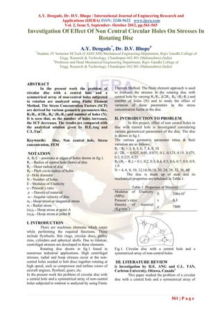
  • 1. A.Y. Deogade, Dr. D.V. Bhope / International Journal of Engineering Research and Applications (IJERA) ISSN: 2248-9622 www.ijera.com Vol. 2, Issue 5, September- October 2012, pp.561-565 Investigation Of Effect Of Non Central Circular Holes On Stresses In Rotating Disc A.Y. Deogade*, Dr. D.V. Bhope# * Student, IV Semester M.Tech (CAD/CAM) Mechanical Engineering Department, Rajiv Gandhi College of Engg. Research & Technology, Chandrapur-442 401 (Maharashtra) (India) # Professor and Head Mechanical Engineering Department, Rajiv Gandhi College of Engg. Research & Technology, Chandrapur-442 401 (Maharashtra) (India) ABSTRACT In the present work the problem of Element Method. The finite element approach is used circular disc with a central hole and a to evaluate the stresses in the rotating disc with symmetrical array of non-central holes subjected central hole by varying R2/R1, d/2R1, Rb/ (R2-R1) and to rotation are analyzed using Finite Element number of holes (N) and to study the effect of Method. The Stress Concentration Factors (SCF) variation of these parameters in the stress are derived for various geometric parameters like, concentration factor in the disc. R2/R1, d/2R1, Rb/ (R2-R1) and number of holes (N). It is seen that, as the number of holes increases, II. INTRODUCTION TO PROBLEM the SCF decreases. The results are compared with In this project, effect of non central holes in the analytical solution given by H.E.Ang and disc with central hole is investigated considering C.L.Tan1. various geometrical parameters of the disc. The disc is shown in fig.1. Keywords: Disc, Non central hole, Stress The various geometric parameter ratios & their concentration, FEM variation are as follows, R2 / R1 = 3, 4, 5, 6, 7, 8, 9, 10 NOTATION d / 2R1 = 0.025, 0.05, 0.075, 0.1, 0.125, 0.15, 0.175, A, B, C - positions at edges of holes shown in fig.1. 0.2, 0.225, 0.25 R1 - Radius of central hole (bore) of disc Rb/(R2 – R1) = 0.1, 0.2, 0.3, 0.4, 0.5, 0.6, 0.7, 0.8, 0.9, R2 - Outer radius of disc 1.0 Rb - Pitch circle radius of holes N = 4, 6, 8, 10, 12,14,16,18, 20, 24, 28, 32, 36, 40 d - Hole diameter The disc is made up of steel and its N - Number of holes mechanical properties are tabulated in Table.1. E - Modulus of Elasticity υ - Poisson’s ratio Table 1: Properties of Material ρ - Density of material Modulus of Elasticity E 200x103 ω - Angular velocity of disc (MPa) σθ - Hoop stress or tangential stress Poisson’s ratio ν 0.3 σr - Radial stress Density of material ρ 7800 (σθ)A - Hoop stress at point A (Kg/mm3) (σθ)B - Hoop stress at point B I. INTRODUCTION There are machines elements which rotate while performing the required functions. These include flywheels, thin rings, circular discs, pulley rims, cylinders and spherical shells. Due to rotation, centrifugal stresses are developed in these elements. Rotating disc shown in fig.1 found in Fig.1. Circular disc with a central hole and a numerous industrial applications. High centrifugal symmetrical array of non-central holes stresses, radial and hoop stresses occur at the non- central holes needed to bolt discs together rotating at III. LITERATURE REVIEW high speed, such as compressor and turbine rotors of i) Investigation by H.E. ANG and C.L. TAN, aircraft engines, flywheel, gears, etc. Carleton University, Ottawa, Canada1 In the present work the problem of circular disc with This paper studied the problem of a circular a central hole and a symmetrical array of non-central disc with a central hole and a symmetrical array of holes subjected to rotation is analyzed by using Finite 561 | P a g e
  • 2. A.Y. Deogade, Dr. D.V. Bhope / International Journal of Engineering Research and Applications (IJERA) ISSN: 2248-9622 www.ijera.com Vol. 2, Issue 5, September- October 2012, pp.561-565 non-central holes subjected to rotation using the boundary integral equation method. Figure 2 shows the typical variations of KA with the The aim of this paper is to present and number of holes, N, for the different values of Rb, highlight some features of the results for the local considered: the variations for KB show identical stresses at the edge of the non-central holes in thin features. These trends were found to be true for all circular discs subjected to rotation. The computed the geometric cases and the loading conditions stresses at these two points (σθ )A and (σθ)B, are treated. presented. For generality, they are expressed in terms of stress factors KA, and KB, respectively. In The tabulated coefficients can be the case of disc rotation, they are defined as, conveniently interpolated to obtain intermediate KA = (σθ )A / σo values for the stress factors for discs which are within and KB = (σθ )B / σo the range of R2/R1, and Rb/(R2-R1) ratios and N Where, considered for the values of N less than 20 as shown 3+υ 1+3υ in Table 2 and Table 3. σo = 8 ρω2 R2 + 2R2 − 3+υ R2 1 2 1 …. (1) is the hoop stress at the bore of a plane Table 2: Coefficients of stress factor Equations, disc with the same bore and outer radii as the equation (3). For the case of disc rotation: d/2R1 = problem treated; the material density, 𝜌, Poisson's 0.05 ratio, and speed of rotation are also having the same values. For the results corresponding to the radial tension load case, KA=(σθ )A/σ …………(2a) And KB=(σθ)B/σ ……(2b) KA= α − βN ……… (3a) KB = ξ − ηN ; 20 ≤ N ≤ 40 ………(3b) The coefficients 𝛼, 𝛽, 𝜉, 𝜂 so obtained are listed in for all the cases treated. It should be remarked that the values of K A and KB calculated using equation and the tabulated coefficients, deviated, in general, by less than 0.5 percent from the corresponding BIE computed values. Table 3: Coefficients of stress factor Equations, In terms of the ligament efficiency of the perforated equation (3). For the case of disc rotation: d/2R1 = part of the disc, , which may be defined as, 0.075 a-d ∑= a …… (4) These values correspond to the following ranges of ∑ for the respective radius ratios of the disc: 0.3634-0.823 for R2/R1 = 2; 0.523-0.878 for R2/R1 = 3; and 0.618-0.906 for R2/R1 = 4. For each and every combination of the above set of geometric parameter values, the stress distributions in the disc were obtained for the load case of the disc rotating at speed ω and subjected to uniform radial tension 𝜎 at the outer periphery. Poisson's ratio, υ was taken to be 0.3 throughout. ii) Investigation by H.FESSLER and T.E.THORPE, University of Nottingham, Nottingham This paper studied the frozen stress photo elastic technique to determine the hoop and radial stresses at the hole boundaries of sixty different hole configuration in flat discs. Rotating discs are frequently required in engineering, but special problems arise in gas turbine discs because these rotate at high speeds and must be as light as possible. Fig.2: Variation of KA with N; R2/R1=2, d/2R1=0.05 562 | P a g e
  • 3. A.Y. Deogade, Dr. D.V. Bhope / International Journal of Engineering Research and Applications (IJERA) ISSN: 2248-9622 www.ijera.com Vol. 2, Issue 5, September- October 2012, pp.561-565 iii) Investigation by CERLINCA Delia Aurora, 5.5 Rb/(R2-R1) 0.6 University of Suceava 4.5 0.7 The paper studied for an axially symmetrical 0.8 disk, with or without a central hole; there are 3.5 0.9 KA  analytical relations between stresses, strains, 1 depending on disk geometry and angular velocity. It 2.5 is known that the static condition a keyway induces 1.5 increased stresses acting as a stress concentrator. 0.5 iv) Investigation by H. FESSLER and T. E. 4 6 8 10 12 16 20 24 No. of holes  THORPE University of Nottingham, Nottingham This paper investigates the frozen-stress Fig.7: Variation of SCF with Respect to Number of photo elastic technique used to determine the stresses Holes for R2/R1=3 around reinforced non-central holes in discs. Both 4 Rb/(R2-R1) circular bosses and a thickened annulus were used as 0.4 3.5 reinforcements. Calculations by Green, Hooper, and 0.5 Hetherington were found to predict the mean stresses 3 0.6 (through the thickness) well but these calculations 2.5 0.7 KA  cannot predict the peak stresses. The latter were not 2 0.8 significantly less than the values of the unreinforced 1.5 0.9 perforated discs. The stresses in a taper disc were 1 1 lower than in a disc of constant thickness. 0.5 4 6 8 10 12 16 20 24 28 32 36 No. of Holes  IV. VARIATION OF SCF WITH RESPECT TO GEOMETRICAL PARAMETERS Fig.8: Variation of SCF with Respect to Number of Holes for R2/R1=4 EVALUATED BY FE APPROACH Principal stress contours for some ratios R2/R1, Rb/ (R2-R1), d/2R1, N are shown in fig.3 to 3 Rb/(R2-R1) fig.6 as an illustration. 0.3 2.5 0.4 0.5 2 0.6 KA  0.7 1.5 0.8 1 0.9 1 0.5 Fig.3: Principal Stress Fig.4: Principal Stress 4 6 8 10 12 16 20 24 28 32 36 40 Contour (σθ) for R2/R1 Contour (σθ) for R2/R1=3, No. of holes  =3, Rb/(R2-R1)=0.8, Rb/(R2-R1)=0.9, d/2R1= Fig.9: Variation of SCF with Respect to Number of d/2R1=0.2,N=24 0.225 , N=4 Holes for R2/R1=5 2 Rb/(R2-R1) 0.3 1.5 0.4 0.5 KA  0.6 1 0.7 0.8 0.5 0.9 1 Fig.5: Principal Stress Fig.6: Principal Stress 0 Contour (σθ) for R2/R1= Contour (σθ) for R2/R1=4, 4 6 8 10 12 16 20 24 28 32 36 40 No. of holes  4, Rb/(R2-R1)= 0.8, Rb/(R2-R1)=1,d/2R1=0.25, Fig.10: Variation of SCF with Respect to Number of d/2R1=0.2, N=4 N=36 Holes for R2/R1=6 An effort is made to show the variation of SCF with respect to geometrical parameter of disc i, e, Rb/(R2-R1), R2/R1, d/2R1 and number of holes (N). These variations are shown in Fig.7 to Fig. 14. 563 | P a g e
  • 4. A.Y. Deogade, Dr. D.V. Bhope / International Journal of Engineering Research and Applications (IJERA) ISSN: 2248-9622 www.ijera.com Vol. 2, Issue 5, September- October 2012, pp.561-565 3 Rb/(R2-R1) Table 4: Comparison of FE and Analytical Results for 0.2 2.5 0.3 d/2R1=0.05 0.4 R / (R2 σθ|FEM at 2 R2/ b d/ σθ|THEO. KA| KA  0.5 (R2- Rb d N pt. A KA 0.6 R1 2R1 (MPa) The.$ 1.5 0.7 R1) (MPa) 1 0.8 20 485.858 260.032 1.868 1.243 0.9 24 498.441 260.032 1.916 1.220 0.5 1 28 471.526 260.032 1.813 1.197 4 6 8 10 12 16 20 24 28 32 36 40 0.6 24 0.05 2 No. of holes  32 476.938 260.032 1.834 1.174 Fig.11: Variation of SCF with Respect to Number of 36 460.247 260.032 1.769 1.151 Holes for R2/R1=7 40 460.83 260.032 1.772 1.128 20 464.486 260.032 1.786 1.163 2.5 Rb/(R2-R1) 24 436.965 260.032 1.680 1.143 0.2 0.3 28 471.523 260.032 1.813 1.124 2 3 0.7 28 0.05 2 0.4 32 414.451 260.032 1.593 1.104 0.5 36 397.778 260.032 1.529 1.084 1.5 0.6 KA  0.7 40 390.733 260.032 1.502 1.065 1 0.8 20 402.29 260.032 1.547 1.080 0.9 0.5 1 24 397.121 260.032 1.527 1.063 4 6 8 10 12 16 20 24 28 32 36 40 28 373.352 260.032 1.435 1.047 No. of holes  0.8 32 0.05 2 32 365.164 260.032 1.404 1.031 Fig12: Variation of SCF with Respect to 36 354.958 260.032 1.365 1.015 Number of Holes for R2/R1=8 40 343.583 260.032 1.321 0.998 2.5 Rb/(R2-R1) 0.2 20 721.946 457.622 1.577 1.192 2 0.3 24 699.263 457.622 1.528 1.176 0.5 30 0.05 2 0.4 28 706.564 457.622 1.543 1.160 KA --> 1.5 0.5 32 714.737 457.622 1.561 1.143 1 0.6 20 685.121 457.622 1.497 1.099 0.5 0.7 24 625.976 457.622 1.367 1.086 0.8 28 656.061 457.622 1.433 1.074 0 0.9 0.6 36 0.05 2 32 622.804 457.622 1.360 1.061 4 6 8 10 12 16 20 24 28 32 36 40 1 No. of Holes --> 36 602.582 457.622 1.316 1.049 Fig.13: Variation of SCF with Respect to 40 572.771 457.622 1.251 1.036 Number of Holes for R2/R1=9 20 608.248 457.622 1.329 1.017 4 24 599.54 457.622 1.310 1.007 2.5 Rb/(R2-R1) 28 560.41 457.622 1.224 0.997 0.2 0.7 42 0.05 2 2 32 541.045 457.622 1.182 0.9876 0.3 0.4 36 530.183 457.622 1.158 0.9778 1.5 0.5 40 528.798 457.622 1.155 0.968 0.6 20 552.879 457.622 1.208 0.9425 KA  1 0.7 24 547.907 457.622 1.197 0.9342 0.8 0.5 0.9 28 546.596 457.622 1.194 0.9260 0.8 48 0.05 2 4 6 8 10 12 16 20 24 28 32 36 40 1 32 537.205 457.622 1.173 0.9177 36 509.025 457.622 1.112 0.9095 40 490.968 457.622 1.072 0.9013 Fig.14: Variation of SCF with Respect to Number of Holes for R2/R1=10 V. COMPARISON OF FE RESULTS WITH ANALYTICAL RESULTS REPORTED BY H.E. ANG & C.L.TAN1 The physical geometries and SCF given by H.E.ANG and C.L.TAN1 and evaluated by FE approach are given in Table 3 and Table 4 for the ratio of d/2R1=0.05 and d/2R1=0.075 564 | P a g e
  • 5. A.Y. Deogade, Dr. D.V. Bhope / International Journal of Engineering Research and Applications (IJERA) ISSN: 2248-9622 www.ijera.com Vol. 2, Issue 5, September- October 2012, pp.561-565 Table 5: Comparison of FE and Analytical Results for The Stress Concentration Factors derived for various d/2R1=0.075 geometric parameters like, R2/R1, d/2R1, Rb/(R2-R1) and Rb/ (R2 σθ|FEM σθ| at number of holes (N) can serve as a guideline for designing R2/ d/ KA| (R2- Rb d N pt. A THEO. KA $ the perforated rotating disc. R1 2R1 The. R1)-R1) (MPa) (MPa) 20 485.858 260.032 1.868452 1.2477 REFERENCES 0.6 24 0.075 3 24 498.441 260.032 1.916842 1.2081 (1) H.E.Ang and C.L.Tan, ‘Stress Concentration at 20 464.486 260.032 1.786262 1.153 Holes in Thin Rotating Discs’, Journal of Strain Analysis 3 0.7 28 0.075 3 24 436.965 260.032 1.680425 1.1174 Vol.23, No.4, P. No. 223-225,1988 20 402.29 260.032 1.547076 1.0751 (2) FESSLER, H. and THORPE, T. E. ‘Optimization 0.8 32 0.075 3 of Stress Concentrations in Rotating Discs’, Journal of 24 397.121 260.032 1.527198 1.0448 20 721.946 457.622 1.577601 1.1658 Strain Analysis, Vol.2, P.No.152-358,1967 24 699.263 457.622 1.528034 1.1362 (3) FESSLER, H. and THORPE, T. E. ‘Reinforcement 0.5 30 0.075 3 of Non-central Holes in Rotating Discs’, Journal of Strain 28 706.564 457.622 1.543988 1.1066 32 714.737 457.622 1.561847 1.0771 Analysis, Vol.2, P.No.317-323, 1967 20 685.121 457.622 1.49713 1.0778 (4) H.E.Ang and C.L.Tan, ‘Stress Intensity Factors for Cracks at Holes in Thin Rotating Discs’, International 24 625.976 457.622 1.367886 1.0548 0.6 36 0.075 3 Journal of Fracture, 40, P.No.R3-R11, 1989. 28 656.061 457.622 1.433628 1.0318 (5) TAN, C. L. and FENNER, R. T. ‘Elastic Fracture 32 622.804 457.622 1.360955 1.0089 Mechanics by the Boundary Integral Equation Method’, 4 20 608.248 457.622 1.329147 1.0009 Proc. R. Soc. Lond., A369, P. No. 243-260, 1979 24 599.54 457.622 1.310118 0.9811 0.7 42 0.075 3 28 560.41 457.622 1.224611 0.9614 32 541.045 457.622 1.182295 0.9417 20 552.879 457.622 1.208154 0.9299 24 547.907 457.622 1.19729 0.9130 0.8 48 0.075 3 28 546.596 457.622 1.194425 0.8962 32 537.205 457.622 1.173903 0.8793 $ - Stress Concentration Factor reported by H.E. Ang and C.L. Tan. It is seen from the Table 4 & 5 that the SCF determined by FE approach and with analytical approach differ by 62 to 84%.This confirms that the analytical solution represented C.L.Tan and H.E.Ang may need some correction factors depend upon geometry of perforated disc. Hence, it can be suggested that the analytical approach may needs some refinement to predict the actual SCF in perforated disc. VI. DISCUSSION AND CONCLUSION 1. It is observed that as the number of holes increases the SCF decreases for most cases. But for some cases it is observed that the SCF increases abruptly after certain number of holes. This may be due to very less pitch width between the two consecutive holes. Thus there is a limit for the maximum number of holes to keep the working stresses within safe limits. 2. As it is also seen that as the pitch circle radius of non central holes increases, the SCF decreases. Thus the non central holes very close to the central hole should be avoided in practice. 3. As the diameter of non central holes increases the SCF decreases. This may be due to the smoothening of stress lines over larger curvature of hole. Thus larger diameter of non central hole is preferred in actual practice. 565 | P a g e