SlideShare a Scribd company logo
1 of 25
Download to read offline
Product: TRACK LOADER
Model: 955K TRACK LOADER 85J
Configuration: 955L TRAXCAVATOR 85J09510-UP (MACHINE) POWERED BY 3304 ENGINE
Disassembly and Assembly
955K TRACK-TYPE LOADER POWER TRAIN
Media Number -REG00861-00 Publication Date -01/11/1993 Date Updated -10/10/2001
Steering Clutches, Bevel Gear And Final Drive
SMCS - 1405-016
Steering Clutch Case Cover Removal
Viewed from front of machine 1-Right brake control rod. 2-Left brake control rod. 3-Right pedal return spring. 4-Left
pedal return spring. 5-Right steering clutch control rod. 6-Left steering clutch control rod. 7-Steering clutch case oil
supply line. 8-Tube. 9-Cover. 10-Oil filter. 11-Steering booster cover.
12. Remove steering booster.
13 Pins.
1/16
955L TRAXCAVATOR 85J09510-UP (MACHINE) POWERED BY 3304 ENGINE(...
2021/12/17
https://127.0.0.1/sisweb/sisweb/techdoc/techdoc_print_page.jsp?returnurl=/sis...
14-Bolts (eighteen). 15-Forged eyebolts (three). Install 3/8"-16 NC forged eyebolts and attach a hoist. 16-Steering
clutch case cover.
Steering Clutch And Bevel Gear Shaft Removal
1-Rod ends. When installing rod end and adjusting nut, adjust dimension between center of hole in rod end and outer
face of adjusting nut to dimension shown. Lock with lock nut. 2-Bolts (twenty). 3-Bearing caps. The caps are marked
L and R and should be installed on the correct side of the machine.
Steering Clutch Removal
1-Lock. 2-Nut. Loosen until there is .25 in. (6,4 mm) between nut and hub. 3-Steering clutch, bearing and yoke. Pull
2/16
955L TRAXCAVATOR 85J09510-UP (MACHINE) POWERED BY 3304 ENGINE(...
2021/12/17
https://127.0.0.1/sisweb/sisweb/techdoc/techdoc_print_page.jsp?returnurl=/sis...
the steering clutch from the shaft by using a 7F9540 Hydraulic Puller, 6F25 or 3S6224 Pump Group, 8B7548 Push
Puller, two 8B7556 Adapters and an 8B7561 Step Plate.
Steering Clutch Installation
Be certain the splines on the bevel gear shaft and in the steering clutch driving drum are clean, dry
and free from burrs.
1. With the splines meshing, push the clutch onto the shaft as far as possible by hand.
2. Using a 7M7236 Adapter Group, 7F9540 Hydraulic Puller and 6F25 or 3S6224 Pump Group,
press the steering clutch driving drum onto the bevel gear shaft with a pressure of 15-20 tons (13,6
-18,1 M. tons). The distance between the face of the drum and the shoulder of the shaft must then
be .12±.03 in. (3,0±0,8 mm).
3. Install the steering clutch retaining nut. Tighten to a torque of 250±50 lb. ft. (34,6±6,9 mkg).
Install the lock.
Steering Clutch Disassembly
To remove or install locks (1) use a 7F9540 Hydraulic Puller, 6F25 or 3S6224 Pump Group, 8B7548 Push Puller, two
8B7556 Adapters, 8B7561 Step Plate and 7S8431 Spring Compressor Plate.
3/16
955L TRAXCAVATOR 85J09510-UP (MACHINE) POWERED BY 3304 ENGINE(...
2021/12/17
https://127.0.0.1/sisweb/sisweb/techdoc/techdoc_print_page.jsp?returnurl=/sis...
NOTE: If new discs (8) are installed, no precaution is necessary as to which face is up. If the
same discs are installed, they must be replaced with the same face up. Place the top discs on the
bottom of the stack.
Steering Clutch Release Bearing Removal And Installation
1-Setscrews (two). 2-Nut. 3-Retaining ring. 4-Thrust bearing. 5-Bearing cage and yoke. 6-Steering clutch (shown with
drum installed to protect and align teeth of discs).
NOTE: The bearing (4) is a thrust bearing and must be installed with the widest side of the inner
race next to the nut.
1. Assemble the parts in the reverse order of disassembly.
2. After the nut has been secured, drill two diametrically opposed 13/64 in. holes, .38 in. (9,6 mm)
deep on the parting line of the plate assembly and the nut.
3. Using a 1/4"-20 NC tap, tap each hole .25 in. (6,3 mm) deep.
4. Install the two hollow head setscrews.
5. Peen over the nut and plate assembly around the setscrews to retain them.
Bevel Gear Shaft Bearings And Bevel Gear Removal
1-Cage, nut and cup. 2-Bearing. The bevel gear shaft bearings can be removed by using an 8B7548 Push Puller,
8B7549 Legs, 8B7551 Bearing Puller Attachment, 7F9540 Hydraulic Puller and a 6F25 or 3S6224 Pump Group. 3-
Nuts (eight). 4-Bolts (eight). 5-Bevel gear.
NOTE: Heat the bearings in oil before installing on shaft. The inner race must be seated against
the shoulder of the shaft.
4/16
955L TRAXCAVATOR 85J09510-UP (MACHINE) POWERED BY 3304 ENGINE(...
2021/12/17
https://127.0.0.1/sisweb/sisweb/techdoc/techdoc_print_page.jsp?returnurl=/sis...
Bevel Gear And Pinion Setting
The bevel gear and pinion must be located to obtain the correct tooth contact. The pinion can be
moved toward or away from the centerline of the bevel gear and bevel gear shaft with shims
located between the pinion shaft bearing cage and the bevel gear case. Adjusting nuts, on each
bevel gear shaft bearing cage, permit moving the bevel gear toward or away from the centerline of
the bevel pinion shaft. Moving either the bevel gear or the pinion affects both backlash and tooth
contact so the two must be adjusted at the same time.
The relative positions of the bevel gear and the pinion gear will vary with different sets. The
correct amount of backlash is .008 ± .003 in. (0,2± 0,07 mm). When replacing an individual gear
or pinion, see the topic, BACKLASH ADJUSTMENT, for correct setting.
The pinion location can be obtained as described in the topic, BEVEL PINION LOCATION.
Preload the bevel gear shaft bearings as outlined in the covering topic before adjusting the
backlash or locating the bevel pinion.
Bevel Gear Shaft Bearing Preload
Typical example of bevel gear shaft bearing preload. Illustrated are : 1-7M7239 Wrench. 2-Nut. 3-Nut.
Use a 7M7239 Wrench to tighten the nuts.
Make certain the bevel gear and bevel pinion gear do not bind.
Use a pry bar to make certain there is no bevel gear shaft bearing end clearance.
Backlash Adjustment
The amount of backlash between each bevel gear and pinion set on original installation, is
determined at the factory and marked on the outside diameter of the bevel gear. On a replacement
gear or pinion, adjust the backlash to .008±.003 in. (0,2±0,07 mm).
1. Secure a dial indicator to the bevel gear case as shown.
2. Lock the bevel gear so it cannot rotate.
3. Place the finger of the dial indicator on the pinion gear tooth.
4. Rock the pinion gear back and forth.
5/16
955L TRAXCAVATOR 85J09510-UP (MACHINE) POWERED BY 3304 ENGINE(...
2021/12/17
https://127.0.0.1/sisweb/sisweb/techdoc/techdoc_print_page.jsp?returnurl=/sis...
5. The amount of backlash is the difference in readings on the dial indicator.
6. Check the backlash at four different locations on the bevel gear, taking the lowest reading as the
position to check the backlash.
7. If the reading is too great, decrease the backlash by loosening the right adjusting nut and
tightening the left adjusting nut an equal amount.
Typical example of checking bevel gear backlash. Illustrated are: 1-Left adjusting nut. 2-Right adjusting nut.
8. To increase backlash, loosen the left adjusting nut and tighten the right adjusting nut an equal
amount.
NOTE: Bevel gear shaft bearing preload will be maintained only if the bearing slack caused by
loosening one adjusting nut is compensated for by tightening the other adjusting nut an equal
amount. See the topic, BEVEL GEAR SHAFT BEARING PRELOAD.
9. If the notches on the adjusting nuts and bearing cage caps are not aligned, turn the nuts to the
nearest notch and install the locks. After adjusting the bevel gear, tighten the bolts holding the
bearing caps and lock them in place. Tighten and lock the bolts that secure the bevel pinion gear
bearing cage to the bevel gear case.
Bevel Pinion Location
If the same pinion shaft is reinstalled in the same bevel gear case, use the same shims between the
pinion shaft bearing cage and the bevel gear case that were removed. The pinion can be located by
observing the tooth contact pattern made by the pinion gear teeth on the bevel gear teeth. This can
be done in the following manner.
Use sufficient shims between the pinion shaft bearing cage and the bevel gear case to align the
heel ends of the bevel gear and pinion gear teeth. This will place the pinion in nearly the correct
relationship with the bevel gear.
6/16
955L TRAXCAVATOR 85J09510-UP (MACHINE) POWERED BY 3304 ENGINE(...
2021/12/17
https://127.0.0.1/sisweb/sisweb/techdoc/techdoc_print_page.jsp?returnurl=/sis...
This illustrates aligning the bevel gear and pinion.
Adding shims will move the pinion gear away from the centerline of the bevel gear shaft.
Removing shims will move the pinion toward the centerline of the bevel gear shaft.
Adjust the bevel gear backlash as described in the topic, BACKLASH ADJUSTMENT. This
should give a very close adjustment.
To further check the adjustment, brush Prussian blue or red lead sparingly on the bevel gear teeth.
When the pinion is rotated, the red lead is squeezed away by the contact of the teeth, leaving bare
areas of the contacts. Sharper impressions can be obtained by applying a small amount of
resistance to the bevel gear while rotating the pinion. When making adjustments, check the convex
side of the bevel gear teeth. The reverse or concave side contact should automatically be correct
when the convex side is correct.
FIG. A - This illustrates proper tooth contact pattern.
With adjustments properly made, the correct tooth contact in Fig. A will be obtained. The area of
contact starts near the toe of the gear and extends about 30 per cent of the tooth length. This
contact pattern is obtained with no load applied to the gears. This adjustment results in a quiet
running bevel gear and pinion set which, because when the load is applied it is distributed over the
teeth within the proper area, will give maximum service life. It is permissible for the tooth contact
area to be slightly greater on the concave face.
7/16
955L TRAXCAVATOR 85J09510-UP (MACHINE) POWERED BY 3304 ENGINE(...
2021/12/17
https://127.0.0.1/sisweb/sisweb/techdoc/techdoc_print_page.jsp?returnurl=/sis...
FIG. B - This illustrates short toe contact.
In Fig. B, the pinion is too far away from the centerline of the bevel gear shaft. This causes the
teeth to bear on the toe ends of the convex faces and toward the heel end of the concave faces. To
correct this, move the pinion toward the gear by removing shims from the bevel pinion bearing
cage. Recheck the backlash, changing it if necessary, and again check the tooth contact pattern. To
correct the backlash, move the bevel gear away from the pinion.
FIG. C - This illustrates short heel contact.
In Fig. C, the pinion is too close to the centerline of the bevel gear shaft. This causes the teeth to
bear on the toe ends of the concave faces and the heel ends of the convex faces. To correct, add
shims to the bevel pinion bearing cage. Then, recheck the backlash and tooth contact patterns. To
correct the backlash, move the bevel gear toward the pinion.
Several adjustments of both the pinion and bevel gear may be necessary before correct tooth
contact and backlash are obtained.
Always remember that the backlash will also affect the tooth contact pattern. Therefore, be sure
the backlash is properly adjusted before checking the adjustment of the pinion.
Brake Band And Drum Removal And Installation
1-Brake drum. 2-Brake band.
8/16
955L TRAXCAVATOR 85J09510-UP (MACHINE) POWERED BY 3304 ENGINE(...
2021/12/17
https://127.0.0.1/sisweb/sisweb/techdoc/techdoc_print_page.jsp?returnurl=/sis...
Final Drive Pinion Removal
1-Nut. 2-Lock. After removing lock, reinstall nut leaving about .25 in. (6,3 mm) between flange and nut. 3-Bolts (six).
4-3/8"-16 NC forged eyebolt and nut. Attach a hoist. Move the flange and pinion toward the centerline of the machine
until the cage clears the inside wall of the clutch case and the flange and pinion can be supported as shown. 5-Brake
drum flange. Remove from pinion by using an 8B7548 Push Puller, two 8B7556 Adapters, an 8B7560 Step Plate, a
7F9546 Hydraulic Puller and a 6F25 or 3S6224 Pump Group.
Final Drive Pinion Disassembly
1 Remove dowel by inserting a 1/4"-20 NC bolt into the dowel and pulling the dowel out of the
cage.
2 Remove the races with an 8B7548 Push Puller, 8B7551 Bearing Pulling Attachment and an
8B7560 Step Plate.
Final Drive Pinion Installation
Reassemble the final drive pinion and install it in the machine. Press the brake drum flange into
place with a force of 15-20 tons (13,6-18,1 M. tons) using a 7M7236 Adapter Group, 7F9540
Hydraulic Puller and a 6F25 or 3S6224 Pump Group.
9/16
955L TRAXCAVATOR 85J09510-UP (MACHINE) POWERED BY 3304 ENGINE(...
2021/12/17
https://127.0.0.1/sisweb/sisweb/techdoc/techdoc_print_page.jsp?returnurl=/sis...
The distance between the face of the flange and the shoulder of the pinion should be .12±.03 in.
(3,0±0,7 mm).
Final Drive Removal And Installation (As A Unit)
1-Cap.
2-Lock. 3-Nut. 4-Washer. 5-Bearing.
10/16
955L TRAXCAVATOR 85J09510-UP (MACHINE) POWERED BY 3304 ENGIN...
2021/12/17
https://127.0.0.1/sisweb/sisweb/techdoc/techdoc_print_page.jsp?returnurl=/sis...
6-Shims. For alignment of track roller frame and sprocket. See ALIGNMENT OF TRACK ROLLER FRAMES. 7-
Holder, and bearing cage. 8-Adjusting nut.
NOTE: Replace the nut (3) on the end of the sprocket shaft leaving some space between it and the
end of the bearing cage holder. The holder assembly (7) can be removed by turning the nut (8) in a
clockwise direction with a 7F9306 Spanner Wrench.
9-Duo-Cone floating seals (two). Remove the Duo-Cone floating seals for their protection. Use 9M5143 Seal Installer
to remove or install Duo-Cone seals. One is in the retainer on the sprocket. The other is in a retainer in the adjusting
nut. See the GENERAL INSTRUCTIONS for seal removal and installation. 10-Bolts (twenty-four).
11. Attach a hoist to the sprocket. Use two 3/8" -16 NC forcing screws to separate the final drive
case from the steering clutch case.
Final Drive Removal And Disassembly
11/16
955L TRAXCAVATOR 85J09510-UP (MACHINE) POWERED BY 3304 ENGIN...
2021/12/17
https://127.0.0.1/sisweb/sisweb/techdoc/techdoc_print_page.jsp?returnurl=/sis...
Sprocket Segment Removal And Installation
1. Remove sprocket guards.
2. Remove bolts and nuts (2) and remove sprocket segment (1).
12/16
955L TRAXCAVATOR 85J09510-UP (MACHINE) POWERED BY 3304 ENGIN...
2021/12/17
https://127.0.0.1/sisweb/sisweb/techdoc/techdoc_print_page.jsp?returnurl=/sis...
3. At installation place machined side of segment (1) towards hub and head of retaining bolt
against inside of hub.
4. Lubricate threads of bolts with high pressure lubricant or 9M3710 Anti-Seize Compound and
tighten all nuts to 130 ± 30 lb. ft. (19,0 ± 4,1 mkg), then tighten each nut an additional 1/3 turn.
See Tool Selection Chart for tools to remove solid sprocket hubs on later machines.
1, 3, 6 Remove dowels by inserting 1/4"-20 NC bolt into the dowels and pulling them out of the
housing.
2 Use two 3/8"-16 NC forcing screws to separate final drive case from steering clutch case.
4 Remove bearings with an 8B7554 Puller and an 8B7552 Forcing Bolt.
5 Remove inner races by heating evenly with a torch so they will expand.
7 Remove cone using an 8H705 Puller.
8 Remove cup by arc welding a bead around its inside diameter causing it to shrink. Install new
cup by chilling and driving into bore.
NOTICE
Make certain the ground lead is connected to the bevel gear case to
prevent arcing through bearings.
9 Remove the sprocket shaft by removing the retainer nut under the steering clutch case and by
using a 6F25 or 3S6224 Pump Group, 7F9831 Cylinder Group, 5F9888 Coupling Adapter,
5F9879 Adapter, 5F9892 Pin and a 5F9890 Sprocket Shaft Puller Group.
10 Remove cone by forcing it off the hub with the sprocket retaining nut. Use a 5F9693 Wrench,
to turn the nut. Heat the cone to install on hub.
11 Use nut to force off cone then reinstall nut so there is about .25 in. (6,3 mm) between it and the
sprocket.
Be sure that the nut is installed as stated in item 11 to prevent the
sprocket from jumping off the hub after it has broken loose from the
press fit.
12 Remove sprocket using a 6F25 or 3S6224 Pump Group, 7F9831 Cylinder Group, 5F7694 Plug,
three 5F9040 Arm Groups and two 7S9484 Spacer assemblies.
13/16
955L TRAXCAVATOR 85J09510-UP (MACHINE) POWERED BY 3304 ENGIN...
2021/12/17
https://127.0.0.1/sisweb/sisweb/techdoc/techdoc_print_page.jsp?returnurl=/sis...
13 Shims used to align track roller frame with sprocket. See TRACK ROLLER FRAME
ADJUSTMENT.
14
Replace sprocket shaft nut on the sprocket shaft with some space
between it and the holder assembly (14). This prevents the holder
assembly from jumping off the shaft after it has broken loose from the
taper fit.
Turn the final drive adjusting nut clockwise with a 7F9306 Spanner Wrench to remove the bearing
cage holder assembly.
15 Use a 9M5143 Seal Installer to remove or install Duo-Cone seals.
Final Drive Assembly
Sprocket Shaft Installation
Using a 5F9889 Plug, 5F9885 Adapter (threaded against the shoulder on the sprocket shaft), and a
5F9892 Pin, drive the sprocket shaft into the bevel gear case (with the key slot facing upward)
until the distance between the face of the outer bearing cage holder (hand held in place on the
taper of the sprocket shaft) and the parting line between the final drive case and the bevel gear
case is 10.34±.062 in. (262,64±1,57 mm).
14/16
955L TRAXCAVATOR 85J09510-UP (MACHINE) POWERED BY 3304 ENGIN...
2021/12/17
https://127.0.0.1/sisweb/sisweb/techdoc/techdoc_print_page.jsp?returnurl=/sis...
Install the sprocket shaft retainer nut and tighten securely. To lock in place, drill a 5/16" hole
through one of the notches in the nut through the nut and into the shaft to a total depth of 1.14 in.
(30,2 mm).
This drawing shows locking of the sprocket shaft retaining nut. C-5/16" drill, 1.14 in. (30,2 mm) deep.
Place the pin in the hole and install the snap ring to hold the pin in place.
Sprocket Installation
To install the sprocket use a 5F9879 Adapter, 5F9888 Coupling Adapter, 7F5288 Pusher Group,
7F9831 Cylinder Group, 5F9892 Coupling Pin and a 6F25 or 3S6224 Pump Group. Press the
sprocket onto the hub with a pressure of 35-40 tons (31,7-36,3 M. tons). The distance between the
face of the sprocket hub and the shoulder of spline should be .12±.06 in. (3,0±1,5 mm).
15/16
955L TRAXCAVATOR 85J09510-UP (MACHINE) POWERED BY 3304 ENGIN...
2021/12/17
https://127.0.0.1/sisweb/sisweb/techdoc/techdoc_print_page.jsp?returnurl=/sis...
Final Drive Bearing Preload Adjustment
Preload the final drive bearings by turning the adjusting nut counterclockwise with a 7F9306
Spanner Wrench. Apply a torque of 1050±150 lb. ft. (145,2±20,7 mkg).
For an illustrated step-by-step procedure, see the MAINTENANCE GUIDE.
16/16
955L TRAXCAVATOR 85J09510-UP (MACHINE) POWERED BY 3304 ENGIN...
2021/12/17
https://127.0.0.1/sisweb/sisweb/techdoc/techdoc_print_page.jsp?returnurl=/sis...
Product: TRACK LOADER
Model: 955K TRACK LOADER 85J
Configuration: 955L TRAXCAVATOR 85J09510-UP (MACHINE) POWERED BY 3304 ENGINE
Disassembly and Assembly
955K TRACK-TYPE LOADER POWER TRAIN
Media Number -REG00861-00 Publication Date -01/11/1993 Date Updated -10/10/2001
Undercarriage
SMCS - 1405-016
Relieving Track Tension
Be certain the hydraulic pressure in the track adjusting mechanism is
completely relieved and the cylinder can be moved to the rear into the
recoil spring front pilot before attempting to separate the track or
remove the track adjusting mechanism.
Release the pressure in the hydraulic track adjuster cylinder, WITH CAUTION as given in the
following steps:
This is a view of the hydraulic track adjuster. Items indicated are: 1-Relief valve. 2-Fill valve. 3-Vent holes. 4-Cylinder.
5-Recoil spring front pilot.
Because of the hydraulic pressure in the track adjuster cylinder, never
visually inspect the vent holes and valves to see if lubricant is escaping.
1/14
955L TRAXCAVATOR 85J09510-UP (MACHINE) POWERED BY 3304 ENGINE(...
2021/12/17
https://127.0.0.1/sisweb/sisweb/techdoc/techdoc_print_page.jsp?returnurl=/sis...
Always observe the cylinder to see that it moves to the rear into the
recoil spring front pilot.
1. Turn relief valve counterclockwise one turn to allow lubricant to escape from vent hole just below
RELIEF valve. Wait momentarily. If the cylinder does not retract turn FILL valve counterclockwise
one turn.
2. If the cylinder does not retract into the front pilot, loosen the RELIEF valve until it contacts the
underside of the guard. Lubricant should escape through slot in the lower section of threads.
3. If the cylinder does not retract loosen FILL valve until it contacts the underside of the guard.
Lubricant should then escape through slot in the lower section of threads.
4. If the cylinder does not retract into the front pilot, the machine should be started and moved
forward and backward.
5. If moving the machine does not cause the cylinder to retract, insert a draw bar pin between the
track and sprocket. Move the machine backward so the track will be forced upward by the pin. This
will apply additional tension to the track.
This is a drawing of the track adjuster mechanism. The items indicated are: 1-Relief valve. 2-Fill valve. 3-Vent holes. 6-
Slots. A-Unthreaded section, relief valve. B-Unthreaded section, fill valve.
Separating Track
1. Relief track tension.
2. Remove the master pin using the 2S8210 Track Tool Group.
3. Separate the track.
2/14
955L TRAXCAVATOR 85J09510-UP (MACHINE) POWERED BY 3304 ENGINE(...
2021/12/17
https://127.0.0.1/sisweb/sisweb/techdoc/techdoc_print_page.jsp?returnurl=/sis...
4-Spacers (two). 5-Coned disc seal washers (four). 6-Master links (two).
7. Back the machine slowly, allowing the track to ride over the carrier roller and off the sprocket.
Track Disassembly
1 At assembly tighten track shoe bolts to a torque of 130 ± 30 lb. ft. (18 ± 4,1 mkg) plus an
additional 1/3 turn. Install nuts with rounded corners next to the track link.
3 Remove and install pins with 2S8210 Track Tool Group.
4 Remove and install bushings with 2S8210 Track Tool Group. When installing the master bushing
the ends should be flush with the outside faces of the links. Other bushings should protrude past the
outside face of the links .321 ± .005 in. (8,15 ± 0,13 mm).
Installing Track
1. Back the machine until the sprocket is just ahead of the master links of the track.
2. Insert a bar into the links and help the track climb over the sprocket. Drive the machine forward
slowly.
3/14
955L TRAXCAVATOR 85J09510-UP (MACHINE) POWERED BY 3304 ENGINE(...
2021/12/17
https://127.0.0.1/sisweb/sisweb/techdoc/techdoc_print_page.jsp?returnurl=/sis...
Always hold the bar as illustrated.
3. Continue to carry the track over the rollers and front idler. Carry track high enough to clear carrier
rollers.
4. Place a block under the first shoe, drive forward until master links and track links are about 1 in.
(25,4 mm) apart. Install the coned disc seal washers and spacer in each master link.
This drawing shows the installation of coned disc seal washers and spacers. The parts pointed out are: 1-Spacers (two). 2
and 3-Coned disc seal washers (four). 4-Master links (two). 5-Track links (two).
5. Install each set of coned disc seal washers (as shown) with the inside diameters in contact. Install
spacers (as shown) with beveled edges toward one another.
4/14
955L TRAXCAVATOR 85J09510-UP (MACHINE) POWERED BY 3304 ENGINE(...
2021/12/17
https://127.0.0.1/sisweb/sisweb/techdoc/techdoc_print_page.jsp?returnurl=/sis...
6. Assemble FT573 Holding Tool (Fabricated Tool) onto master links and tighten each bolt to
compress seal washers. The spacers will be flush with inner face of links when seal washers are
properly compressed.
7. Move the machine forward and drive the track together until the spacers are held in place by track
links.
8. Remove the holding tool. Align the holes and install the master pin.
9. Adjust the track tension. See MAINTENANCE GUIDE.
Track Roller Frame Removal And Installation
1-Bolts (four). 2-Bolts. At installation lubricate threads with a thick mixture of oil and flowers of sulphur or an
equivalent lubricant.
3-Bolts (nine). At installation lubricate threads with a thick mixture of oil and flowers of sulphur or an equivalent
lubricant. 4-Shims. For parallel alignment of track roller frames. 5-Bolts (six). At installation lubricate threads with a
thick mixture of oil and flowers of sulphur or equivalent lubricant.
6. Raise the side of the machine about 6 in. (152,4 mm); block securely. Remove the track roller
frame by rolling it forward along the track.
5/14
955L TRAXCAVATOR 85J09510-UP (MACHINE) POWERED BY 3304 ENGINE(...
2021/12/17
https://127.0.0.1/sisweb/sisweb/techdoc/techdoc_print_page.jsp?returnurl=/sis...
7-Track roller frame replaceable wear strips.
Alignment Of Track Roller Frames
Aligning Track Roller Frame with Sprocket
The items involved in aligning the sprocket and track roller frame are: 1-Rear track roller. 2-Drive sprocket. A-
Clearance. B-Clearance.
1. Center the recess of the rear track roller so the clearances between the sprocket and either edge of
the track roller rim are equal.
2. Add shims (see FINAL DRIVE DISASSEMBLY) between the washer assembly and the holder
assembly to move the roller frame out, decreasing the clearance (A). Remove shims between the
washer assembly and the holder assembly to allow the roller frame to move in, decreasing clearance
(B).
Parallel Alignment of Track Roller Frames
1. Align the track roller frames with the sprockets.
2. Measure the distance between the insides of the track roller frame channels at the rear.
6/14
955L TRAXCAVATOR 85J09510-UP (MACHINE) POWERED BY 3304 ENGINE(...
2021/12/17
https://127.0.0.1/sisweb/sisweb/techdoc/techdoc_print_page.jsp?returnurl=/sis...
Suggest:
For more complete manuals. Please go to
the home page.
https://www.ebooklibonline.com
If the above button click is invalid. Please
download this document first, and then
click the above link to download the
complete manual.
Thank you so much for reading
The parts involved in parallel adjustment are: 1-Track roller frame. 2-Loader frame support. 3-Shims.
3. Measure the distance between the insides of the track roller frame channels just in front of the
loader frame support.
4. Install shims between each end of the loader frame support and the roller frames so the distance in
front is within .12 in. (3,05 mm) of the distance measured at the rear.
5. Install and tighten the bolts securing the loader frame support to the track roller frames and again
check the distances.
The items involved in parallel adjustment of the track roller frames are: 1-Track roller frame. 2-Loader frame support. 3-
Shims. A-Distance between roller frames at front. B-Distance between roller frames at rear.
Front Idler Removal And Installation
7/14
955L TRAXCAVATOR 85J09510-UP (MACHINE) POWERED BY 3304 ENGINE(...
2021/12/17
https://127.0.0.1/sisweb/sisweb/techdoc/techdoc_print_page.jsp?returnurl=/sis...
1-Bolts (four). Loosen until spring pressure is relieved.
3-Front idler. Attach hoist and remove by moving forward. 4-Plates (two). 5-Spring assemblies (four). 6-Plates (four).
Front Idler Disassembly
1 Apply 9M3710 Anti-Seize Compound in bearing bores and on bearing contact surfaces of shaft.
2 Tighten bolts to a torque of 40 lb. ft. (5,5 mkg). Seat tapered lockpins with a punch and hammer,
then retighten bolts to a torque of 50 ± 10 lb. ft. (6,9 ± 1,3 mkg).
3 Oil hole on plug end of shaft to be assembled up.
4 Coat the outside diameter of the bushing assemblies with white lead. Use FT578 Alignment Tool
Group (Fabricated Tool) to insure alignment of bolt holes.
5 Use 5M2196 Seal Installer to remove and install Duo-Cone seals.
6, 8 Use shims to align the front idler with the track. If the idler is too far toward the outside, move
shims from the bearing at the inner end of the idler hub to the outer bearing. If the idler is too far
toward the inside, reverse the process. After alignment, .06 in. (1,52 mm) should be maintained
between each plate and track roller frame by using shims.
8/14
955L TRAXCAVATOR 85J09510-UP (MACHINE) POWERED BY 3304 ENGINE(...
2021/12/17
https://127.0.0.1/sisweb/sisweb/techdoc/techdoc_print_page.jsp?returnurl=/sis...

More Related Content

More from gua6982552kun

Massey Ferguson MF 384 S TRACTOR (- 300993) Parts Catalogue Manual Instant Do...
Massey Ferguson MF 384 S TRACTOR (- 300993) Parts Catalogue Manual Instant Do...Massey Ferguson MF 384 S TRACTOR (- 300993) Parts Catalogue Manual Instant Do...
Massey Ferguson MF 384 S TRACTOR (- 300993) Parts Catalogue Manual Instant Do...gua6982552kun
 
Massey Ferguson MF 384 F TRACTOR, - 0894 Parts Catalogue Manual Instant Downl...
Massey Ferguson MF 384 F TRACTOR, - 0894 Parts Catalogue Manual Instant Downl...Massey Ferguson MF 384 F TRACTOR, - 0894 Parts Catalogue Manual Instant Downl...
Massey Ferguson MF 384 F TRACTOR, - 0894 Parts Catalogue Manual Instant Downl...gua6982552kun
 
Caterpillar Cat TH460B Telehandler (Prefix SLF) Service Repair Manual Instant...
Caterpillar Cat TH460B Telehandler (Prefix SLF) Service Repair Manual Instant...Caterpillar Cat TH460B Telehandler (Prefix SLF) Service Repair Manual Instant...
Caterpillar Cat TH460B Telehandler (Prefix SLF) Service Repair Manual Instant...gua6982552kun
 
Caterpillar Cat TH350B Telehandler (Prefix SLD) Service Repair Manual Instant...
Caterpillar Cat TH350B Telehandler (Prefix SLD) Service Repair Manual Instant...Caterpillar Cat TH350B Telehandler (Prefix SLD) Service Repair Manual Instant...
Caterpillar Cat TH350B Telehandler (Prefix SLD) Service Repair Manual Instant...gua6982552kun
 
Caterpillar Cat TH340B Telehandler (Prefix SLC) Service Repair Manual Instant...
Caterpillar Cat TH340B Telehandler (Prefix SLC) Service Repair Manual Instant...Caterpillar Cat TH340B Telehandler (Prefix SLC) Service Repair Manual Instant...
Caterpillar Cat TH340B Telehandler (Prefix SLC) Service Repair Manual Instant...gua6982552kun
 
Caterpillar Cat TH215 Telehandler (Prefix CEG) Service Repair Manual Instant ...
Caterpillar Cat TH215 Telehandler (Prefix CEG) Service Repair Manual Instant ...Caterpillar Cat TH215 Telehandler (Prefix CEG) Service Repair Manual Instant ...
Caterpillar Cat TH215 Telehandler (Prefix CEG) Service Repair Manual Instant ...gua6982552kun
 
Caterpillar Cat TH210 Telehandler (Prefix CEC) Service Repair Manual Instant ...
Caterpillar Cat TH210 Telehandler (Prefix CEC) Service Repair Manual Instant ...Caterpillar Cat TH210 Telehandler (Prefix CEC) Service Repair Manual Instant ...
Caterpillar Cat TH210 Telehandler (Prefix CEC) Service Repair Manual Instant ...gua6982552kun
 
Caterpillar Cat TH103 Telehandler (Prefix 3PN) Service Repair Manual Instant ...
Caterpillar Cat TH103 Telehandler (Prefix 3PN) Service Repair Manual Instant ...Caterpillar Cat TH103 Telehandler (Prefix 3PN) Service Repair Manual Instant ...
Caterpillar Cat TH103 Telehandler (Prefix 3PN) Service Repair Manual Instant ...gua6982552kun
 
Caterpillar Cat TH83 Telehandler (Prefix 3RN) Service Repair Manual Instant D...
Caterpillar Cat TH83 Telehandler (Prefix 3RN) Service Repair Manual Instant D...Caterpillar Cat TH83 Telehandler (Prefix 3RN) Service Repair Manual Instant D...
Caterpillar Cat TH83 Telehandler (Prefix 3RN) Service Repair Manual Instant D...gua6982552kun
 
Caterpillar Cat D6R STD TRACK-TYPE TRACTOR (Prefix EMM) Service Repair Manual...
Caterpillar Cat D6R STD TRACK-TYPE TRACTOR (Prefix EMM) Service Repair Manual...Caterpillar Cat D6R STD TRACK-TYPE TRACTOR (Prefix EMM) Service Repair Manual...
Caterpillar Cat D6R STD TRACK-TYPE TRACTOR (Prefix EMM) Service Repair Manual...gua6982552kun
 
Caterpillar Cat D6G2 XL TRACK-TYPE TRACTOR (Prefix P6G) Service Repair Manual...
Caterpillar Cat D6G2 XL TRACK-TYPE TRACTOR (Prefix P6G) Service Repair Manual...Caterpillar Cat D6G2 XL TRACK-TYPE TRACTOR (Prefix P6G) Service Repair Manual...
Caterpillar Cat D6G2 XL TRACK-TYPE TRACTOR (Prefix P6G) Service Repair Manual...gua6982552kun
 
Caterpillar Cat D5R2 TRACK-TYPE TRACTOR (Prefix WRE) Service Repair Manual In...
Caterpillar Cat D5R2 TRACK-TYPE TRACTOR (Prefix WRE) Service Repair Manual In...Caterpillar Cat D5R2 TRACK-TYPE TRACTOR (Prefix WRE) Service Repair Manual In...
Caterpillar Cat D5R2 TRACK-TYPE TRACTOR (Prefix WRE) Service Repair Manual In...gua6982552kun
 
Caterpillar Cat D5N TRACK-TYPE TRACTOR (Prefix AKD) Service Repair Manual Ins...
Caterpillar Cat D5N TRACK-TYPE TRACTOR (Prefix AKD) Service Repair Manual Ins...Caterpillar Cat D5N TRACK-TYPE TRACTOR (Prefix AKD) Service Repair Manual Ins...
Caterpillar Cat D5N TRACK-TYPE TRACTOR (Prefix AKD) Service Repair Manual Ins...gua6982552kun
 
Caterpillar Cat D5K XL TRACK-TYPE TRACTOR (Prefix WWW) Service Repair Manual ...
Caterpillar Cat D5K XL TRACK-TYPE TRACTOR (Prefix WWW) Service Repair Manual ...Caterpillar Cat D5K XL TRACK-TYPE TRACTOR (Prefix WWW) Service Repair Manual ...
Caterpillar Cat D5K XL TRACK-TYPE TRACTOR (Prefix WWW) Service Repair Manual ...gua6982552kun
 
Caterpillar Cat D4K2 XL TRACK-TYPE TRACTOR (Prefix MT3) Service Repair Manual...
Caterpillar Cat D4K2 XL TRACK-TYPE TRACTOR (Prefix MT3) Service Repair Manual...Caterpillar Cat D4K2 XL TRACK-TYPE TRACTOR (Prefix MT3) Service Repair Manual...
Caterpillar Cat D4K2 XL TRACK-TYPE TRACTOR (Prefix MT3) Service Repair Manual...gua6982552kun
 
Caterpillar Cat D4K2 XL TRACK-TYPE TRACTOR (Prefix KM2) Service Repair Manual...
Caterpillar Cat D4K2 XL TRACK-TYPE TRACTOR (Prefix KM2) Service Repair Manual...Caterpillar Cat D4K2 XL TRACK-TYPE TRACTOR (Prefix KM2) Service Repair Manual...
Caterpillar Cat D4K2 XL TRACK-TYPE TRACTOR (Prefix KM2) Service Repair Manual...gua6982552kun
 
Caterpillar Cat CB564D Vibratory Compactor (Prefix D4M) Service Repair Manual...
Caterpillar Cat CB564D Vibratory Compactor (Prefix D4M) Service Repair Manual...Caterpillar Cat CB564D Vibratory Compactor (Prefix D4M) Service Repair Manual...
Caterpillar Cat CB564D Vibratory Compactor (Prefix D4M) Service Repair Manual...gua6982552kun
 
Caterpillar Cat C15 Industrial Engine (Prefix N5F) Service Repair Manual Inst...
Caterpillar Cat C15 Industrial Engine (Prefix N5F) Service Repair Manual Inst...Caterpillar Cat C15 Industrial Engine (Prefix N5F) Service Repair Manual Inst...
Caterpillar Cat C15 Industrial Engine (Prefix N5F) Service Repair Manual Inst...gua6982552kun
 

More from gua6982552kun (20)

Massey Ferguson MF 384 S TRACTOR (- 300993) Parts Catalogue Manual Instant Do...
Massey Ferguson MF 384 S TRACTOR (- 300993) Parts Catalogue Manual Instant Do...Massey Ferguson MF 384 S TRACTOR (- 300993) Parts Catalogue Manual Instant Do...
Massey Ferguson MF 384 S TRACTOR (- 300993) Parts Catalogue Manual Instant Do...
 
Massey Ferguson MF 384 F TRACTOR, - 0894 Parts Catalogue Manual Instant Downl...
Massey Ferguson MF 384 F TRACTOR, - 0894 Parts Catalogue Manual Instant Downl...Massey Ferguson MF 384 F TRACTOR, - 0894 Parts Catalogue Manual Instant Downl...
Massey Ferguson MF 384 F TRACTOR, - 0894 Parts Catalogue Manual Instant Downl...
 
Caterpillar Cat TH460B Telehandler (Prefix SLF) Service Repair Manual Instant...
Caterpillar Cat TH460B Telehandler (Prefix SLF) Service Repair Manual Instant...Caterpillar Cat TH460B Telehandler (Prefix SLF) Service Repair Manual Instant...
Caterpillar Cat TH460B Telehandler (Prefix SLF) Service Repair Manual Instant...
 
Caterpillar Cat TH350B Telehandler (Prefix SLD) Service Repair Manual Instant...
Caterpillar Cat TH350B Telehandler (Prefix SLD) Service Repair Manual Instant...Caterpillar Cat TH350B Telehandler (Prefix SLD) Service Repair Manual Instant...
Caterpillar Cat TH350B Telehandler (Prefix SLD) Service Repair Manual Instant...
 
Caterpillar Cat TH340B Telehandler (Prefix SLC) Service Repair Manual Instant...
Caterpillar Cat TH340B Telehandler (Prefix SLC) Service Repair Manual Instant...Caterpillar Cat TH340B Telehandler (Prefix SLC) Service Repair Manual Instant...
Caterpillar Cat TH340B Telehandler (Prefix SLC) Service Repair Manual Instant...
 
Caterpillar Cat TH215 Telehandler (Prefix CEG) Service Repair Manual Instant ...
Caterpillar Cat TH215 Telehandler (Prefix CEG) Service Repair Manual Instant ...Caterpillar Cat TH215 Telehandler (Prefix CEG) Service Repair Manual Instant ...
Caterpillar Cat TH215 Telehandler (Prefix CEG) Service Repair Manual Instant ...
 
Caterpillar Cat TH210 Telehandler (Prefix CEC) Service Repair Manual Instant ...
Caterpillar Cat TH210 Telehandler (Prefix CEC) Service Repair Manual Instant ...Caterpillar Cat TH210 Telehandler (Prefix CEC) Service Repair Manual Instant ...
Caterpillar Cat TH210 Telehandler (Prefix CEC) Service Repair Manual Instant ...
 
Caterpillar Cat TH103 Telehandler (Prefix 3PN) Service Repair Manual Instant ...
Caterpillar Cat TH103 Telehandler (Prefix 3PN) Service Repair Manual Instant ...Caterpillar Cat TH103 Telehandler (Prefix 3PN) Service Repair Manual Instant ...
Caterpillar Cat TH103 Telehandler (Prefix 3PN) Service Repair Manual Instant ...
 
Caterpillar Cat TH103 Telehandler (Prefix 3PN) Service Repair Manual Instant ...
Caterpillar Cat TH103 Telehandler (Prefix 3PN) Service Repair Manual Instant ...Caterpillar Cat TH103 Telehandler (Prefix 3PN) Service Repair Manual Instant ...
Caterpillar Cat TH103 Telehandler (Prefix 3PN) Service Repair Manual Instant ...
 
Caterpillar Cat TH83 Telehandler (Prefix 3RN) Service Repair Manual Instant D...
Caterpillar Cat TH83 Telehandler (Prefix 3RN) Service Repair Manual Instant D...Caterpillar Cat TH83 Telehandler (Prefix 3RN) Service Repair Manual Instant D...
Caterpillar Cat TH83 Telehandler (Prefix 3RN) Service Repair Manual Instant D...
 
Caterpillar Cat TH83 Telehandler (Prefix 3RN) Service Repair Manual Instant D...
Caterpillar Cat TH83 Telehandler (Prefix 3RN) Service Repair Manual Instant D...Caterpillar Cat TH83 Telehandler (Prefix 3RN) Service Repair Manual Instant D...
Caterpillar Cat TH83 Telehandler (Prefix 3RN) Service Repair Manual Instant D...
 
Caterpillar Cat D6R STD TRACK-TYPE TRACTOR (Prefix EMM) Service Repair Manual...
Caterpillar Cat D6R STD TRACK-TYPE TRACTOR (Prefix EMM) Service Repair Manual...Caterpillar Cat D6R STD TRACK-TYPE TRACTOR (Prefix EMM) Service Repair Manual...
Caterpillar Cat D6R STD TRACK-TYPE TRACTOR (Prefix EMM) Service Repair Manual...
 
Caterpillar Cat D6G2 XL TRACK-TYPE TRACTOR (Prefix P6G) Service Repair Manual...
Caterpillar Cat D6G2 XL TRACK-TYPE TRACTOR (Prefix P6G) Service Repair Manual...Caterpillar Cat D6G2 XL TRACK-TYPE TRACTOR (Prefix P6G) Service Repair Manual...
Caterpillar Cat D6G2 XL TRACK-TYPE TRACTOR (Prefix P6G) Service Repair Manual...
 
Caterpillar Cat D5R2 TRACK-TYPE TRACTOR (Prefix WRE) Service Repair Manual In...
Caterpillar Cat D5R2 TRACK-TYPE TRACTOR (Prefix WRE) Service Repair Manual In...Caterpillar Cat D5R2 TRACK-TYPE TRACTOR (Prefix WRE) Service Repair Manual In...
Caterpillar Cat D5R2 TRACK-TYPE TRACTOR (Prefix WRE) Service Repair Manual In...
 
Caterpillar Cat D5N TRACK-TYPE TRACTOR (Prefix AKD) Service Repair Manual Ins...
Caterpillar Cat D5N TRACK-TYPE TRACTOR (Prefix AKD) Service Repair Manual Ins...Caterpillar Cat D5N TRACK-TYPE TRACTOR (Prefix AKD) Service Repair Manual Ins...
Caterpillar Cat D5N TRACK-TYPE TRACTOR (Prefix AKD) Service Repair Manual Ins...
 
Caterpillar Cat D5K XL TRACK-TYPE TRACTOR (Prefix WWW) Service Repair Manual ...
Caterpillar Cat D5K XL TRACK-TYPE TRACTOR (Prefix WWW) Service Repair Manual ...Caterpillar Cat D5K XL TRACK-TYPE TRACTOR (Prefix WWW) Service Repair Manual ...
Caterpillar Cat D5K XL TRACK-TYPE TRACTOR (Prefix WWW) Service Repair Manual ...
 
Caterpillar Cat D4K2 XL TRACK-TYPE TRACTOR (Prefix MT3) Service Repair Manual...
Caterpillar Cat D4K2 XL TRACK-TYPE TRACTOR (Prefix MT3) Service Repair Manual...Caterpillar Cat D4K2 XL TRACK-TYPE TRACTOR (Prefix MT3) Service Repair Manual...
Caterpillar Cat D4K2 XL TRACK-TYPE TRACTOR (Prefix MT3) Service Repair Manual...
 
Caterpillar Cat D4K2 XL TRACK-TYPE TRACTOR (Prefix KM2) Service Repair Manual...
Caterpillar Cat D4K2 XL TRACK-TYPE TRACTOR (Prefix KM2) Service Repair Manual...Caterpillar Cat D4K2 XL TRACK-TYPE TRACTOR (Prefix KM2) Service Repair Manual...
Caterpillar Cat D4K2 XL TRACK-TYPE TRACTOR (Prefix KM2) Service Repair Manual...
 
Caterpillar Cat CB564D Vibratory Compactor (Prefix D4M) Service Repair Manual...
Caterpillar Cat CB564D Vibratory Compactor (Prefix D4M) Service Repair Manual...Caterpillar Cat CB564D Vibratory Compactor (Prefix D4M) Service Repair Manual...
Caterpillar Cat CB564D Vibratory Compactor (Prefix D4M) Service Repair Manual...
 
Caterpillar Cat C15 Industrial Engine (Prefix N5F) Service Repair Manual Inst...
Caterpillar Cat C15 Industrial Engine (Prefix N5F) Service Repair Manual Inst...Caterpillar Cat C15 Industrial Engine (Prefix N5F) Service Repair Manual Inst...
Caterpillar Cat C15 Industrial Engine (Prefix N5F) Service Repair Manual Inst...
 

Recently uploaded

Not Sure About VW EGR Valve Health Look For These Symptoms
Not Sure About VW EGR Valve Health Look For These SymptomsNot Sure About VW EGR Valve Health Look For These Symptoms
Not Sure About VW EGR Valve Health Look For These SymptomsFifth Gear Automotive
 
call girls in Jama Masjid (DELHI) 🔝 >༒9953330565🔝 genuine Escort Service 🔝✔️✔️
call girls in Jama Masjid (DELHI) 🔝 >༒9953330565🔝 genuine Escort Service 🔝✔️✔️call girls in Jama Masjid (DELHI) 🔝 >༒9953330565🔝 genuine Escort Service 🔝✔️✔️
call girls in Jama Masjid (DELHI) 🔝 >༒9953330565🔝 genuine Escort Service 🔝✔️✔️9953056974 Low Rate Call Girls In Saket, Delhi NCR
 
UNIT-V-ELECTRIC AND HYBRID VEHICLES.pptx
UNIT-V-ELECTRIC AND HYBRID VEHICLES.pptxUNIT-V-ELECTRIC AND HYBRID VEHICLES.pptx
UNIT-V-ELECTRIC AND HYBRID VEHICLES.pptxDineshKumar4165
 
( Best ) Genuine Call Girls In Mandi House =DELHI-| 8377087607
( Best ) Genuine Call Girls In Mandi House =DELHI-| 8377087607( Best ) Genuine Call Girls In Mandi House =DELHI-| 8377087607
( Best ) Genuine Call Girls In Mandi House =DELHI-| 8377087607dollysharma2066
 
2024 TOP 10 most fuel-efficient vehicles according to the US agency
2024 TOP 10 most fuel-efficient vehicles according to the US agency2024 TOP 10 most fuel-efficient vehicles according to the US agency
2024 TOP 10 most fuel-efficient vehicles according to the US agencyHyundai Motor Group
 
BLUE VEHICLES the kids picture show 2024
BLUE VEHICLES the kids picture show 2024BLUE VEHICLES the kids picture show 2024
BLUE VEHICLES the kids picture show 2024AHOhOops1
 
原版1:1定制(IC大学毕业证)帝国理工学院大学毕业证国外文凭复刻成绩单#电子版制作#留信入库#多年经营绝对保证质量
原版1:1定制(IC大学毕业证)帝国理工学院大学毕业证国外文凭复刻成绩单#电子版制作#留信入库#多年经营绝对保证质量原版1:1定制(IC大学毕业证)帝国理工学院大学毕业证国外文凭复刻成绩单#电子版制作#留信入库#多年经营绝对保证质量
原版1:1定制(IC大学毕业证)帝国理工学院大学毕业证国外文凭复刻成绩单#电子版制作#留信入库#多年经营绝对保证质量208367051
 
Call Girl Service Global Village Dubai +971509430017 Independent Call Girls G...
Call Girl Service Global Village Dubai +971509430017 Independent Call Girls G...Call Girl Service Global Village Dubai +971509430017 Independent Call Girls G...
Call Girl Service Global Village Dubai +971509430017 Independent Call Girls G...kexey39068
 
VIP Kolkata Call Girl Kasba 👉 8250192130 Available With Room
VIP Kolkata Call Girl Kasba 👉 8250192130  Available With RoomVIP Kolkata Call Girl Kasba 👉 8250192130  Available With Room
VIP Kolkata Call Girl Kasba 👉 8250192130 Available With Roomdivyansh0kumar0
 
原版1:1复刻俄亥俄州立大学毕业证OSU毕业证留信学历认证
原版1:1复刻俄亥俄州立大学毕业证OSU毕业证留信学历认证原版1:1复刻俄亥俄州立大学毕业证OSU毕业证留信学历认证
原版1:1复刻俄亥俄州立大学毕业证OSU毕业证留信学历认证jdkhjh
 
UNIT-1-VEHICLE STRUCTURE AND ENGINES.ppt
UNIT-1-VEHICLE STRUCTURE AND ENGINES.pptUNIT-1-VEHICLE STRUCTURE AND ENGINES.ppt
UNIT-1-VEHICLE STRUCTURE AND ENGINES.pptDineshKumar4165
 
Dubai Call Girls Services Call 09900000000
Dubai Call Girls Services Call 09900000000Dubai Call Girls Services Call 09900000000
Dubai Call Girls Services Call 09900000000Komal Khan
 
办理克莱姆森大学毕业证成绩单|购买美国文凭证书
办理克莱姆森大学毕业证成绩单|购买美国文凭证书办理克莱姆森大学毕业证成绩单|购买美国文凭证书
办理克莱姆森大学毕业证成绩单|购买美国文凭证书zdzoqco
 
What Causes DPF Failure In VW Golf Cars & How Can They Be Prevented
What Causes DPF Failure In VW Golf Cars & How Can They Be PreventedWhat Causes DPF Failure In VW Golf Cars & How Can They Be Prevented
What Causes DPF Failure In VW Golf Cars & How Can They Be PreventedAutobahn Automotive Service
 
What Could Cause A VW Tiguan's Radiator Fan To Stop Working
What Could Cause A VW Tiguan's Radiator Fan To Stop WorkingWhat Could Cause A VW Tiguan's Radiator Fan To Stop Working
What Could Cause A VW Tiguan's Radiator Fan To Stop WorkingEscondido German Auto
 
UNIT-IV-STEERING, BRAKES AND SUSPENSION SYSTEMS.pptx
UNIT-IV-STEERING, BRAKES AND SUSPENSION SYSTEMS.pptxUNIT-IV-STEERING, BRAKES AND SUSPENSION SYSTEMS.pptx
UNIT-IV-STEERING, BRAKES AND SUSPENSION SYSTEMS.pptxDineshKumar4165
 
原版工艺美国普林斯顿大学毕业证Princeton毕业证成绩单修改留信学历认证
原版工艺美国普林斯顿大学毕业证Princeton毕业证成绩单修改留信学历认证原版工艺美国普林斯顿大学毕业证Princeton毕业证成绩单修改留信学历认证
原版工艺美国普林斯顿大学毕业证Princeton毕业证成绩单修改留信学历认证jjrehjwj11gg
 
办理萨省大学毕业证成绩单|购买加拿大USASK文凭证书
办理萨省大学毕业证成绩单|购买加拿大USASK文凭证书办理萨省大学毕业证成绩单|购买加拿大USASK文凭证书
办理萨省大学毕业证成绩单|购买加拿大USASK文凭证书zdzoqco
 
Call Girls Vastrapur 7397865700 Ridhima Hire Me Full Night
Call Girls Vastrapur 7397865700 Ridhima Hire Me Full NightCall Girls Vastrapur 7397865700 Ridhima Hire Me Full Night
Call Girls Vastrapur 7397865700 Ridhima Hire Me Full Nightssuser7cb4ff
 

Recently uploaded (20)

Not Sure About VW EGR Valve Health Look For These Symptoms
Not Sure About VW EGR Valve Health Look For These SymptomsNot Sure About VW EGR Valve Health Look For These Symptoms
Not Sure About VW EGR Valve Health Look For These Symptoms
 
call girls in Jama Masjid (DELHI) 🔝 >༒9953330565🔝 genuine Escort Service 🔝✔️✔️
call girls in Jama Masjid (DELHI) 🔝 >༒9953330565🔝 genuine Escort Service 🔝✔️✔️call girls in Jama Masjid (DELHI) 🔝 >༒9953330565🔝 genuine Escort Service 🔝✔️✔️
call girls in Jama Masjid (DELHI) 🔝 >༒9953330565🔝 genuine Escort Service 🔝✔️✔️
 
UNIT-V-ELECTRIC AND HYBRID VEHICLES.pptx
UNIT-V-ELECTRIC AND HYBRID VEHICLES.pptxUNIT-V-ELECTRIC AND HYBRID VEHICLES.pptx
UNIT-V-ELECTRIC AND HYBRID VEHICLES.pptx
 
( Best ) Genuine Call Girls In Mandi House =DELHI-| 8377087607
( Best ) Genuine Call Girls In Mandi House =DELHI-| 8377087607( Best ) Genuine Call Girls In Mandi House =DELHI-| 8377087607
( Best ) Genuine Call Girls In Mandi House =DELHI-| 8377087607
 
2024 TOP 10 most fuel-efficient vehicles according to the US agency
2024 TOP 10 most fuel-efficient vehicles according to the US agency2024 TOP 10 most fuel-efficient vehicles according to the US agency
2024 TOP 10 most fuel-efficient vehicles according to the US agency
 
BLUE VEHICLES the kids picture show 2024
BLUE VEHICLES the kids picture show 2024BLUE VEHICLES the kids picture show 2024
BLUE VEHICLES the kids picture show 2024
 
原版1:1定制(IC大学毕业证)帝国理工学院大学毕业证国外文凭复刻成绩单#电子版制作#留信入库#多年经营绝对保证质量
原版1:1定制(IC大学毕业证)帝国理工学院大学毕业证国外文凭复刻成绩单#电子版制作#留信入库#多年经营绝对保证质量原版1:1定制(IC大学毕业证)帝国理工学院大学毕业证国外文凭复刻成绩单#电子版制作#留信入库#多年经营绝对保证质量
原版1:1定制(IC大学毕业证)帝国理工学院大学毕业证国外文凭复刻成绩单#电子版制作#留信入库#多年经营绝对保证质量
 
Call Girl Service Global Village Dubai +971509430017 Independent Call Girls G...
Call Girl Service Global Village Dubai +971509430017 Independent Call Girls G...Call Girl Service Global Village Dubai +971509430017 Independent Call Girls G...
Call Girl Service Global Village Dubai +971509430017 Independent Call Girls G...
 
VIP Kolkata Call Girl Kasba 👉 8250192130 Available With Room
VIP Kolkata Call Girl Kasba 👉 8250192130  Available With RoomVIP Kolkata Call Girl Kasba 👉 8250192130  Available With Room
VIP Kolkata Call Girl Kasba 👉 8250192130 Available With Room
 
原版1:1复刻俄亥俄州立大学毕业证OSU毕业证留信学历认证
原版1:1复刻俄亥俄州立大学毕业证OSU毕业证留信学历认证原版1:1复刻俄亥俄州立大学毕业证OSU毕业证留信学历认证
原版1:1复刻俄亥俄州立大学毕业证OSU毕业证留信学历认证
 
UNIT-1-VEHICLE STRUCTURE AND ENGINES.ppt
UNIT-1-VEHICLE STRUCTURE AND ENGINES.pptUNIT-1-VEHICLE STRUCTURE AND ENGINES.ppt
UNIT-1-VEHICLE STRUCTURE AND ENGINES.ppt
 
Dubai Call Girls Services Call 09900000000
Dubai Call Girls Services Call 09900000000Dubai Call Girls Services Call 09900000000
Dubai Call Girls Services Call 09900000000
 
办理克莱姆森大学毕业证成绩单|购买美国文凭证书
办理克莱姆森大学毕业证成绩单|购买美国文凭证书办理克莱姆森大学毕业证成绩单|购买美国文凭证书
办理克莱姆森大学毕业证成绩单|购买美国文凭证书
 
What Causes DPF Failure In VW Golf Cars & How Can They Be Prevented
What Causes DPF Failure In VW Golf Cars & How Can They Be PreventedWhat Causes DPF Failure In VW Golf Cars & How Can They Be Prevented
What Causes DPF Failure In VW Golf Cars & How Can They Be Prevented
 
What Could Cause A VW Tiguan's Radiator Fan To Stop Working
What Could Cause A VW Tiguan's Radiator Fan To Stop WorkingWhat Could Cause A VW Tiguan's Radiator Fan To Stop Working
What Could Cause A VW Tiguan's Radiator Fan To Stop Working
 
sauth delhi call girls in Connaught Place🔝 9953056974 🔝 escort Service
sauth delhi call girls in  Connaught Place🔝 9953056974 🔝 escort Servicesauth delhi call girls in  Connaught Place🔝 9953056974 🔝 escort Service
sauth delhi call girls in Connaught Place🔝 9953056974 🔝 escort Service
 
UNIT-IV-STEERING, BRAKES AND SUSPENSION SYSTEMS.pptx
UNIT-IV-STEERING, BRAKES AND SUSPENSION SYSTEMS.pptxUNIT-IV-STEERING, BRAKES AND SUSPENSION SYSTEMS.pptx
UNIT-IV-STEERING, BRAKES AND SUSPENSION SYSTEMS.pptx
 
原版工艺美国普林斯顿大学毕业证Princeton毕业证成绩单修改留信学历认证
原版工艺美国普林斯顿大学毕业证Princeton毕业证成绩单修改留信学历认证原版工艺美国普林斯顿大学毕业证Princeton毕业证成绩单修改留信学历认证
原版工艺美国普林斯顿大学毕业证Princeton毕业证成绩单修改留信学历认证
 
办理萨省大学毕业证成绩单|购买加拿大USASK文凭证书
办理萨省大学毕业证成绩单|购买加拿大USASK文凭证书办理萨省大学毕业证成绩单|购买加拿大USASK文凭证书
办理萨省大学毕业证成绩单|购买加拿大USASK文凭证书
 
Call Girls Vastrapur 7397865700 Ridhima Hire Me Full Night
Call Girls Vastrapur 7397865700 Ridhima Hire Me Full NightCall Girls Vastrapur 7397865700 Ridhima Hire Me Full Night
Call Girls Vastrapur 7397865700 Ridhima Hire Me Full Night
 

Caterpillar Cat 955K 955L TRACK LOADER (Prefix 85J) Service Repair Manual Instant Download (85J09510 and up).pdf

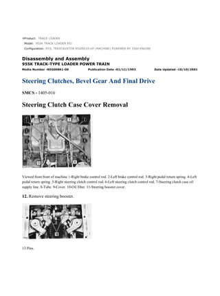
  • 1. Product: TRACK LOADER Model: 955K TRACK LOADER 85J Configuration: 955L TRAXCAVATOR 85J09510-UP (MACHINE) POWERED BY 3304 ENGINE Disassembly and Assembly 955K TRACK-TYPE LOADER POWER TRAIN Media Number -REG00861-00 Publication Date -01/11/1993 Date Updated -10/10/2001 Steering Clutches, Bevel Gear And Final Drive SMCS - 1405-016 Steering Clutch Case Cover Removal Viewed from front of machine 1-Right brake control rod. 2-Left brake control rod. 3-Right pedal return spring. 4-Left pedal return spring. 5-Right steering clutch control rod. 6-Left steering clutch control rod. 7-Steering clutch case oil supply line. 8-Tube. 9-Cover. 10-Oil filter. 11-Steering booster cover. 12. Remove steering booster. 13 Pins. 1/16 955L TRAXCAVATOR 85J09510-UP (MACHINE) POWERED BY 3304 ENGINE(... 2021/12/17 https://127.0.0.1/sisweb/sisweb/techdoc/techdoc_print_page.jsp?returnurl=/sis...
  • 2. 14-Bolts (eighteen). 15-Forged eyebolts (three). Install 3/8"-16 NC forged eyebolts and attach a hoist. 16-Steering clutch case cover. Steering Clutch And Bevel Gear Shaft Removal 1-Rod ends. When installing rod end and adjusting nut, adjust dimension between center of hole in rod end and outer face of adjusting nut to dimension shown. Lock with lock nut. 2-Bolts (twenty). 3-Bearing caps. The caps are marked L and R and should be installed on the correct side of the machine. Steering Clutch Removal 1-Lock. 2-Nut. Loosen until there is .25 in. (6,4 mm) between nut and hub. 3-Steering clutch, bearing and yoke. Pull 2/16 955L TRAXCAVATOR 85J09510-UP (MACHINE) POWERED BY 3304 ENGINE(... 2021/12/17 https://127.0.0.1/sisweb/sisweb/techdoc/techdoc_print_page.jsp?returnurl=/sis...
  • 3. the steering clutch from the shaft by using a 7F9540 Hydraulic Puller, 6F25 or 3S6224 Pump Group, 8B7548 Push Puller, two 8B7556 Adapters and an 8B7561 Step Plate. Steering Clutch Installation Be certain the splines on the bevel gear shaft and in the steering clutch driving drum are clean, dry and free from burrs. 1. With the splines meshing, push the clutch onto the shaft as far as possible by hand. 2. Using a 7M7236 Adapter Group, 7F9540 Hydraulic Puller and 6F25 or 3S6224 Pump Group, press the steering clutch driving drum onto the bevel gear shaft with a pressure of 15-20 tons (13,6 -18,1 M. tons). The distance between the face of the drum and the shoulder of the shaft must then be .12±.03 in. (3,0±0,8 mm). 3. Install the steering clutch retaining nut. Tighten to a torque of 250±50 lb. ft. (34,6±6,9 mkg). Install the lock. Steering Clutch Disassembly To remove or install locks (1) use a 7F9540 Hydraulic Puller, 6F25 or 3S6224 Pump Group, 8B7548 Push Puller, two 8B7556 Adapters, 8B7561 Step Plate and 7S8431 Spring Compressor Plate. 3/16 955L TRAXCAVATOR 85J09510-UP (MACHINE) POWERED BY 3304 ENGINE(... 2021/12/17 https://127.0.0.1/sisweb/sisweb/techdoc/techdoc_print_page.jsp?returnurl=/sis...
  • 4. NOTE: If new discs (8) are installed, no precaution is necessary as to which face is up. If the same discs are installed, they must be replaced with the same face up. Place the top discs on the bottom of the stack. Steering Clutch Release Bearing Removal And Installation 1-Setscrews (two). 2-Nut. 3-Retaining ring. 4-Thrust bearing. 5-Bearing cage and yoke. 6-Steering clutch (shown with drum installed to protect and align teeth of discs). NOTE: The bearing (4) is a thrust bearing and must be installed with the widest side of the inner race next to the nut. 1. Assemble the parts in the reverse order of disassembly. 2. After the nut has been secured, drill two diametrically opposed 13/64 in. holes, .38 in. (9,6 mm) deep on the parting line of the plate assembly and the nut. 3. Using a 1/4"-20 NC tap, tap each hole .25 in. (6,3 mm) deep. 4. Install the two hollow head setscrews. 5. Peen over the nut and plate assembly around the setscrews to retain them. Bevel Gear Shaft Bearings And Bevel Gear Removal 1-Cage, nut and cup. 2-Bearing. The bevel gear shaft bearings can be removed by using an 8B7548 Push Puller, 8B7549 Legs, 8B7551 Bearing Puller Attachment, 7F9540 Hydraulic Puller and a 6F25 or 3S6224 Pump Group. 3- Nuts (eight). 4-Bolts (eight). 5-Bevel gear. NOTE: Heat the bearings in oil before installing on shaft. The inner race must be seated against the shoulder of the shaft. 4/16 955L TRAXCAVATOR 85J09510-UP (MACHINE) POWERED BY 3304 ENGINE(... 2021/12/17 https://127.0.0.1/sisweb/sisweb/techdoc/techdoc_print_page.jsp?returnurl=/sis...
  • 5. Bevel Gear And Pinion Setting The bevel gear and pinion must be located to obtain the correct tooth contact. The pinion can be moved toward or away from the centerline of the bevel gear and bevel gear shaft with shims located between the pinion shaft bearing cage and the bevel gear case. Adjusting nuts, on each bevel gear shaft bearing cage, permit moving the bevel gear toward or away from the centerline of the bevel pinion shaft. Moving either the bevel gear or the pinion affects both backlash and tooth contact so the two must be adjusted at the same time. The relative positions of the bevel gear and the pinion gear will vary with different sets. The correct amount of backlash is .008 ± .003 in. (0,2± 0,07 mm). When replacing an individual gear or pinion, see the topic, BACKLASH ADJUSTMENT, for correct setting. The pinion location can be obtained as described in the topic, BEVEL PINION LOCATION. Preload the bevel gear shaft bearings as outlined in the covering topic before adjusting the backlash or locating the bevel pinion. Bevel Gear Shaft Bearing Preload Typical example of bevel gear shaft bearing preload. Illustrated are : 1-7M7239 Wrench. 2-Nut. 3-Nut. Use a 7M7239 Wrench to tighten the nuts. Make certain the bevel gear and bevel pinion gear do not bind. Use a pry bar to make certain there is no bevel gear shaft bearing end clearance. Backlash Adjustment The amount of backlash between each bevel gear and pinion set on original installation, is determined at the factory and marked on the outside diameter of the bevel gear. On a replacement gear or pinion, adjust the backlash to .008±.003 in. (0,2±0,07 mm). 1. Secure a dial indicator to the bevel gear case as shown. 2. Lock the bevel gear so it cannot rotate. 3. Place the finger of the dial indicator on the pinion gear tooth. 4. Rock the pinion gear back and forth. 5/16 955L TRAXCAVATOR 85J09510-UP (MACHINE) POWERED BY 3304 ENGINE(... 2021/12/17 https://127.0.0.1/sisweb/sisweb/techdoc/techdoc_print_page.jsp?returnurl=/sis...
  • 6. 5. The amount of backlash is the difference in readings on the dial indicator. 6. Check the backlash at four different locations on the bevel gear, taking the lowest reading as the position to check the backlash. 7. If the reading is too great, decrease the backlash by loosening the right adjusting nut and tightening the left adjusting nut an equal amount. Typical example of checking bevel gear backlash. Illustrated are: 1-Left adjusting nut. 2-Right adjusting nut. 8. To increase backlash, loosen the left adjusting nut and tighten the right adjusting nut an equal amount. NOTE: Bevel gear shaft bearing preload will be maintained only if the bearing slack caused by loosening one adjusting nut is compensated for by tightening the other adjusting nut an equal amount. See the topic, BEVEL GEAR SHAFT BEARING PRELOAD. 9. If the notches on the adjusting nuts and bearing cage caps are not aligned, turn the nuts to the nearest notch and install the locks. After adjusting the bevel gear, tighten the bolts holding the bearing caps and lock them in place. Tighten and lock the bolts that secure the bevel pinion gear bearing cage to the bevel gear case. Bevel Pinion Location If the same pinion shaft is reinstalled in the same bevel gear case, use the same shims between the pinion shaft bearing cage and the bevel gear case that were removed. The pinion can be located by observing the tooth contact pattern made by the pinion gear teeth on the bevel gear teeth. This can be done in the following manner. Use sufficient shims between the pinion shaft bearing cage and the bevel gear case to align the heel ends of the bevel gear and pinion gear teeth. This will place the pinion in nearly the correct relationship with the bevel gear. 6/16 955L TRAXCAVATOR 85J09510-UP (MACHINE) POWERED BY 3304 ENGINE(... 2021/12/17 https://127.0.0.1/sisweb/sisweb/techdoc/techdoc_print_page.jsp?returnurl=/sis...
  • 7. This illustrates aligning the bevel gear and pinion. Adding shims will move the pinion gear away from the centerline of the bevel gear shaft. Removing shims will move the pinion toward the centerline of the bevel gear shaft. Adjust the bevel gear backlash as described in the topic, BACKLASH ADJUSTMENT. This should give a very close adjustment. To further check the adjustment, brush Prussian blue or red lead sparingly on the bevel gear teeth. When the pinion is rotated, the red lead is squeezed away by the contact of the teeth, leaving bare areas of the contacts. Sharper impressions can be obtained by applying a small amount of resistance to the bevel gear while rotating the pinion. When making adjustments, check the convex side of the bevel gear teeth. The reverse or concave side contact should automatically be correct when the convex side is correct. FIG. A - This illustrates proper tooth contact pattern. With adjustments properly made, the correct tooth contact in Fig. A will be obtained. The area of contact starts near the toe of the gear and extends about 30 per cent of the tooth length. This contact pattern is obtained with no load applied to the gears. This adjustment results in a quiet running bevel gear and pinion set which, because when the load is applied it is distributed over the teeth within the proper area, will give maximum service life. It is permissible for the tooth contact area to be slightly greater on the concave face. 7/16 955L TRAXCAVATOR 85J09510-UP (MACHINE) POWERED BY 3304 ENGINE(... 2021/12/17 https://127.0.0.1/sisweb/sisweb/techdoc/techdoc_print_page.jsp?returnurl=/sis...
  • 8. FIG. B - This illustrates short toe contact. In Fig. B, the pinion is too far away from the centerline of the bevel gear shaft. This causes the teeth to bear on the toe ends of the convex faces and toward the heel end of the concave faces. To correct this, move the pinion toward the gear by removing shims from the bevel pinion bearing cage. Recheck the backlash, changing it if necessary, and again check the tooth contact pattern. To correct the backlash, move the bevel gear away from the pinion. FIG. C - This illustrates short heel contact. In Fig. C, the pinion is too close to the centerline of the bevel gear shaft. This causes the teeth to bear on the toe ends of the concave faces and the heel ends of the convex faces. To correct, add shims to the bevel pinion bearing cage. Then, recheck the backlash and tooth contact patterns. To correct the backlash, move the bevel gear toward the pinion. Several adjustments of both the pinion and bevel gear may be necessary before correct tooth contact and backlash are obtained. Always remember that the backlash will also affect the tooth contact pattern. Therefore, be sure the backlash is properly adjusted before checking the adjustment of the pinion. Brake Band And Drum Removal And Installation 1-Brake drum. 2-Brake band. 8/16 955L TRAXCAVATOR 85J09510-UP (MACHINE) POWERED BY 3304 ENGINE(... 2021/12/17 https://127.0.0.1/sisweb/sisweb/techdoc/techdoc_print_page.jsp?returnurl=/sis...
  • 9. Final Drive Pinion Removal 1-Nut. 2-Lock. After removing lock, reinstall nut leaving about .25 in. (6,3 mm) between flange and nut. 3-Bolts (six). 4-3/8"-16 NC forged eyebolt and nut. Attach a hoist. Move the flange and pinion toward the centerline of the machine until the cage clears the inside wall of the clutch case and the flange and pinion can be supported as shown. 5-Brake drum flange. Remove from pinion by using an 8B7548 Push Puller, two 8B7556 Adapters, an 8B7560 Step Plate, a 7F9546 Hydraulic Puller and a 6F25 or 3S6224 Pump Group. Final Drive Pinion Disassembly 1 Remove dowel by inserting a 1/4"-20 NC bolt into the dowel and pulling the dowel out of the cage. 2 Remove the races with an 8B7548 Push Puller, 8B7551 Bearing Pulling Attachment and an 8B7560 Step Plate. Final Drive Pinion Installation Reassemble the final drive pinion and install it in the machine. Press the brake drum flange into place with a force of 15-20 tons (13,6-18,1 M. tons) using a 7M7236 Adapter Group, 7F9540 Hydraulic Puller and a 6F25 or 3S6224 Pump Group. 9/16 955L TRAXCAVATOR 85J09510-UP (MACHINE) POWERED BY 3304 ENGINE(... 2021/12/17 https://127.0.0.1/sisweb/sisweb/techdoc/techdoc_print_page.jsp?returnurl=/sis...
  • 10. The distance between the face of the flange and the shoulder of the pinion should be .12±.03 in. (3,0±0,7 mm). Final Drive Removal And Installation (As A Unit) 1-Cap. 2-Lock. 3-Nut. 4-Washer. 5-Bearing. 10/16 955L TRAXCAVATOR 85J09510-UP (MACHINE) POWERED BY 3304 ENGIN... 2021/12/17 https://127.0.0.1/sisweb/sisweb/techdoc/techdoc_print_page.jsp?returnurl=/sis...
  • 11. 6-Shims. For alignment of track roller frame and sprocket. See ALIGNMENT OF TRACK ROLLER FRAMES. 7- Holder, and bearing cage. 8-Adjusting nut. NOTE: Replace the nut (3) on the end of the sprocket shaft leaving some space between it and the end of the bearing cage holder. The holder assembly (7) can be removed by turning the nut (8) in a clockwise direction with a 7F9306 Spanner Wrench. 9-Duo-Cone floating seals (two). Remove the Duo-Cone floating seals for their protection. Use 9M5143 Seal Installer to remove or install Duo-Cone seals. One is in the retainer on the sprocket. The other is in a retainer in the adjusting nut. See the GENERAL INSTRUCTIONS for seal removal and installation. 10-Bolts (twenty-four). 11. Attach a hoist to the sprocket. Use two 3/8" -16 NC forcing screws to separate the final drive case from the steering clutch case. Final Drive Removal And Disassembly 11/16 955L TRAXCAVATOR 85J09510-UP (MACHINE) POWERED BY 3304 ENGIN... 2021/12/17 https://127.0.0.1/sisweb/sisweb/techdoc/techdoc_print_page.jsp?returnurl=/sis...
  • 12. Sprocket Segment Removal And Installation 1. Remove sprocket guards. 2. Remove bolts and nuts (2) and remove sprocket segment (1). 12/16 955L TRAXCAVATOR 85J09510-UP (MACHINE) POWERED BY 3304 ENGIN... 2021/12/17 https://127.0.0.1/sisweb/sisweb/techdoc/techdoc_print_page.jsp?returnurl=/sis...
  • 13. 3. At installation place machined side of segment (1) towards hub and head of retaining bolt against inside of hub. 4. Lubricate threads of bolts with high pressure lubricant or 9M3710 Anti-Seize Compound and tighten all nuts to 130 ± 30 lb. ft. (19,0 ± 4,1 mkg), then tighten each nut an additional 1/3 turn. See Tool Selection Chart for tools to remove solid sprocket hubs on later machines. 1, 3, 6 Remove dowels by inserting 1/4"-20 NC bolt into the dowels and pulling them out of the housing. 2 Use two 3/8"-16 NC forcing screws to separate final drive case from steering clutch case. 4 Remove bearings with an 8B7554 Puller and an 8B7552 Forcing Bolt. 5 Remove inner races by heating evenly with a torch so they will expand. 7 Remove cone using an 8H705 Puller. 8 Remove cup by arc welding a bead around its inside diameter causing it to shrink. Install new cup by chilling and driving into bore. NOTICE Make certain the ground lead is connected to the bevel gear case to prevent arcing through bearings. 9 Remove the sprocket shaft by removing the retainer nut under the steering clutch case and by using a 6F25 or 3S6224 Pump Group, 7F9831 Cylinder Group, 5F9888 Coupling Adapter, 5F9879 Adapter, 5F9892 Pin and a 5F9890 Sprocket Shaft Puller Group. 10 Remove cone by forcing it off the hub with the sprocket retaining nut. Use a 5F9693 Wrench, to turn the nut. Heat the cone to install on hub. 11 Use nut to force off cone then reinstall nut so there is about .25 in. (6,3 mm) between it and the sprocket. Be sure that the nut is installed as stated in item 11 to prevent the sprocket from jumping off the hub after it has broken loose from the press fit. 12 Remove sprocket using a 6F25 or 3S6224 Pump Group, 7F9831 Cylinder Group, 5F7694 Plug, three 5F9040 Arm Groups and two 7S9484 Spacer assemblies. 13/16 955L TRAXCAVATOR 85J09510-UP (MACHINE) POWERED BY 3304 ENGIN... 2021/12/17 https://127.0.0.1/sisweb/sisweb/techdoc/techdoc_print_page.jsp?returnurl=/sis...
  • 14. 13 Shims used to align track roller frame with sprocket. See TRACK ROLLER FRAME ADJUSTMENT. 14 Replace sprocket shaft nut on the sprocket shaft with some space between it and the holder assembly (14). This prevents the holder assembly from jumping off the shaft after it has broken loose from the taper fit. Turn the final drive adjusting nut clockwise with a 7F9306 Spanner Wrench to remove the bearing cage holder assembly. 15 Use a 9M5143 Seal Installer to remove or install Duo-Cone seals. Final Drive Assembly Sprocket Shaft Installation Using a 5F9889 Plug, 5F9885 Adapter (threaded against the shoulder on the sprocket shaft), and a 5F9892 Pin, drive the sprocket shaft into the bevel gear case (with the key slot facing upward) until the distance between the face of the outer bearing cage holder (hand held in place on the taper of the sprocket shaft) and the parting line between the final drive case and the bevel gear case is 10.34±.062 in. (262,64±1,57 mm). 14/16 955L TRAXCAVATOR 85J09510-UP (MACHINE) POWERED BY 3304 ENGIN... 2021/12/17 https://127.0.0.1/sisweb/sisweb/techdoc/techdoc_print_page.jsp?returnurl=/sis...
  • 15. Install the sprocket shaft retainer nut and tighten securely. To lock in place, drill a 5/16" hole through one of the notches in the nut through the nut and into the shaft to a total depth of 1.14 in. (30,2 mm). This drawing shows locking of the sprocket shaft retaining nut. C-5/16" drill, 1.14 in. (30,2 mm) deep. Place the pin in the hole and install the snap ring to hold the pin in place. Sprocket Installation To install the sprocket use a 5F9879 Adapter, 5F9888 Coupling Adapter, 7F5288 Pusher Group, 7F9831 Cylinder Group, 5F9892 Coupling Pin and a 6F25 or 3S6224 Pump Group. Press the sprocket onto the hub with a pressure of 35-40 tons (31,7-36,3 M. tons). The distance between the face of the sprocket hub and the shoulder of spline should be .12±.06 in. (3,0±1,5 mm). 15/16 955L TRAXCAVATOR 85J09510-UP (MACHINE) POWERED BY 3304 ENGIN... 2021/12/17 https://127.0.0.1/sisweb/sisweb/techdoc/techdoc_print_page.jsp?returnurl=/sis...
  • 16. Final Drive Bearing Preload Adjustment Preload the final drive bearings by turning the adjusting nut counterclockwise with a 7F9306 Spanner Wrench. Apply a torque of 1050±150 lb. ft. (145,2±20,7 mkg). For an illustrated step-by-step procedure, see the MAINTENANCE GUIDE. 16/16 955L TRAXCAVATOR 85J09510-UP (MACHINE) POWERED BY 3304 ENGIN... 2021/12/17 https://127.0.0.1/sisweb/sisweb/techdoc/techdoc_print_page.jsp?returnurl=/sis...
  • 17. Product: TRACK LOADER Model: 955K TRACK LOADER 85J Configuration: 955L TRAXCAVATOR 85J09510-UP (MACHINE) POWERED BY 3304 ENGINE Disassembly and Assembly 955K TRACK-TYPE LOADER POWER TRAIN Media Number -REG00861-00 Publication Date -01/11/1993 Date Updated -10/10/2001 Undercarriage SMCS - 1405-016 Relieving Track Tension Be certain the hydraulic pressure in the track adjusting mechanism is completely relieved and the cylinder can be moved to the rear into the recoil spring front pilot before attempting to separate the track or remove the track adjusting mechanism. Release the pressure in the hydraulic track adjuster cylinder, WITH CAUTION as given in the following steps: This is a view of the hydraulic track adjuster. Items indicated are: 1-Relief valve. 2-Fill valve. 3-Vent holes. 4-Cylinder. 5-Recoil spring front pilot. Because of the hydraulic pressure in the track adjuster cylinder, never visually inspect the vent holes and valves to see if lubricant is escaping. 1/14 955L TRAXCAVATOR 85J09510-UP (MACHINE) POWERED BY 3304 ENGINE(... 2021/12/17 https://127.0.0.1/sisweb/sisweb/techdoc/techdoc_print_page.jsp?returnurl=/sis...
  • 18. Always observe the cylinder to see that it moves to the rear into the recoil spring front pilot. 1. Turn relief valve counterclockwise one turn to allow lubricant to escape from vent hole just below RELIEF valve. Wait momentarily. If the cylinder does not retract turn FILL valve counterclockwise one turn. 2. If the cylinder does not retract into the front pilot, loosen the RELIEF valve until it contacts the underside of the guard. Lubricant should escape through slot in the lower section of threads. 3. If the cylinder does not retract loosen FILL valve until it contacts the underside of the guard. Lubricant should then escape through slot in the lower section of threads. 4. If the cylinder does not retract into the front pilot, the machine should be started and moved forward and backward. 5. If moving the machine does not cause the cylinder to retract, insert a draw bar pin between the track and sprocket. Move the machine backward so the track will be forced upward by the pin. This will apply additional tension to the track. This is a drawing of the track adjuster mechanism. The items indicated are: 1-Relief valve. 2-Fill valve. 3-Vent holes. 6- Slots. A-Unthreaded section, relief valve. B-Unthreaded section, fill valve. Separating Track 1. Relief track tension. 2. Remove the master pin using the 2S8210 Track Tool Group. 3. Separate the track. 2/14 955L TRAXCAVATOR 85J09510-UP (MACHINE) POWERED BY 3304 ENGINE(... 2021/12/17 https://127.0.0.1/sisweb/sisweb/techdoc/techdoc_print_page.jsp?returnurl=/sis...
  • 19. 4-Spacers (two). 5-Coned disc seal washers (four). 6-Master links (two). 7. Back the machine slowly, allowing the track to ride over the carrier roller and off the sprocket. Track Disassembly 1 At assembly tighten track shoe bolts to a torque of 130 ± 30 lb. ft. (18 ± 4,1 mkg) plus an additional 1/3 turn. Install nuts with rounded corners next to the track link. 3 Remove and install pins with 2S8210 Track Tool Group. 4 Remove and install bushings with 2S8210 Track Tool Group. When installing the master bushing the ends should be flush with the outside faces of the links. Other bushings should protrude past the outside face of the links .321 ± .005 in. (8,15 ± 0,13 mm). Installing Track 1. Back the machine until the sprocket is just ahead of the master links of the track. 2. Insert a bar into the links and help the track climb over the sprocket. Drive the machine forward slowly. 3/14 955L TRAXCAVATOR 85J09510-UP (MACHINE) POWERED BY 3304 ENGINE(... 2021/12/17 https://127.0.0.1/sisweb/sisweb/techdoc/techdoc_print_page.jsp?returnurl=/sis...
  • 20. Always hold the bar as illustrated. 3. Continue to carry the track over the rollers and front idler. Carry track high enough to clear carrier rollers. 4. Place a block under the first shoe, drive forward until master links and track links are about 1 in. (25,4 mm) apart. Install the coned disc seal washers and spacer in each master link. This drawing shows the installation of coned disc seal washers and spacers. The parts pointed out are: 1-Spacers (two). 2 and 3-Coned disc seal washers (four). 4-Master links (two). 5-Track links (two). 5. Install each set of coned disc seal washers (as shown) with the inside diameters in contact. Install spacers (as shown) with beveled edges toward one another. 4/14 955L TRAXCAVATOR 85J09510-UP (MACHINE) POWERED BY 3304 ENGINE(... 2021/12/17 https://127.0.0.1/sisweb/sisweb/techdoc/techdoc_print_page.jsp?returnurl=/sis...
  • 21. 6. Assemble FT573 Holding Tool (Fabricated Tool) onto master links and tighten each bolt to compress seal washers. The spacers will be flush with inner face of links when seal washers are properly compressed. 7. Move the machine forward and drive the track together until the spacers are held in place by track links. 8. Remove the holding tool. Align the holes and install the master pin. 9. Adjust the track tension. See MAINTENANCE GUIDE. Track Roller Frame Removal And Installation 1-Bolts (four). 2-Bolts. At installation lubricate threads with a thick mixture of oil and flowers of sulphur or an equivalent lubricant. 3-Bolts (nine). At installation lubricate threads with a thick mixture of oil and flowers of sulphur or an equivalent lubricant. 4-Shims. For parallel alignment of track roller frames. 5-Bolts (six). At installation lubricate threads with a thick mixture of oil and flowers of sulphur or equivalent lubricant. 6. Raise the side of the machine about 6 in. (152,4 mm); block securely. Remove the track roller frame by rolling it forward along the track. 5/14 955L TRAXCAVATOR 85J09510-UP (MACHINE) POWERED BY 3304 ENGINE(... 2021/12/17 https://127.0.0.1/sisweb/sisweb/techdoc/techdoc_print_page.jsp?returnurl=/sis...
  • 22. 7-Track roller frame replaceable wear strips. Alignment Of Track Roller Frames Aligning Track Roller Frame with Sprocket The items involved in aligning the sprocket and track roller frame are: 1-Rear track roller. 2-Drive sprocket. A- Clearance. B-Clearance. 1. Center the recess of the rear track roller so the clearances between the sprocket and either edge of the track roller rim are equal. 2. Add shims (see FINAL DRIVE DISASSEMBLY) between the washer assembly and the holder assembly to move the roller frame out, decreasing the clearance (A). Remove shims between the washer assembly and the holder assembly to allow the roller frame to move in, decreasing clearance (B). Parallel Alignment of Track Roller Frames 1. Align the track roller frames with the sprockets. 2. Measure the distance between the insides of the track roller frame channels at the rear. 6/14 955L TRAXCAVATOR 85J09510-UP (MACHINE) POWERED BY 3304 ENGINE(... 2021/12/17 https://127.0.0.1/sisweb/sisweb/techdoc/techdoc_print_page.jsp?returnurl=/sis...
  • 23. Suggest: For more complete manuals. Please go to the home page. https://www.ebooklibonline.com If the above button click is invalid. Please download this document first, and then click the above link to download the complete manual. Thank you so much for reading
  • 24. The parts involved in parallel adjustment are: 1-Track roller frame. 2-Loader frame support. 3-Shims. 3. Measure the distance between the insides of the track roller frame channels just in front of the loader frame support. 4. Install shims between each end of the loader frame support and the roller frames so the distance in front is within .12 in. (3,05 mm) of the distance measured at the rear. 5. Install and tighten the bolts securing the loader frame support to the track roller frames and again check the distances. The items involved in parallel adjustment of the track roller frames are: 1-Track roller frame. 2-Loader frame support. 3- Shims. A-Distance between roller frames at front. B-Distance between roller frames at rear. Front Idler Removal And Installation 7/14 955L TRAXCAVATOR 85J09510-UP (MACHINE) POWERED BY 3304 ENGINE(... 2021/12/17 https://127.0.0.1/sisweb/sisweb/techdoc/techdoc_print_page.jsp?returnurl=/sis...
  • 25. 1-Bolts (four). Loosen until spring pressure is relieved. 3-Front idler. Attach hoist and remove by moving forward. 4-Plates (two). 5-Spring assemblies (four). 6-Plates (four). Front Idler Disassembly 1 Apply 9M3710 Anti-Seize Compound in bearing bores and on bearing contact surfaces of shaft. 2 Tighten bolts to a torque of 40 lb. ft. (5,5 mkg). Seat tapered lockpins with a punch and hammer, then retighten bolts to a torque of 50 ± 10 lb. ft. (6,9 ± 1,3 mkg). 3 Oil hole on plug end of shaft to be assembled up. 4 Coat the outside diameter of the bushing assemblies with white lead. Use FT578 Alignment Tool Group (Fabricated Tool) to insure alignment of bolt holes. 5 Use 5M2196 Seal Installer to remove and install Duo-Cone seals. 6, 8 Use shims to align the front idler with the track. If the idler is too far toward the outside, move shims from the bearing at the inner end of the idler hub to the outer bearing. If the idler is too far toward the inside, reverse the process. After alignment, .06 in. (1,52 mm) should be maintained between each plate and track roller frame by using shims. 8/14 955L TRAXCAVATOR 85J09510-UP (MACHINE) POWERED BY 3304 ENGINE(... 2021/12/17 https://127.0.0.1/sisweb/sisweb/techdoc/techdoc_print_page.jsp?returnurl=/sis...