
Recommended
More Related Content
Similar to A385992265_25184_26_2019_UNIT-1b Sensor_characteristics_and_Fundamentals (1).ppt
Similar to A385992265_25184_26_2019_UNIT-1b Sensor_characteristics_and_Fundamentals (1).ppt (20)
Recently uploaded
Recently uploaded (20)
A385992265_25184_26_2019_UNIT-1b Sensor_characteristics_and_Fundamentals (1).ppt
- 2. Unit-1b: Smart Sensor Sensor Characteristics: There are various conversion steps which are performed before an electrical signal is generated in a sensor from a given stimulus. Take for example a pressure detection with optical fiber. 1. Pressure produce a strain in the fiber 2. That changes the refractive index of the fiber material 3. That changes the optical transmission and modulation of the photon density 4. Then the modulated photon density is detected and converted into an electrical signal using photoresistive phenomenon etc. If there are lots of conversions, then we must have some way to estimate the output at every conversion.
- 3. Sensor Characterization continued ) (s f S This function can be a linear or exponential or some other complex function. But in many cases it’s a linear function of the type bs a S Here a is the intercept and b is the slope or it is also called sensitivity. s S Input Output 1. Transfer function. There is an ideal or a theoretical relationship between the stimulus and output it generate. This ideal function could a table of values or a graph or a mathematical equation. This ideal output-stimulus relationship is called a transfer function. This relationship describes the dependence of the a stimulus s on the electrical signal S.
- 4. Transfer Function and Accuracy limits
- 5. 2. Span (Input full scale) The dynamic range of stimuli which may be converted by a sensor is called a span or an input full scale (FS). It represents the highest possible input value which can be applied to a sensor. This dynamic range is often expressed in decibels which is a logarithmic measure of ratios of either power or voltage. 3. Full Scale Output (FSO) The algebraic difference between the end points of the outputs for maximum input and lowest input stimulus. The upper limit of a sensor output over the measured range is called the full scale. 1 2 log 10 1 P P dB Sensor Characterization continued s S Input Output FSO
- 6. 3. Accuracy Accuracy of a sensor really means inaccuracy, that is the highest deviation of a value from its ideal value. 4. Calibration Error Calibration Error is inaccuracy permitted by a manufacturer when a is calibrated in the factory. This is a systematic error which is added to all possible real transfer function. 5. Hysteresis The maximum difference in output, at any measured value, within the measured range when the value is approached first with increasing and decreasing measurand. It is expressed in % of FSO during one calibration cycle. Sensor Characterization continued Hysteresis
- 7. Sensor Characterization continued Nonlinearity error is specified for sensors whose transfer function may be approximated by a straight line. So it measures a maximum deviation (L) of a real transfer function from the approximate straight line The value of measurand over which the sensor is intended to measure specified by upper and lower limits. 7. Measurand Range 6. Nonlinearity
- 8. 8. Resolution. The minimum change of the measurand value necessary to produce a detectable change at the output. 9. Selectivity The ability of a sensor to measure one measurand ( e,g., one chemical component ) in the presence of others. Sensor Characterization continued 10. Sensitivity. The ratio of the change in sensor output to the change in the input of a measurand. It is the slope of the transfer curve. o s s ds s dS b ) ( 11. Ambient Conditions Allowed Ambient conditions can strongly influence the operation of a sensor. These conditions include temperature, moisture, ambient pressure, vibrations, shock, acceleration and EM field.
- 9. Electrical and other fundamentals: Electric charges, field and potentials: We consider interaction between charges mainly in the following mediums : • Conductors, • Semiconductors • Insulators • Fluids These materials are characterized by their electric properties, like dielectric constant, resistivity etc.
- 10. Electric Charges, Fields, and Potentials • Positive test charge in vicinity of a charged object • (a) and electric field of a spherical object (b) • If a small positive electric test charge q0 is positioned in the vicinity of a charged object, it will be subjected to a repelling electric force
- 11. Gauss’ law • If we imagine a hypothetical closed surface (Gaussian surface) S, a connection between the charge q and flux can be established as where the integral is equal to If a surface encloses equal and opposite charges, the net flux is zero. The charge outside the surface makes no contribution to the value of q, nor does the exact location of the inside charges affect this value. The Coulomb law itself can be derived from the Gauss’ law. It states that the force acting on a test charge is inversely proportional to a squared distance from the charge
- 12. How to calculate an electric field at a given point in a medium? The Gauss’ law Q dS E o . =total charge enclosed within that surface) Q E dS E=electric field dS is the surface element Examples: How to calculate the electric field of the following charge distributions? • Spherical symmetric charge distribution Q dS E o . Q r E o 2 4 Total surface area of a sphere = 2 4 r +Q 2 4 1 r Q E o
- 13. +Q r Inside a uniform sphere of charge Q R dS E o . charge enclosed within the radius r of the big sphere of radius R 3 3 2 4 R r Q r E o 3 4 1 R Qr E o the electric field inside a uniform sphere of charge q is directed radially and has magnitude
- 14. Infinite Charged Line We construct a Gaussian surface, which is a ring of radius r around the wire. is the charge per unit length of the wire.wire Note that the electric field varies as r 1 If the electric charge is distributed along an infinite (or, for the practical purposes, long) line, the electric field is directed perpendicularly to the line and has the magnitude where r is the distance from the line and l is the linear charge density (charge per unit length).
- 15. Electric field near an infinite sheet The electric field due to an infinite sheet of charge is perpendicular to the plane of the sheet and has magnitude
- 16. Electric filed between the two charged sheets or between parallel plate condensers ++ + + + + + - - - - - - - Electric field E is directed from one sheet to another o o o E E E 2 2
- 17. Electric dipole (a); an electric dipole in an electric field is subjected to a rotating force (b) An electric dipole is a combination of two opposite charges which are placed at a distance 2a apart. Each charge will act on a test charge with force which defines electric fields E1 and E2 produced by individual charges. A combined electric field of a dipole, E, is a vector sum of two fields. The magnitude of the field is where r is the distance from the center of the dipole Where dipole moment p =2qa
- 18. Electric potential: It is the amount of work done per unit charge against the external electric field to bring a charge to a particular point r in a medium. That defines the electric potential associated with that point. A Charge Q B Electric field E B A V V -work done =-F.dr =- E.dr B A o B A o r r Q r Q dr V 1 1 4 4 1 2 Potential at a distance r from the charge +Q is r Q V o 4 1 One can obtain this if we take the point B to infinity and assume rA = r Units of the potential are Volt = Joule/Coulomb dr E V . Since E dr dV Gradient of potential gives the electric field
- 19. Capacitance V Q C Capacitance is defined as On what factors the value of C depends? Medium between the plates, shape of the plates, distance between the plates Fluctuating current C j i V 1 Electric field E A= area of the plate + + + + + + - - - - - - +Q -Q Voltage applied =V + - d The phenomenon of a capacitance is used in many sensors.
- 20. Capacitance continued Capacitance between the two parallel plates can also be defined as d A C 0 It is the capacitance dependence of the above factors which is exploited in most of the sensors design. For a cylindrical capacitor a b L C ln 2 0 L +Q -Q a b
- 21. Dielectric Constant The presence of a medium between the plates of a capacitor modifies the electric field between the plates. So the effective dielectric constant becomes d A C V Q C 0 0 One can think of making a sensor where k is changes by a stimulus. Think also of series and parallel capacitors
- 22. Dielectric Constant of Water vs Temperature
- 23. Capacitive water level sensor (A); capacitance as function of the water level
- 24. Another Example of Capacitor • Another example of a capacitive sensor is a humidity sensor. • In such a sensor, a dielectric between the capacitor plates is fabricated of a material that is hygroscopic, that is, it can absorb water molecules. • Material dielectric constant varies with the amount of absorbed moisture, this changes the capacitance that can be measured and converted to a value of relative humidity The dependence is not perfectly linear but this usually can be taken care of during the signal processing
- 25. RH estimation by Dry & Wet Bulb Relative Humidity - RH (%) Tdb - Twb (oC) Dry Bulb Temperature - Tdb (oC) 15 18 20 22 25 27 30 33 1 90 91 91 92 92 92 93 93 2 80 82 83 84 85 85 86 87 3 71 73 75 76 77 78 79 80 4 62 65 67 68 70 71 73 74 5 53 57 59 61 64 65 67 69 6 44 49 52 54 57 59 61 63 7 36 42 45 47 51 53 55 58 8 28 34 38 41 45 47 50 53 9 21 27 31 34 39 41 45 48 10 13 20 25 28 33 36 40 43
- 26. Resistance Resistance of a material is defined as i V R a = area of cross-section of the material Temperature dependence of resistivity ) ( 1 o o T T •Resistivity of a material can be expressed through •mean time between collisions, τ, •the electronic charge, e, •the mass of electron, m, and •a number of conduction electrons per unit volume, n
- 27. Specific Resistance of Materials
- 28. Moisture Sensitivity • By selecting material for a resistor, one can control its specific resistivity and susceptibility of such to the environmental factors. • One of the factors that may greatly affect r is the amount of moisture that can be absorbed by the resistor. • A moisture-dependent resistor can be fabricated of a hygroscopic material whose specific resistivity is strongly influenced by concentration of the absorbed water molecules. • This is the basis for the resistive humidity sensors, which are called hygristors. A typical hygristor is comprised of a ceramic substrate that has two silk-screen printed conductive inter-digitized 7 electrodes
- 29. Piezoelectric effect It is generation of electric charge by a crystalline material when subjected to an external stress. Example of materials: Quartz ( chemical formula SiO2, , man made ceramics and some polymers, such as PVDF How the charges are created? To pick up the electric field, conductive electrodes must be applied to the opposite side of the crystal cut. As a result a piezoelectric material becomes a capacitor with voltage V across the capacitor.
- 30. The word piezo comes from the Greek meaning “to press.” • The Curie brothers discovered the piezoelectric effect in quartz in 1880, but very little practical use was made until 1917 when another Frenchman, professor P. Langevin used x-cut plates of quartz to generate and detect sound waves in water. • His work led to the development of sonar.
- 31. Piezoelectric effect is a reversible phenomenon. Which means that the applied voltage across the material will produce a strain. The polarization vector P is given by zz yy xx P P P P Piezoelectric effect Piezoelectric sensor is formed by applying electrodes to a poled crystalline material
- 32. zz yy xx xx d d d P 13 12 11 zz yy xx yy d d d P 23 22 21 zz yy xx zz d d d P 33 32 31 When we apply a stress to the crystal we generate polarization. Let dij are the piezoelectric coefficient along the orthogonal directions. Then Charge generated by a piezoelectric crystal is proportional to applied force. x x F d Q 11 For x-direction Voltage generated in a Piezoelectric crystal
- 33. So the voltage developed will be x F C d C Qx V 11 l a C o Capacitance can be written in terms of the electrode surface area , a, and thickness l Then the output voltage becomes x o x F a l d F C d V 11 11
- 34. Piezoelectric Sensor is AC or DC Device? • When stress is applied, or air blows near its surface the balanced state is degraded and the piezoelectric material develops an electric charge. • If the stress is maintained, the charges again will be neutralized by the internal leakage. • Thus, a piezoelectric sensor is responsive only to a changing stress rather than to a steady level of it. • In other words, a piezoelectric sensor is an AC device, rather than a DC device. • The three most popular materials are zinc oxide (ZnO), aluminum nitride (AlN), and the so-called solid solution system of lead-zirconite-titanium oxides Pb(Zr,Ti)O3 known as PZT ceramic
- 36. Piezoelectric Sensor for Sound waves
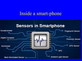
- 37. Sensor inside..
- 38. Which material preferred? • Zinc oxide in addition to the piezoelectric properties also is pyroelectric. It was the first and most popular material for development of ultrasonic acoustic sensors, surface acoustic wave (SAW) devices, microbalances, etc. One of its advantages is the ease of chemical etching. The zinc oxide thin films are usually deposited on silicon by employing the sputtering technology. • Aluminum nitride (AlN) is an excellent piezoelectric material because of its high acoustic velocity and its endurance in humidity and high temperature. Its piezoelectric coefficient is somewhat lower than in ZnO but higher than in other thin-film piezoelectric materials, excluding ceramics. The high acoustic velocity makes it an attractive choice in the GHz frequency range.
- 39. • Usually, the AlN thin films are fabricated by using the chemical vapor deposition (CVD) or reactive molecular beam epitaxy (MBE) technologies. However, the drawback of using these deposition methods is the need for high heating temperature (up to 1,300C) of the substrate. • The PZT thin films possess a larger piezoelectric coefficient than ZnO or AlN, and also a high pyroelectric coefficient, which makes it a good candidate for fabrication of the thermal radiation detectors. • A great variety of deposition techniques is available for the PZT, among which are the electron-beam evaporation [11], RF sputtering [12], ion-beam deposition [13], epitaxial growth by RF sputtering [14], magnetron sputtering [15], laser ablation [16], and sol-gel [17] Which material preferred?
- 40. Polymer Piezoelectric Films • In 1969, H. Kawai discovered a strong piezoelectricity in polyvinylidene fluoride (PVDF) and in 1975 the Japanese company Pioneer, Ltd. developed the first commercial product with the PVDF as a piezoelectric loudspeakers and earphones. • PVDF is a semicrystalline polymer with an approximate degree of crystallinity of 50%
- 41. Some unique properties of the piezoelectric films are (from Measurement Specialties Inc., www.msiusa.com) • Wide frequency range - 0.001 Hz to 109 Hz. • Vast dynamic range (10-8 to 106 psi or micro-torr to Mbar). • Low acoustic impedance – close match to water, human tissue and adhesive systems. • High elastic compliance. • High voltage output – 10 times higher than piezo ceramics for the same force input. • High dielectric strength – withstanding strong fields (75 V/micro-m) where most piezo ceramics depolarize. • High mechanical strength and impact resistance (109—1010 Pascal modulus). • High stability—resisting moisture (<0.02% moisture absorption), most chemicals, oxidants, and intense ultraviolet and nuclear radiation. • Can be fabricated into many shapes. • Can be glued with commercial adhesives.
- 42. Pyroelectric Sensor Piezo- and pyroelectric materials such as lithium tantalate and polarized ceramics are typical materials to produce the pyroelectric sensors