This is the Highly Detailed factory service repair manual for theJCB 535-125 HI VIZ TELESCOPIC HANDLER, this Service Manual has detailed illustrations as well as step by step instructions,It is 100 percents complete and intact. they are specifically written for the do-it-yourself-er as well as the experienced mechanic.JCB 535-125 HI VIZ TELESCOPIC HANDLER Service Repair Workshop Manual provides step-by-step instructions based on the complete dis-assembly of the machine. It is this level of detail, along with hundreds of photos and illustrations, that guide the reader through each service and repair procedure. Complete download comes in pdf format which can work under all PC based windows operating system and Mac also, All pages are printable. Using this repair manual is an inexpensive way to keep your vehicle working properly.
Service Repair Manual Covers:
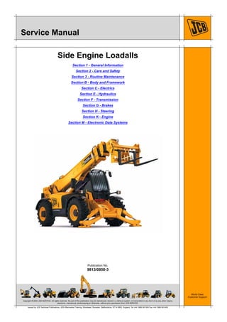
General Information
Care and Safety
Routine Maintenance
Body and Framework
Electrics
Hydraulics
Transmission
Brakes
Steering
Engine
Electronic Data Systems
File Format: PDF
Compatible: All Versions of Windows & Mac
Language: English
Requirements: Adobe PDF Reader
NO waiting, Buy from responsible seller and get INSTANT DOWNLOAD, Without wasting your hard-owned money on uncertainty or surprise! All pages are is great to haveJCB 535-125 HI VIZ TELESCOPIC HANDLER Service Repair Workshop Manual.
Looking for some other Service Repair Manual,please check:
https://www.aservicemanualpdf.com/
Thanks for visiting!
2. Page No.Contents
Section 1 - General Information
1-i 1-i
Applications
Introduction ............................................................................................. 1-1-1
Tables ..................................................................................................... 1-1-2
Use
Introduction ............................................................................................. 1-2-1
Scope ..................................................................................................... 1-2-2
Format .................................................................................................... 1-2-3
Left and Right Sides ............................................................................... 1-2-4
Hydraulic Schematic Codes ................................................................... 1-2-5
Electrical Device Codes .......................................................................... 1-2-6
Machine Identification
Introduction ............................................................................................. 1-3-1
Related Topics ........................................................................................ 1-3-2
Machine Identification Plate .................................................................... 1-3-3
Component Identification Plates ............................................................. 1-3-4
Torque Settings
Introduction ............................................................................................. 1-4-1
Zinc Plated Fasteners and Dacromet Fasteners .................................... 1-4-2
Hydraulic Connections ............................................................................ 1-4-6
`Positional Type' Hydraulic Adaptors .................................................... 1-4-10
Service Tools
Introduction ............................................................................................. 1-5-1
Numerical List ......................................................................................... 1-5-2
Tool Detail Reference ............................................................................. 1-5-5
Rivet Nuts ............................................................................................. 1-5-23
Slide Hammer Kit .................................................................................. 1-5-25
Service Consumables
Introduction ............................................................................................. 1-6-1
Sealing and Retaining Compounds ........................................................ 1-6-2
Fuel
Introduction ............................................................................................. 1-7-1
Related Topics ........................................................................................ 1-7-2
Acceptable and Unacceptable Fuels ...................................................... 1-7-3
Stall Speed Combinations
Introduction ............................................................................................. 1-8-1
Related Topics ........................................................................................ 1-8-2
Specifications ......................................................................................... 1-8-3
3. Section 1-1 - General Information
1-1-1 1-1-19813/0950-2 (1-14-04)
Applications
Introduction
This manual contains topics that relate to some or all JCB Loadall machines in the 5A group. There are several machine
model codes in the family.
Machine Group Model Code Model Name Serial Number range:
5A F 540-170 from 1522578 to TBA
5A L 540-140 TBA
5A N 535-125 Hi Viz from 1522579 to TBA
5A P 535-140 Hi Viz from 1522591 to TBA
Note: This manual is applicable to EN15000 compliant machines only.
Machine variants: There are different machine variants within the same model name. This happens because of market
requirements, or when the machine specification changes after a period of time. Information relating specifically to
different variants of the same model is given in the applications tables and in the Topics throughout the manual where
applicable.
Use the applications tables to see which topics relate to which machine models and variants.
Important: The machine model names are NOT referred to in the topics. You must refer to the applications tables for
the applicable machine models.
K Tables ( T 1-1-2)
K Section 1 - General Information ( T 1-1-2)
K Section 2 - Care and Safety ( T 1-1-3)
K Section 3 - Routine Maintenance ( T 1-1-4)
K Section B - Body and Framework ( T 1-1-5)
K Section C - Electrics ( T 1-1-6)
K Section E - Hydraulics ( T 1-1-7)
K Section F - Transmission ( T 1-1-8)
K Section G - Brakes ( T 1-1-9)
K Section H - Steering ( T 1-1-10)
K Section K - Engine ( T 1-1-11)
K Section M - Electronic Data Systems ( T 1-1-12)
4. Section 1-1 - General Information
Applications
Tables
1-1-2 1-1-29813/0950-2 (1-14-04)
Tables
Section 1 - General Information
Machine models
Topic
Ref
Title Variant 540-170
5AF
540-140
5AL
535-125
HiViz
5AN
535-140
HiViz
5AP
1-2 Use All Machines
1-3 Machine Identification All Machines
1-4 Torque Settings All Machines
1-5 Service Tools All Machines
1-6 Service Consumables All Machines
1-7 Fuel All Machines
1-8 Stall Speed Combinations All Machines
5. Section 1-1 - General Information
Applications
Tables
1-1-3 1-1-39813/0950-2 (1-14-04)
Section 2 - Care and Safety
Machine models
Topic
Ref
Title Variant 540-170
5AF
540-140
5AL
535-125
HiViz
5AN
535-140
HiViz
5AP
2-1 Safety Notices All Machines
2-2 General Procedures All Machines
7. Section 1-1 - General Information
Applications
Tables
1-1-5 1-1-59813/0950-2 (1-14-04)
Section B - Body and Framework
Machine models
Topic
Ref
Title Variant 540-170
5AF
540-140
5AL
535-125
HiViz
5AN
535-140
HiViz
5AP
B1 Fork Carriage
B2 Cab Heating and Ventilation
SYSTEM
B3 Cab Air Conditioning SYSTEM
B4 Longitudinal Load Moment
SYSTEM (S1)
B5 Longitudinal Load Moment
SYSTEM (S2)
B6 Cab
B7 Air Conditioning Condensor -
Cooling Pack Mounted
B8 Air Conditioning Condensor -
Roof Mounted
B9 Cab HV and HVAC Unit
B10 Air Conditioning Binary Switch
B11 Heater Valve
B12 Fuel Tank
B13 Chassis Panels
B14 Boom 3 Stage
4 Stage
B15 LMI Axle Transducer
B16 Stabilisers
B17 Longitudinal Load Moment
Indicator Unit
B18 Longitudinal Load Moment
Control Sensors
8. Section 1-1 - General Information
Applications
Tables
1-1-6 1-1-69813/0950-2 (1-14-04)
Section C - Electrics
Machine models
Topic
Ref
Title Variant 540-170
5AF
540-140
5AL
535-125
HiViz
5AN
535-140
HiViz
5AP
C1 Fuses and Relays
C2 Schematics
C3 Electrical Harness SYSTEM
C4 Battery Charging SYSTEM
C5 Alternator
C6 Battery
9. Section 1-1 - General Information
Applications
Tables
1-1-7 1-1-79813/0950-2 (1-14-04)
Section E - Hydraulics
Machine models
Topic
Ref
Title Variant 540-170
5AF
540-140
5AL
535-125
HiViz
5AN
535-140
HiViz
5AP
E1 Systems and Schematics
E2 Parallel Hydraulic SYSTEM
E3 Parallel Servo Hydraulic SYSTEM
E4 Hydraulic Interlock SYSTEM
E5 Parallel Control Valve - 6 Section
E6 Parallel Control Valve - 5 Section
E7 Parallel Control Valve - 2 Section
E8 Servo Control Valves
E9 Servo Solenoid Diverter Valve Block
E10 Stabiliser Isolation Valve
E11 Sway/Fan Selector Valve
E12 Main Pump 110 l/min
170 l/min
E13 Cooling Fan Motor
E14 Extension Ram
E15 Lift Rams
E16 Tilt Ram
E17 Displacement Ram
E18 Sway Ram
E19 Stabiliser Rams
E20 Ram Maintenance
10. Section 1-1 - General Information
Applications
Tables
1-1-8 1-1-89813/0950-2 (1-14-04)
Section F - Transmission
Machine models
Topic
Ref
Title Variant 540-170
5AF
540-140
5AL
535-125
HiViz
5AN
535-140
HiViz
5AP
F1 CONFIGURATION
F2 Wheels and Tyres
F3 Front Axles SD80 Pivot
sway
SD80 Trunnion
sway
F4 Rear Axles SD80 Pivot
sway
SD80 Trunnion
sway
F5 PS750 Mk IV Gearbox
SYSTEM
F6 PS764 Gearbox SYSTEM
F7 PS750 Mk IV Gearbox
F8 PS760 Gearbox
F9 Bevel Gearbox
F10 Torque Converter
F11 Transmission Oil Cooler -
Air Blast
Intercooled
engines
F12 Transmission Oil Cooler -
Liquid to Liquid
Non
intercooled
engines
F13 Propshafts
F14 Transmission Speed
Sensor (S1)
F15 Transmission Speed
Sensor (S2)
F16 Engine Speed Sensor
F17 Speedometer
11. Section 1-1 - General Information
Applications
Tables
1-1-9 1-1-99813/0950-2 (1-14-04)
Section G - Brakes
Machine models
Topic
Ref
Title Variant 540-170
5AF
540-140
5AL
535-125
HiViz
5AN
535-140
HiViz
5AP
G1 Twin Axle Service Brakes SYSTEM
(S1)
G2 Twin Axle Service Brakes SYSTEM
(S2)
G3 External Park Brake SYSTEM PS750
gearbox
G4 Internal Park Brake SYSTEM PS760
gearbox
G5 Park Brake Calliper PS750
gearbox
G6 Park Brake Disc PS750
gearbox
G7 Park Brake Switch
G8 Servo Exhauster Unit
G9 Servo Unit - Twin Axle Brakes
G10 Master Cylinder
G11 Fluid Reservoir
12. Thank you very much for
your reading. Please Click
Here. Then Get COMPLETE
MANUAL. NO WAITING
NOTE:
If there is no response to
click on the link above,
please download the PDF
document first and then
click on it.
13. Section 1-1 - General Information
Applications
Tables
1-1-10 1-1-109813/0950-2 (1-14-04)
Section H - Steering
Machine models
Topic
Ref
Title Variant 540-170
5AF
540-140
5AL
535-125
HiViz
5AN
535-140
HiViz
5AP
H1 Steering SYSTEM
H2 Manual Steer Mode SYSTEM
H3 Auto Steer Mode SYSTEM
H4 Hydraulic Steering Unit
H5 Priority Valve
H6 Power Track Rods
H7 Steer Rams
H8 Steering Column
H9 Manual Steer Mode Valve
H10 Auto Steer Mode Valve
14. Section 1-1 - General Information
Applications
Tables
1-1-11 1-1-119813/0950-2 (1-14-04)
Section K - Engine
Machine models
Topic
Ref
Title Variant 540-170
5AF
540-140
5AL
535-125
HiViz
5AN
535-140
HiViz
5AP
K1 Stop and Start SYSTEM
(Mechanical F.I. Engines)
K2 Stop and Start SYSTEM
(Electronic F.I. Engines)
K3 Cold Start Heater SYSTEM Mechanical
F.I. Engines
K4 Starter Motor
K5 Cooling Pack - (Non Intercooled)
K6 Cooling Pack - (Intercooled
Mechanical F.I. Engines)
K7 Cooling Pack - (Electronic F.I.
Engines)
K8 Coolant Expansion Tank
K9 Air Filter Vacuum Switch
K10 Throttle Pedal and Cable
K11 Throttle Position Sensor (TPS)
(S1)
Electronic F.I.
engines up to
March 2011
K12 Throttle Position Sensor (TPS)
(S2)
Electronic F.I.
engines from
March 2011
K13 Exhaust Silencer
K14 JCB Dieselmax (Mechanical F.I.
Engines)
K15 JCB Dieselmax (Electronic F.I.
Engines)
15. Section 1-1 - General Information
Applications
Tables
1-1-12 1-1-129813/0950-2 (1-14-04)
Section M - Electronic Data Systems
Machine models
Topic
Ref
Title Variant 540-170
5AF
540-140
5AL
535-125
HiViz
5AN
535-140
HiViz
5AP
M1 CANbus SYSTEM
M2 Loadall Monitoring SYSTEM
M3 Fault Code SYSTEM
M4 Servicemaster SYSTEM
M5 Servicemaster Tools
M6 Electronic Control Unit Theory
M7 Pulse Width Modulation Theory