SlideShare a Scribd company logo
1 of 18
Download to read offline
SERVICE MANUAL SM63005
355 / 365 TANDEM ROLLER
355K / 365K COMBINATION ROLLER
455 / 465 TANDEM ROLLER
455K / 465K COMBINATION ROLLER
January 2002
1
SECTION ONE
GENERAL INFORMATION
MACHINE DESCRIPTION................................................................................. 1 - 3
SERIAL NUMBERS....................................................................................... 1 - 4
GENERAL SAFETY........................................................................................... 1 - 6
SPARK ARRESTER...................................................................................... 1 - 6
PERSONAL SAFETY .................................................................................... 1 - 7
OPERATING SAFETY .................................................................................. 1 - 8
MAINTENANCE SAFETY................................................................................ 1 - 11
GENERAL INFORMATION.............................................................................. 1 - 14
CLEANING .................................................................................................. 1 - 14
INSPECTION............................................................................................... 1 - 14
BEARINGS .................................................................................................. 1 - 14
NEEDLE BEARINGS................................................................................... 1 - 14
GEARS........................................................................................................ 1 - 14
OIL SEALS, O-RINGS, & GASKETS .......................................................... 1 - 14
SHAFTS ...................................................................................................... 1 - 15
SERVICE PARTS........................................................................................ 1 - 15
LUBRICATION ............................................................................................ 1 - 15
STANDARD TORQUE DATA .......................................................................... 1 - 15
METRIC/USA CONVERSIONS ....................................................................... 1 - 17
MACHINE SPECIFICATIONS ......................................................................... 1 - 18
355/365 SPECIFICATIONS......................................................................... 1 - 18
ENGINE DATA ............................................................................................ 1 - 19
OPERATING DATA..................................................................................... 1 - 19
455/465 SPECIFICATIONS......................................................................... 1 - 20
ENGINE DATA ............................................................................................ 1 - 21
OPERATING DATA..................................................................................... 1 - 21
FLUID CAPACITY............................................................................................ 1 - 22
PNEUMATIC TIRE PRESSURE...................................................................... 1 - 22
DIESEL FUEL SPECIFICATION ..................................................................... 1 - 23
ENGINE OIL SPECIFICATION........................................................................ 1 - 24
SECTION TWO
ENGINE R&I
ENGINE COOLING SYSTEM............................................................................ 2 - 2
ENGINE EXHAUST SYSTEM ........................................................................... 2 - 3
ENGINE INTAKE SYSTEM ............................................................................... 2 - 4
ENGINE FUEL SYSTEM ................................................................................... 2 - 5
HYDRAULIC PUMP CONTROLS...................................................................... 2 - 6
ENGINE MOUNTS............................................................................................. 2 - 7
ENGINE REMOVAL........................................................................................... 2 - 8
ENGINE OVERHAUL ........................................................................................ 2 - 9
KUBOTA ENGINE WARRANTY........................................................................ 2 - 9
2
ENGINE INSTALLATION ................................................................................ 2 - 12
SECTION THREE
ELECTRICAL CIRCUITS
INSTRUMENT PANEL ...................................................................................... 3 - 2
Instrument Panel, Single Amplitude .............................................................. 3 - 2
Instrument Panel, Two Amplitude ................................................................. 3 - 4
Instrument Panel, “K” Model ......................................................................... 3 - 6
Combination Indicator ................................................................................... 3 - 8
Instrument Panel, Right Side ........................................................................ 3 - 9
OPERATOR’S CONSOLE............................................................................... 3 - 10
ELECTRICAL INFORMATION ........................................................................ 3 - 11
Fuses .......................................................................................................... 3 - 12
Relays ......................................................................................................... 3 - 13
UNDERSTANDING ELECTRICAL SCHEMATICS ........................................ 3 - 15
UNDERSTANDING RELAYS.......................................................................... 3 - 18
VIBROMAX RELAYS.................................................................................. 3 - 19
EMERGENCY STOP CIRCUIT....................................................................... 3 - 21
STARTER/ CHARGING CIRCUIT................................................................... 3 - 23
UNDERSTANDING BATTERIES .................................................................... 3 - 23
BATTERY DIAGNOSTICS.......................................................................... 3 - 24
UNDERSTANDING ALTERNATORS ......................................................... 3 - 25
CHARGING SYSTEM DIAGNOSTICS ....................................................... 3 - 26
VOLTAGE CHECKS AT ALTERNATOR ................................................... 3 - 27
SYSTEM LEAKAGE.................................................................................... 3 - 27
CIRCUIT WIRING TEST ............................................................................. 3 - 27
MEASURING ALTERNATOR OUTPUT ..................................................... 3 - 28
UNDERSTANDING STARTERS................................................................. 3 - 28
STARTER SOLENOID................................................................................ 3 - 29
STARTER SYSTEM DIAGNOSTICS .............................................................. 3 - 29
SOLENOID CIRCUIT TEST........................................................................ 3 - 29
STARTER CIRCUIT WIRING TEST ........................................................... 3 - 30
STARTER MOTOR TEST........................................................................... 3 - 31
NEUTRAL SWITCH CIRCUIT......................................................................... 3 - 33
NEUTRAL SWITCH CIRCUIT......................................................................... 3 - 35
INSTRUMENTATION PANEL ......................................................................... 3 - 37
PARKING BRAKE CIRCUIT............................................................................ 3 - 39
VIBRATION CONTROL CIRCUIT (one amplitude)......................................... 3 - 39
VIBRATION CONTROL CIRCUIT (two amplitude) ......................................... 3 - 41
SPRINKLER CIRCUIT..................................................................................... 3 - 43
LIGHTING CIRCUIT........................................................................................ 3 - 45
HAZARD/ DIRECTIONAL CIRCUIT................................................................ 3 - 45
BACK-UP ALARM ........................................................................................... 3 - 46
WIRE HARNESS LAYOUT ............................................................................. 3 - 47
WIRE HARNESS 7140/81115......................................................................... 3 - 48
3
WIRE CHART 7140/81115 .............................................................................. 3 - 50
WIRE HARNESS 7140/81255 ......................................................................... 3 - 52
WIRE CHART 7140/81255 .............................................................................. 3 - 54
WIRE HARNESS 7140/82115 ......................................................................... 3 - 57
WIRE CHART 7140/82115 .............................................................................. 3 - 60
WIRE HARNESS 7140/82255 ......................................................................... 3 - 62
WIRE CHART 7140/82255 .............................................................................. 3 - 64
ELECTRICAL SCHEMATICS .......................................................................... 3 - 69
SECTION FOUR
HYDRAULIC SYSTEMS
PROPULSION DRAWINGS............................................................................... 4 - 2
PROPULSION SYSTEM.................................................................................... 4 - 5
PROPULSION SYSTEM DIAGNOSTICS ..................................................... 4 - 5
INTERNAL LEAKAGE ................................................................................... 4 - 5
PUMP SERVO CONTROL ............................................................................ 4 - 6
VIBRATION DRAWINGS (one amplitude)....................................................... 4 - 10
VIBRATION SYSTEM (one amplitude)............................................................ 4 - 13
VIBRATION DRAWINGS (two amplitude) ....................................................... 4 - 16
VIBRATION SYSTEM (two amplitude) ............................................................ 4 - 19
VIBRATION SYSTEM DIAGNOSTICS........................................................ 4 - 22
VIBRATION FREQUENCY.......................................................................... 4 - 22
STEERING DRAWINGS (without offset) ......................................................... 4 - 23
STEERING SYSTEM (without offset) .............................................................. 4 - 26
STEERING SYSTEM DIAGNOSTICS......................................................... 4 - 26
STEERING DRAWINGS (with offset) .............................................................. 4 - 27
STEERING SYSTEM (with offset) ................................................................... 4 - 29
BRAKE SYSTEM DRAWINGS ........................................................................ 4 - 30
PARKING BRAKES SYSTEM ......................................................................... 4 - 35
PARKING BRAKE DIAGNOSTICS ............................................................. 4 - 35
HYDRAULIC TEST PORTS............................................................................. 4 - 36
COOLER LINES .............................................................................................. 4 - 49
SUCTION LINES ............................................................................................. 4 - 53
HYDRAULIC FILTERS .................................................................................... 4 - 56
HYDRAULIC COMPONENTS ......................................................................... 4 - 57
HYDRAULIC SCHEMATICS............................................................................ 4 - 58
HYDRAULIC COMPONENTS
POCLAIN MC05 PROPULSION MOTOR........................................................ 4 - 66
SAUER/SUNDSTRAND SERIES 42 PROPULSION PUMP ........................... 4 - 69
4
SECTION FIVE
POWER TRAIN
DRUM CROSS-SECTION................................................................................. 5 - 6
DRUM REMOVAL ........................................................................................... 5 - 13
DRIVE MOTOR REMOVAL............................................................................. 5 - 13
DRIVE MOTOR REPAIR................................................................................. 5 - 15
DRIVE MOTOR INSTALLATION..................................................................... 5 - 15
DRUM DRIVE BEARING REMOVAL.............................................................. 5 - 15
DRUM BEARING INSTALLATION.................................................................. 5 - 17
DRUM INSTALLATION ................................................................................... 5 - 17
PNEUMATIC TIRE DRIVE .............................................................................. 5 - 18
SECTION SIX
PARKING BRAKE SYSTEM
PARK BRAKE TESTING................................................................................... 6 - 7
BRAKE RELEASE FOR TOWING .................................................................... 6 - 7
TOWING PROCEDURE ............................................................................... 6 - 8
BRAKE REPAIRS............................................................................................ 6 - 10
BRAKE DISASSEMBLY.............................................................................. 6 - 10
BRAKE ASSEMBLY.................................................................................... 6 - 10
SECTION SEVEN
VIBRATORY SYSTEM
VIBRATION SHAFT (two amplitude)................................................................. 7 - 5
DRUM REMOVAL ............................................................................................. 7 - 7
VIBRATION SHAFT REMOVAL........................................................................ 7 - 7
LEFT VIB. BEARING REMOVAL ...................................................................... 7 - 9
LEFT BEARING INSTALLATION...................................................................... 7 - 9
RIGHT BEARING INSTALLATION.................................................................. 7 - 11
DRUM INSTALLATION ................................................................................... 7 - 11
SECTION EIGHT
STEERING SYSTEM
HORIZONTAL PIVOT DISASSEMBLY......................................................... 8 - 7
STEERING PIVOT DISASSEMBLY.............................................................. 8 - 7
5
SECTION NINE
CHASSIS
ROLL-OVER PROTECTION STRUCTURE (ROPS)......................................... 9 - 3
ROPS maintenance....................................................................................... 9 - 3
ROPS damage .............................................................................................. 9 - 3
Tightening torques......................................................................................... 9 - 4
SECTION TEN
ATTACHMENTS
FRONT HARNESS 7140/90106 ...................................................................... 10 - 2
REAR HARNESS 7140/90111......................................................................... 10 - 2
8364/01150 WORKLIGHT CONNECTOR....................................................... 10 - 2
INSTALLATION OF 87140/90100 WORK LIGHT KIT..................................... 10 - 2
INSTALLATION OF 87140/90150 ROAD LIGHT KIT...................................... 10 - 3
FUSE LAYOUT................................................................................................ 10 - 7
RELAY LAYOUT.............................................................................................. 10 - 8
SPRINKLER SYSTEM..................................................................................... 10 - 9
1 - 1
SECTION ONE
GENERAL INFORMATION
SM63005 - SECTION ONE GENERAL INFORMATION
1 - 2
Built with serviceability in mind.
SM63005 - SECTION ONE GENERAL INFORMATION
1 - 3
MACHINE DESCRIPTION
The Vibromax Model 355/365 is a 3.5 metric
ton tandem drum roller with articulated
steering, hydrostatic propulsion and a
hydrostatic vibratory system. The Model 455/
465 is a larger 4.5 metric ton tandem drum
roller. Both the 3.5 and 4.5 ton machines offer
a “K” model option. The “K” model is a
combination machine offering a steel front
drum and pneumatic tires in place of the rear
drum.
Power is provided by a 134.4 cubic inch (2197
cc) Kubota, four cylinder diesel engine, Model
V2203-E, rated at 46.6 hp SAE net (34.3 kW)
at 2600 RPM.
The operator’s platform was designed using
modern techniques to assure good visibility
and operator comfort. The operator’s seat box
can be tilted forward to gain easy access to the
machine’s hydraulic pumps and valves.
Both tandem roller models operate at a
vibration frequency of 3300 vibrations per
minute (55 Hz). Vibratory operation is available
for either the front drum or both drums. A two
frequency/two amplitude option is available for
both the 3.5 and 4.5 metric ton machines. The
second vibration frequency is 3000 vpm. (50
Hz). On the “K” model only the front drum will
vibrate.
The hydrostatic drive system allows for
infinitely variable ground speed. All machines
are equipped with a two speed arrangement
which provides greater control in the 0 to 4 mph
range. The hydrostatic drive system consists of
a piston pump and front and rear drum drive
motors. Hydraulic release, spring applied
parking brakes are incorporated into the design
of the drum motors. On the “K” model two
smaller hydraulic motors are used to drive the
right and left side pneumatic tires. Brakes are
also incorporated into “K” model drive motors.
As a factory option, these machines offer an
articulation offset of five inches (127 mm) to the
left or right of center position. This feature is
most useful when compacting asphalt on tight
turns.
These machines are equipped with an
intermittent sprinkler system for use in asphalt
applications. The water tanks are made of a
rust proof synthetic material. The system is a
pressure spray type with sprinkler tubes fitted
with nozzles. The system controls are
designed to allow variable off times in the
automatic mode to minimize water usage. The
pneumatic “K” model offers separate sprinkler
systems for the front and rear of the machine to
allow the use of special soap solutions on the
rear tires. Both systems have variable controls.
Each drum is equipped with front and rear
scrapers. The scrapers are spring loaded
against the drum and can easily be moved
away from the drum for soil and gravel
compaction jobs. Scrapers are also available
on the “K” model. A cocoa mat option is also
available.
As sold in the United States the machines are
fitted with a Roll Over Protective Structure
(ROPS). A seat belt is provided as part of the
ROPS system.
As sold in the United States the machines are
also fitted with a standard Back-up alarm
system and an emergency stop system.
All models include a centralized testing station
for quick and easy diagnostics for the various
hydraulic systems.
Road lights, work lights, FOPS, and a sun roof
are four standard options. Other additional
equipment such as beacon lights, slow moving
machine signs, etc., are available as special
order items. If you have special needs please
contact your dealer.
SM63005 - SECTION ONE GENERAL INFORMATION
1 - 4
SERIAL NUMBERS
1 Model / Serial Number
2 Front Drum Drive Motor S/N
3 Rear Drum Drive Motor S/N
4 Steering Unit S/N
5 Front Vibratory Motor S/N
6 Rear Vibratory Motor S/N
7 Hydraulic Pumps S/N
8 Engine S/N
SM63005 - SECTION ONE GENERAL INFORMATION
1 - 5
IDENTIFYING MACHINE COMPONENTS
1 Articulation joint 11 Spring loaded brake
2 Smooth drum 12 Water tank
3 Lifting/tie-down eye 13 Fuel tank
4 Operator’s stand 14 Air filter canister
5 Battery 15 Water - oil cooler
6 Hydraulic tank 16 Roll over protection
7 Engine 17 Vibration motor
8 Drum drive motor 18 Steering cylinder
9 Rubber buffer 19 Hydraulic pumps
10 Scraper 20 Sun roof
SM63005 - SECTION ONE GENERAL INFORMATION
1 - 6
GENERAL SAFETY
The information in this manual does not replace any safety rules and laws used in your area. Before
operating this machine, learn the rules and laws for your area and make sure your machine has the
correct equipment according to these rules and regulations. Before starting the engine study the
operator’s manual.
• Know the location and function of all machine controls.
• Clear the area of other persons before you start the engine.
• Check all controls in a safe area before you operate the machine.
• Understand the limits of the machine.
• Do not try to do too much too fast.
• Keep the machine under control at all times.
The following decal is located on the right side of the water tank. Check the decal daily. Clean or
replace as needed.
SPARK ARRESTER
NOTE: Rules or laws in some areas may require that this machine be equipped with a
spark arrester or spark arrester muffler. Check the rules or laws in your area.
Thank you very much for
your reading. Please Click
Here. Then Get COMPLETE
MANUAL. NO WAITING
NOTE:
If there is no response to
click on the link above,
please download the PDF
document first and then
click on it.
SM63005 - SECTION ONE GENERAL INFORMATION
1 - 7
PERSONAL SAFETY
Loose clothing and jewelry can cause an accident. Do not wear loose clothing or jewelry
that can catch on controls, etc. Do wear safety shoes, hard hat, heavy gloves, etc. when
required for your protection.
Foreign materials and loose objects on the steps, hand rails, and in the operators com-
partment can cause accidents and injury. Keep the steps, hand rails, and operator’s
compartment clear at all times.
Know and understand the arrangements for movement of trucks, machines, and per-
sons on your job site. Understand and follow the instructions of flagmen, road signs, or
signals.
Check machine controls for proper operation prior to starting the machine.
A fire can cause injury or death. Always have a fire extinguisher on the job site near the
machine. Make sure the fire extinguisher is serviced according to the manufacturer’s
instructions.
Holes, obstructions, debris, and other work area hazards can cause injury or death.
Always walk-around and look for these and other hazards before you operate your
machine in a new work area.
Lack of, or incomplete, machine inspection and maintenance can cause accidents.
Always follow the instructions in this manual for machine inspection and maintenance.
Always use the seat belt when operating the machine. Make sure the buckle is fully
secured.
SM63005 - SECTION ONE GENERAL INFORMATION
1 - 8
The following decal is located on the upper rear side of the steering column. Check the decal daily.
Clean or replace as needed.
Always wear the proper ear protection when operating this machine. Permanent hearing
loss can result from extended exposure to loud noises.
The following decal is located on the instrument panel to the right side of the main gauge cluster.
Check the decal daily. Clean or replace as needed.
OPERATING SAFETY
Dust, smoke, fog, etc. can decrease your vision and cause an accident. Always stop or
slow the machine until you can clearly see your work area and the surrounding traffic.
SM63005 - SECTION ONE GENERAL INFORMATION
1 - 9
Operate the controls from the operator’s seat only, and keep your hands on the controls
during operation.
The following decal is located on the left side of the water tank. Check the decal daily. Clean or
replace as needed.
Do not permit other people to ride on the machine as passengers.
Sparks from the electrical system or engine exhaust can cause a fire or explosion.
Before you operate this machine in an area with flammable dust or vapors, use good
ventilation to remove the flammable dust or vapors.
Engine exhaust fumes can cause injury or death. If you operate this machine in an
enclosed area, use good ventilation to replace the exhaust fumes with fresh air.
The vibrations from this machine can cause the walls of a trench or high bank to col-
lapse. Make sure the walls of the trench or bank are braced. If you do not follow these
instructions, you can cause personal injury or death to persons working in these areas.
This machine uses an articulating joint. Keep all persons clear of this pinch area when
the engine is running. Machine movement can cause personal injury.
The following decal is located on each side of the machine’s and rear frames floor panel in the
articulation joint area. Check the decals daily. Clean or replace as needed.
SM63005 - SECTION ONE GENERAL INFORMATION
1 - 10
The following decal is also located on both sides of the rear frame in the area of the articulation joint
and symbolizes the danger of the pinch point. Check the decal daily. Clean or replace as needed.
The following decal is located on the right side of the water tank. Check the decal daily. Clean or
replace as needed
SM63005 - SECTION ONE GENERAL INFORMATION
1 - 11
A machine out of control can cause injury or death. You must make a judgement if
weather and earth conditions will permit safe operation on a hill, ramp, or rough ground.
Adjust machine operation accordingly.
Operating this machine too close to High Voltage electrical lines can cause injury or
death. Follow the guide lines listed below.
NOTE: IF THE CLEARANCES IN THE SPECIFICATIONS BELOW ARE LESS THAN THE
CLEARANCES GIVEN IN THE RULES AND LAWS OF YOUR AREA,YOU MUST FOLLOW
THE RULES AND LAWS OF YOUR AREA!
MAINTENANCE SAFETY
The following decal is located on the left side of the front roller frame. Check the decal daily. Clean or
replace as needed
Table 1: Electrical Safety Rules
Cable Voltage
Minimum Clearance
From Cable When
Machine is Working
Minimum Clearance
From Cable When
Transporting Machine
50,000 volts or less 10 feet (3 meters) 4 feet (1.2 meters)
50,000 volts to
345,000 volts
10 feet (3m) plus 1/2
inch (13mm) for
every 1000 volts
over 50,000 volts
10 feet (3 meters)
345,000 volts to
750,000 volts
10 feet (3m) plus 1/2
inch (13mm) for
every 1000 volts
over 50,000 volts
16 feet (5 meters)

More Related Content

What's hot

New holland ts125 a tractor service repair manual
New holland ts125 a tractor service repair manualNew holland ts125 a tractor service repair manual
New holland ts125 a tractor service repair manualujdjjkskkmdme
 
Cummins onan c275 d6 generator set with power command 1302 controller service...
Cummins onan c275 d6 generator set with power command 1302 controller service...Cummins onan c275 d6 generator set with power command 1302 controller service...
Cummins onan c275 d6 generator set with power command 1302 controller service...jfjskeksemmmd
 
Cummins onan c275 d5 generator set with power command 1302 controller service...
Cummins onan c275 d5 generator set with power command 1302 controller service...Cummins onan c275 d5 generator set with power command 1302 controller service...
Cummins onan c275 d5 generator set with power command 1302 controller service...fksefkskemm
 
Cummins Onan C330 D5 Generator Set with PowerCommand 1302 Controller Service ...
Cummins Onan C330 D5 Generator Set with PowerCommand 1302 Controller Service ...Cummins Onan C330 D5 Generator Set with PowerCommand 1302 Controller Service ...
Cummins Onan C330 D5 Generator Set with PowerCommand 1302 Controller Service ...fujdfjjskekdmem
 
Cummins onan c300 d6 generator set with power command 1302 controller service...
Cummins onan c300 d6 generator set with power command 1302 controller service...Cummins onan c300 d6 generator set with power command 1302 controller service...
Cummins onan c300 d6 generator set with power command 1302 controller service...jfksekfmsme
 
Cummins onan c300 d5 generator set with power command 1302 controller service...
Cummins onan c300 d5 generator set with power command 1302 controller service...Cummins onan c300 d5 generator set with power command 1302 controller service...
Cummins onan c300 d5 generator set with power command 1302 controller service...fjsexswkfkmsem
 

What's hot (6)

New holland ts125 a tractor service repair manual
New holland ts125 a tractor service repair manualNew holland ts125 a tractor service repair manual
New holland ts125 a tractor service repair manual
 
Cummins onan c275 d6 generator set with power command 1302 controller service...
Cummins onan c275 d6 generator set with power command 1302 controller service...Cummins onan c275 d6 generator set with power command 1302 controller service...
Cummins onan c275 d6 generator set with power command 1302 controller service...
 
Cummins onan c275 d5 generator set with power command 1302 controller service...
Cummins onan c275 d5 generator set with power command 1302 controller service...Cummins onan c275 d5 generator set with power command 1302 controller service...
Cummins onan c275 d5 generator set with power command 1302 controller service...
 
Cummins Onan C330 D5 Generator Set with PowerCommand 1302 Controller Service ...
Cummins Onan C330 D5 Generator Set with PowerCommand 1302 Controller Service ...Cummins Onan C330 D5 Generator Set with PowerCommand 1302 Controller Service ...
Cummins Onan C330 D5 Generator Set with PowerCommand 1302 Controller Service ...
 
Cummins onan c300 d6 generator set with power command 1302 controller service...
Cummins onan c300 d6 generator set with power command 1302 controller service...Cummins onan c300 d6 generator set with power command 1302 controller service...
Cummins onan c300 d6 generator set with power command 1302 controller service...
 
Cummins onan c300 d5 generator set with power command 1302 controller service...
Cummins onan c300 d5 generator set with power command 1302 controller service...Cummins onan c300 d5 generator set with power command 1302 controller service...
Cummins onan c300 d5 generator set with power command 1302 controller service...
 

Similar to Jcb 355 k combination roller service repair manual

JCB VIBROMAX 255 265 TANDEM ROLLER Service Repair Manual Instant Download.pdf
JCB VIBROMAX 255 265 TANDEM ROLLER Service Repair Manual Instant Download.pdfJCB VIBROMAX 255 265 TANDEM ROLLER Service Repair Manual Instant Download.pdf
JCB VIBROMAX 255 265 TANDEM ROLLER Service Repair Manual Instant Download.pdff8iseoddm9i
 
JCB VIBROMAX 255 265 TANDEM ROLLER Service Repair Manual Instant Download.pdf
JCB VIBROMAX 255 265 TANDEM ROLLER Service Repair Manual Instant Download.pdfJCB VIBROMAX 255 265 TANDEM ROLLER Service Repair Manual Instant Download.pdf
JCB VIBROMAX 255 265 TANDEM ROLLER Service Repair Manual Instant Download.pdfifkksem9didok
 
JCB VIBROMAX 265 TANDEM ROLLER Service Repair Manual
JCB VIBROMAX 265 TANDEM ROLLER Service Repair ManualJCB VIBROMAX 265 TANDEM ROLLER Service Repair Manual
JCB VIBROMAX 265 TANDEM ROLLER Service Repair Manualuekmmmd
 
JCB VIBROMAX 255 265 TANDEM ROLLER Service Repair Manual Instant Download.pdf
JCB VIBROMAX 255 265 TANDEM ROLLER Service Repair Manual Instant Download.pdfJCB VIBROMAX 255 265 TANDEM ROLLER Service Repair Manual Instant Download.pdf
JCB VIBROMAX 255 265 TANDEM ROLLER Service Repair Manual Instant Download.pdftan0033118
 
JCB VIBROMAX 255 265 TANDEM ROLLER Service Repair Manual Instant Download.pdf
JCB VIBROMAX 255 265 TANDEM ROLLER Service Repair Manual Instant Download.pdfJCB VIBROMAX 255 265 TANDEM ROLLER Service Repair Manual Instant Download.pdf
JCB VIBROMAX 255 265 TANDEM ROLLER Service Repair Manual Instant Download.pdfzao908wangsa
 
JCB VIBROMAX 255 265 TANDEM ROLLER Service Repair Manual Instant Download.pdf
JCB VIBROMAX 255 265 TANDEM ROLLER Service Repair Manual Instant Download.pdfJCB VIBROMAX 255 265 TANDEM ROLLER Service Repair Manual Instant Download.pdf
JCB VIBROMAX 255 265 TANDEM ROLLER Service Repair Manual Instant Download.pdfid9sodkdkmdm
 
Bobcat t35130 s telescopic handler service repair manual (sn b3kv11001 and ab...
Bobcat t35130 s telescopic handler service repair manual (sn b3kv11001 and ab...Bobcat t35130 s telescopic handler service repair manual (sn b3kv11001 and ab...
Bobcat t35130 s telescopic handler service repair manual (sn b3kv11001 and ab...fjskekfsemmwe
 
Jcb vibromax 405 single drum roller service repair manual
Jcb vibromax 405 single drum roller service repair manualJcb vibromax 405 single drum roller service repair manual
Jcb vibromax 405 single drum roller service repair manualfjjskeknjufksemm
 

Similar to Jcb 355 k combination roller service repair manual (8)

JCB VIBROMAX 255 265 TANDEM ROLLER Service Repair Manual Instant Download.pdf
JCB VIBROMAX 255 265 TANDEM ROLLER Service Repair Manual Instant Download.pdfJCB VIBROMAX 255 265 TANDEM ROLLER Service Repair Manual Instant Download.pdf
JCB VIBROMAX 255 265 TANDEM ROLLER Service Repair Manual Instant Download.pdf
 
JCB VIBROMAX 255 265 TANDEM ROLLER Service Repair Manual Instant Download.pdf
JCB VIBROMAX 255 265 TANDEM ROLLER Service Repair Manual Instant Download.pdfJCB VIBROMAX 255 265 TANDEM ROLLER Service Repair Manual Instant Download.pdf
JCB VIBROMAX 255 265 TANDEM ROLLER Service Repair Manual Instant Download.pdf
 
JCB VIBROMAX 265 TANDEM ROLLER Service Repair Manual
JCB VIBROMAX 265 TANDEM ROLLER Service Repair ManualJCB VIBROMAX 265 TANDEM ROLLER Service Repair Manual
JCB VIBROMAX 265 TANDEM ROLLER Service Repair Manual
 
JCB VIBROMAX 255 265 TANDEM ROLLER Service Repair Manual Instant Download.pdf
JCB VIBROMAX 255 265 TANDEM ROLLER Service Repair Manual Instant Download.pdfJCB VIBROMAX 255 265 TANDEM ROLLER Service Repair Manual Instant Download.pdf
JCB VIBROMAX 255 265 TANDEM ROLLER Service Repair Manual Instant Download.pdf
 
JCB VIBROMAX 255 265 TANDEM ROLLER Service Repair Manual Instant Download.pdf
JCB VIBROMAX 255 265 TANDEM ROLLER Service Repair Manual Instant Download.pdfJCB VIBROMAX 255 265 TANDEM ROLLER Service Repair Manual Instant Download.pdf
JCB VIBROMAX 255 265 TANDEM ROLLER Service Repair Manual Instant Download.pdf
 
Bobcat t35130 s telescopic handler service repair manual (sn b3kv11001 and ab...
Bobcat t35130 s telescopic handler service repair manual (sn b3kv11001 and ab...Bobcat t35130 s telescopic handler service repair manual (sn b3kv11001 and ab...
Bobcat t35130 s telescopic handler service repair manual (sn b3kv11001 and ab...
 
Jcb vibromax 405 single drum roller service repair manual
Jcb vibromax 405 single drum roller service repair manualJcb vibromax 405 single drum roller service repair manual
Jcb vibromax 405 single drum roller service repair manual
 

More from fujsekksmem

Kawasaki 70 z7 wheel loader service repair manual (serial no. 70c6 5001 and up)
Kawasaki 70 z7 wheel loader service repair manual (serial no. 70c6 5001 and up)Kawasaki 70 z7 wheel loader service repair manual (serial no. 70c6 5001 and up)
Kawasaki 70 z7 wheel loader service repair manual (serial no. 70c6 5001 and up)fujsekksmem
 
Kawasaki 70 z6 wheel loader service repair manual (serial no. 70c7 0101 and up)
Kawasaki 70 z6 wheel loader service repair manual (serial no. 70c7 0101 and up)Kawasaki 70 z6 wheel loader service repair manual (serial no. 70c7 0101 and up)
Kawasaki 70 z6 wheel loader service repair manual (serial no. 70c7 0101 and up)fujsekksmem
 
Kawasaki 70 z6 wheel loader equipment components parts catalogue manual (seri...
Kawasaki 70 z6 wheel loader equipment components parts catalogue manual (seri...Kawasaki 70 z6 wheel loader equipment components parts catalogue manual (seri...
Kawasaki 70 z6 wheel loader equipment components parts catalogue manual (seri...fujsekksmem
 
Kawasaki 70 z6 80z6 wheel loader operator manual (serial no. 80c7 0101 and up)
Kawasaki 70 z6  80z6 wheel loader operator manual (serial no. 80c7 0101 and up)Kawasaki 70 z6  80z6 wheel loader operator manual (serial no. 80c7 0101 and up)
Kawasaki 70 z6 80z6 wheel loader operator manual (serial no. 80c7 0101 and up)fujsekksmem
 
Kawasaki 70 z6 80z6 wheel loader operator manual (serial no. 70c7 0101 and up)
Kawasaki 70 z6  80z6 wheel loader operator manual (serial no. 70c7 0101 and up)Kawasaki 70 z6  80z6 wheel loader operator manual (serial no. 70c7 0101 and up)
Kawasaki 70 z6 80z6 wheel loader operator manual (serial no. 70c7 0101 and up)fujsekksmem
 
Kawasaki 70 tm7 wheel loader service repair manual (serial no. 70c6 5001 and up)
Kawasaki 70 tm7 wheel loader service repair manual (serial no. 70c6 5001 and up)Kawasaki 70 tm7 wheel loader service repair manual (serial no. 70c6 5001 and up)
Kawasaki 70 tm7 wheel loader service repair manual (serial no. 70c6 5001 and up)fujsekksmem
 
Kawasaki 67 z7b wheel loader service repair manual (serial no. 65c5 5001 and up)
Kawasaki 67 z7b wheel loader service repair manual (serial no. 65c5 5001 and up)Kawasaki 67 z7b wheel loader service repair manual (serial no. 65c5 5001 and up)
Kawasaki 67 z7b wheel loader service repair manual (serial no. 65c5 5001 and up)fujsekksmem
 
Kawasaki 67 z7b wheel loader parts catalogue manual (serial no. 65c5 5001 and...
Kawasaki 67 z7b wheel loader parts catalogue manual (serial no. 65c5 5001 and...Kawasaki 67 z7b wheel loader parts catalogue manual (serial no. 65c5 5001 and...
Kawasaki 67 z7b wheel loader parts catalogue manual (serial no. 65c5 5001 and...fujsekksmem
 
Kawasaki 67 z7b wheel loader operation and maintenance manual (serial no. 65c...
Kawasaki 67 z7b wheel loader operation and maintenance manual (serial no. 65c...Kawasaki 67 z7b wheel loader operation and maintenance manual (serial no. 65c...
Kawasaki 67 z7b wheel loader operation and maintenance manual (serial no. 65c...fujsekksmem
 
Kawasaki 67 z7 67tm7 wheel loader service repair manual (65j5 8001 and up)
Kawasaki 67 z7  67tm7 wheel loader service repair manual (65j5 8001 and up)Kawasaki 67 z7  67tm7 wheel loader service repair manual (65j5 8001 and up)
Kawasaki 67 z7 67tm7 wheel loader service repair manual (65j5 8001 and up)fujsekksmem
 
Kawasaki 67 z7 67tm7 wheel loader service repair manual (65j5 5001 and up)
Kawasaki 67 z7  67tm7 wheel loader service repair manual (65j5 5001 and up)Kawasaki 67 z7  67tm7 wheel loader service repair manual (65j5 5001 and up)
Kawasaki 67 z7 67tm7 wheel loader service repair manual (65j5 5001 and up)fujsekksmem
 
Kawasaki 67 tm7b wheel loader operation and maintenance manual (serial no. 65...
Kawasaki 67 tm7b wheel loader operation and maintenance manual (serial no. 65...Kawasaki 67 tm7b wheel loader operation and maintenance manual (serial no. 65...
Kawasaki 67 tm7b wheel loader operation and maintenance manual (serial no. 65...fujsekksmem
 
Kawasaki 62 z7 67z7 67tm7 wheel loader service repair manual (65j5 5001 and...
Kawasaki 62 z7  67z7  67tm7 wheel loader service repair manual (65j5 5001 and...Kawasaki 62 z7  67z7  67tm7 wheel loader service repair manual (65j5 5001 and...
Kawasaki 62 z7 67z7 67tm7 wheel loader service repair manual (65j5 5001 and...fujsekksmem
 
Kawasaki 62 z7 67z7 67tm7 wheel loader service repair manual (62j1 5001 and...
Kawasaki 62 z7  67z7  67tm7 wheel loader service repair manual (62j1 5001 and...Kawasaki 62 z7  67z7  67tm7 wheel loader service repair manual (62j1 5001 and...
Kawasaki 62 z7 67z7 67tm7 wheel loader service repair manual (62j1 5001 and...fujsekksmem
 
Kawasaki 60 z7 wheel loader parts catalogue manual (serial no. 60d1 5001 and up)
Kawasaki 60 z7 wheel loader parts catalogue manual (serial no. 60d1 5001 and up)Kawasaki 60 z7 wheel loader parts catalogue manual (serial no. 60d1 5001 and up)
Kawasaki 60 z7 wheel loader parts catalogue manual (serial no. 60d1 5001 and up)fujsekksmem
 
Kawasaki 60 z7 wheel loader parts catalogue manual (60d1 8001 and up)
Kawasaki 60 z7 wheel loader parts catalogue manual (60d1 8001 and up)Kawasaki 60 z7 wheel loader parts catalogue manual (60d1 8001 and up)
Kawasaki 60 z7 wheel loader parts catalogue manual (60d1 8001 and up)fujsekksmem
 
Caterpillar cat 325 ln excavator (prefix 9sg) service repair manual (9sg00001...
Caterpillar cat 325 ln excavator (prefix 9sg) service repair manual (9sg00001...Caterpillar cat 325 ln excavator (prefix 9sg) service repair manual (9sg00001...
Caterpillar cat 325 ln excavator (prefix 9sg) service repair manual (9sg00001...fujsekksmem
 
Caterpillar cat 325 ll excavator (prefix 7lm) service repair manual (7lm00001...
Caterpillar cat 325 ll excavator (prefix 7lm) service repair manual (7lm00001...Caterpillar cat 325 ll excavator (prefix 7lm) service repair manual (7lm00001...
Caterpillar cat 325 ll excavator (prefix 7lm) service repair manual (7lm00001...fujsekksmem
 
Caterpillar cat 325 l track type excavator (prefix 8nl) service repair manual...
Caterpillar cat 325 l track type excavator (prefix 8nl) service repair manual...Caterpillar cat 325 l track type excavator (prefix 8nl) service repair manual...
Caterpillar cat 325 l track type excavator (prefix 8nl) service repair manual...fujsekksmem
 
Caterpillar cat 325 l track type excavator (prefix 8jg) service repair manual...
Caterpillar cat 325 l track type excavator (prefix 8jg) service repair manual...Caterpillar cat 325 l track type excavator (prefix 8jg) service repair manual...
Caterpillar cat 325 l track type excavator (prefix 8jg) service repair manual...fujsekksmem
 

More from fujsekksmem (20)

Kawasaki 70 z7 wheel loader service repair manual (serial no. 70c6 5001 and up)
Kawasaki 70 z7 wheel loader service repair manual (serial no. 70c6 5001 and up)Kawasaki 70 z7 wheel loader service repair manual (serial no. 70c6 5001 and up)
Kawasaki 70 z7 wheel loader service repair manual (serial no. 70c6 5001 and up)
 
Kawasaki 70 z6 wheel loader service repair manual (serial no. 70c7 0101 and up)
Kawasaki 70 z6 wheel loader service repair manual (serial no. 70c7 0101 and up)Kawasaki 70 z6 wheel loader service repair manual (serial no. 70c7 0101 and up)
Kawasaki 70 z6 wheel loader service repair manual (serial no. 70c7 0101 and up)
 
Kawasaki 70 z6 wheel loader equipment components parts catalogue manual (seri...
Kawasaki 70 z6 wheel loader equipment components parts catalogue manual (seri...Kawasaki 70 z6 wheel loader equipment components parts catalogue manual (seri...
Kawasaki 70 z6 wheel loader equipment components parts catalogue manual (seri...
 
Kawasaki 70 z6 80z6 wheel loader operator manual (serial no. 80c7 0101 and up)
Kawasaki 70 z6  80z6 wheel loader operator manual (serial no. 80c7 0101 and up)Kawasaki 70 z6  80z6 wheel loader operator manual (serial no. 80c7 0101 and up)
Kawasaki 70 z6 80z6 wheel loader operator manual (serial no. 80c7 0101 and up)
 
Kawasaki 70 z6 80z6 wheel loader operator manual (serial no. 70c7 0101 and up)
Kawasaki 70 z6  80z6 wheel loader operator manual (serial no. 70c7 0101 and up)Kawasaki 70 z6  80z6 wheel loader operator manual (serial no. 70c7 0101 and up)
Kawasaki 70 z6 80z6 wheel loader operator manual (serial no. 70c7 0101 and up)
 
Kawasaki 70 tm7 wheel loader service repair manual (serial no. 70c6 5001 and up)
Kawasaki 70 tm7 wheel loader service repair manual (serial no. 70c6 5001 and up)Kawasaki 70 tm7 wheel loader service repair manual (serial no. 70c6 5001 and up)
Kawasaki 70 tm7 wheel loader service repair manual (serial no. 70c6 5001 and up)
 
Kawasaki 67 z7b wheel loader service repair manual (serial no. 65c5 5001 and up)
Kawasaki 67 z7b wheel loader service repair manual (serial no. 65c5 5001 and up)Kawasaki 67 z7b wheel loader service repair manual (serial no. 65c5 5001 and up)
Kawasaki 67 z7b wheel loader service repair manual (serial no. 65c5 5001 and up)
 
Kawasaki 67 z7b wheel loader parts catalogue manual (serial no. 65c5 5001 and...
Kawasaki 67 z7b wheel loader parts catalogue manual (serial no. 65c5 5001 and...Kawasaki 67 z7b wheel loader parts catalogue manual (serial no. 65c5 5001 and...
Kawasaki 67 z7b wheel loader parts catalogue manual (serial no. 65c5 5001 and...
 
Kawasaki 67 z7b wheel loader operation and maintenance manual (serial no. 65c...
Kawasaki 67 z7b wheel loader operation and maintenance manual (serial no. 65c...Kawasaki 67 z7b wheel loader operation and maintenance manual (serial no. 65c...
Kawasaki 67 z7b wheel loader operation and maintenance manual (serial no. 65c...
 
Kawasaki 67 z7 67tm7 wheel loader service repair manual (65j5 8001 and up)
Kawasaki 67 z7  67tm7 wheel loader service repair manual (65j5 8001 and up)Kawasaki 67 z7  67tm7 wheel loader service repair manual (65j5 8001 and up)
Kawasaki 67 z7 67tm7 wheel loader service repair manual (65j5 8001 and up)
 
Kawasaki 67 z7 67tm7 wheel loader service repair manual (65j5 5001 and up)
Kawasaki 67 z7  67tm7 wheel loader service repair manual (65j5 5001 and up)Kawasaki 67 z7  67tm7 wheel loader service repair manual (65j5 5001 and up)
Kawasaki 67 z7 67tm7 wheel loader service repair manual (65j5 5001 and up)
 
Kawasaki 67 tm7b wheel loader operation and maintenance manual (serial no. 65...
Kawasaki 67 tm7b wheel loader operation and maintenance manual (serial no. 65...Kawasaki 67 tm7b wheel loader operation and maintenance manual (serial no. 65...
Kawasaki 67 tm7b wheel loader operation and maintenance manual (serial no. 65...
 
Kawasaki 62 z7 67z7 67tm7 wheel loader service repair manual (65j5 5001 and...
Kawasaki 62 z7  67z7  67tm7 wheel loader service repair manual (65j5 5001 and...Kawasaki 62 z7  67z7  67tm7 wheel loader service repair manual (65j5 5001 and...
Kawasaki 62 z7 67z7 67tm7 wheel loader service repair manual (65j5 5001 and...
 
Kawasaki 62 z7 67z7 67tm7 wheel loader service repair manual (62j1 5001 and...
Kawasaki 62 z7  67z7  67tm7 wheel loader service repair manual (62j1 5001 and...Kawasaki 62 z7  67z7  67tm7 wheel loader service repair manual (62j1 5001 and...
Kawasaki 62 z7 67z7 67tm7 wheel loader service repair manual (62j1 5001 and...
 
Kawasaki 60 z7 wheel loader parts catalogue manual (serial no. 60d1 5001 and up)
Kawasaki 60 z7 wheel loader parts catalogue manual (serial no. 60d1 5001 and up)Kawasaki 60 z7 wheel loader parts catalogue manual (serial no. 60d1 5001 and up)
Kawasaki 60 z7 wheel loader parts catalogue manual (serial no. 60d1 5001 and up)
 
Kawasaki 60 z7 wheel loader parts catalogue manual (60d1 8001 and up)
Kawasaki 60 z7 wheel loader parts catalogue manual (60d1 8001 and up)Kawasaki 60 z7 wheel loader parts catalogue manual (60d1 8001 and up)
Kawasaki 60 z7 wheel loader parts catalogue manual (60d1 8001 and up)
 
Caterpillar cat 325 ln excavator (prefix 9sg) service repair manual (9sg00001...
Caterpillar cat 325 ln excavator (prefix 9sg) service repair manual (9sg00001...Caterpillar cat 325 ln excavator (prefix 9sg) service repair manual (9sg00001...
Caterpillar cat 325 ln excavator (prefix 9sg) service repair manual (9sg00001...
 
Caterpillar cat 325 ll excavator (prefix 7lm) service repair manual (7lm00001...
Caterpillar cat 325 ll excavator (prefix 7lm) service repair manual (7lm00001...Caterpillar cat 325 ll excavator (prefix 7lm) service repair manual (7lm00001...
Caterpillar cat 325 ll excavator (prefix 7lm) service repair manual (7lm00001...
 
Caterpillar cat 325 l track type excavator (prefix 8nl) service repair manual...
Caterpillar cat 325 l track type excavator (prefix 8nl) service repair manual...Caterpillar cat 325 l track type excavator (prefix 8nl) service repair manual...
Caterpillar cat 325 l track type excavator (prefix 8nl) service repair manual...
 
Caterpillar cat 325 l track type excavator (prefix 8jg) service repair manual...
Caterpillar cat 325 l track type excavator (prefix 8jg) service repair manual...Caterpillar cat 325 l track type excavator (prefix 8jg) service repair manual...
Caterpillar cat 325 l track type excavator (prefix 8jg) service repair manual...
 

Recently uploaded

Call Girls Kanakapura Road Just Call 👗 7737669865 👗 Top Class Call Girl Servi...
Call Girls Kanakapura Road Just Call 👗 7737669865 👗 Top Class Call Girl Servi...Call Girls Kanakapura Road Just Call 👗 7737669865 👗 Top Class Call Girl Servi...
Call Girls Kanakapura Road Just Call 👗 7737669865 👗 Top Class Call Girl Servi...amitlee9823
 
Call Girls In Kotla Mubarakpur Delhi ❤️8448577510 ⊹Best Escorts Service In 24...
Call Girls In Kotla Mubarakpur Delhi ❤️8448577510 ⊹Best Escorts Service In 24...Call Girls In Kotla Mubarakpur Delhi ❤️8448577510 ⊹Best Escorts Service In 24...
Call Girls In Kotla Mubarakpur Delhi ❤️8448577510 ⊹Best Escorts Service In 24...lizamodels9
 
Sales & Marketing Alignment_ How to Synergize for Success.pptx.pdf
Sales & Marketing Alignment_ How to Synergize for Success.pptx.pdfSales & Marketing Alignment_ How to Synergize for Success.pptx.pdf
Sales & Marketing Alignment_ How to Synergize for Success.pptx.pdfAggregage
 
Lucknow 💋 (Genuine) Escort Service Lucknow | Service-oriented sexy call girls...
Lucknow 💋 (Genuine) Escort Service Lucknow | Service-oriented sexy call girls...Lucknow 💋 (Genuine) Escort Service Lucknow | Service-oriented sexy call girls...
Lucknow 💋 (Genuine) Escort Service Lucknow | Service-oriented sexy call girls...anilsa9823
 
一比一原版(UVic学位证书)维多利亚大学毕业证学历认证买留学回国
一比一原版(UVic学位证书)维多利亚大学毕业证学历认证买留学回国一比一原版(UVic学位证书)维多利亚大学毕业证学历认证买留学回国
一比一原版(UVic学位证书)维多利亚大学毕业证学历认证买留学回国ezgenuh
 
Why Won't Your Subaru Key Come Out Of The Ignition Find Out Here!
Why Won't Your Subaru Key Come Out Of The Ignition Find Out Here!Why Won't Your Subaru Key Come Out Of The Ignition Find Out Here!
Why Won't Your Subaru Key Come Out Of The Ignition Find Out Here!AutoScandia
 
John Deere 7430 7530 Tractors Diagnostic Service Manual W.pdf
John Deere 7430 7530 Tractors Diagnostic Service Manual W.pdfJohn Deere 7430 7530 Tractors Diagnostic Service Manual W.pdf
John Deere 7430 7530 Tractors Diagnostic Service Manual W.pdfExcavator
 
如何办理麦考瑞大学毕业证(MQU毕业证书)成绩单原版一比一
如何办理麦考瑞大学毕业证(MQU毕业证书)成绩单原版一比一如何办理麦考瑞大学毕业证(MQU毕业证书)成绩单原版一比一
如何办理麦考瑞大学毕业证(MQU毕业证书)成绩单原版一比一ozave
 
What Causes BMW Chassis Stabilization Malfunction Warning To Appear
What Causes BMW Chassis Stabilization Malfunction Warning To AppearWhat Causes BMW Chassis Stabilization Malfunction Warning To Appear
What Causes BMW Chassis Stabilization Malfunction Warning To AppearJCL Automotive
 
Vip Hot Call Girls 🫤 Mahipalpur ➡️ 9711199171 ➡️ Delhi 🫦 Whatsapp Number
Vip Hot Call Girls 🫤 Mahipalpur ➡️ 9711199171 ➡️ Delhi 🫦 Whatsapp NumberVip Hot Call Girls 🫤 Mahipalpur ➡️ 9711199171 ➡️ Delhi 🫦 Whatsapp Number
Vip Hot Call Girls 🫤 Mahipalpur ➡️ 9711199171 ➡️ Delhi 🫦 Whatsapp Numberkumarajju5765
 
Vip Mumbai Call Girls Mira Road Call On 9920725232 With Body to body massage ...
Vip Mumbai Call Girls Mira Road Call On 9920725232 With Body to body massage ...Vip Mumbai Call Girls Mira Road Call On 9920725232 With Body to body massage ...
Vip Mumbai Call Girls Mira Road Call On 9920725232 With Body to body massage ...amitlee9823
 
Greenery-Palette Pitch Deck by Slidesgo.pptx
Greenery-Palette Pitch Deck by Slidesgo.pptxGreenery-Palette Pitch Deck by Slidesgo.pptx
Greenery-Palette Pitch Deck by Slidesgo.pptxzohiiimughal286
 
Sanjay Nagar Call Girls: 🍓 7737669865 🍓 High Profile Model Escorts | Bangalor...
Sanjay Nagar Call Girls: 🍓 7737669865 🍓 High Profile Model Escorts | Bangalor...Sanjay Nagar Call Girls: 🍓 7737669865 🍓 High Profile Model Escorts | Bangalor...
Sanjay Nagar Call Girls: 🍓 7737669865 🍓 High Profile Model Escorts | Bangalor...amitlee9823
 
Rekha Agarkar Escorts Service Kollam ❣️ 7014168258 ❣️ High Cost Unlimited Har...
Rekha Agarkar Escorts Service Kollam ❣️ 7014168258 ❣️ High Cost Unlimited Har...Rekha Agarkar Escorts Service Kollam ❣️ 7014168258 ❣️ High Cost Unlimited Har...
Rekha Agarkar Escorts Service Kollam ❣️ 7014168258 ❣️ High Cost Unlimited Har...nirzagarg
 
design a four cylinder internal combustion engine
design a four cylinder internal combustion enginedesign a four cylinder internal combustion engine
design a four cylinder internal combustion enginepiyushsingh943161
 
如何办理女王大学毕业证(QU毕业证书)成绩单原版一比一
如何办理女王大学毕业证(QU毕业证书)成绩单原版一比一如何办理女王大学毕业证(QU毕业证书)成绩单原版一比一
如何办理女王大学毕业证(QU毕业证书)成绩单原版一比一opyff
 
How To Troubleshoot Mercedes Blind Spot Assist Inoperative Error
How To Troubleshoot Mercedes Blind Spot Assist Inoperative ErrorHow To Troubleshoot Mercedes Blind Spot Assist Inoperative Error
How To Troubleshoot Mercedes Blind Spot Assist Inoperative ErrorAndres Auto Service
 

Recently uploaded (20)

(INDIRA) Call Girl Surat Call Now 8250077686 Surat Escorts 24x7
(INDIRA) Call Girl Surat Call Now 8250077686 Surat Escorts 24x7(INDIRA) Call Girl Surat Call Now 8250077686 Surat Escorts 24x7
(INDIRA) Call Girl Surat Call Now 8250077686 Surat Escorts 24x7
 
(ISHITA) Call Girls Service Jammu Call Now 8617697112 Jammu Escorts 24x7
(ISHITA) Call Girls Service Jammu Call Now 8617697112 Jammu Escorts 24x7(ISHITA) Call Girls Service Jammu Call Now 8617697112 Jammu Escorts 24x7
(ISHITA) Call Girls Service Jammu Call Now 8617697112 Jammu Escorts 24x7
 
Call Girls Kanakapura Road Just Call 👗 7737669865 👗 Top Class Call Girl Servi...
Call Girls Kanakapura Road Just Call 👗 7737669865 👗 Top Class Call Girl Servi...Call Girls Kanakapura Road Just Call 👗 7737669865 👗 Top Class Call Girl Servi...
Call Girls Kanakapura Road Just Call 👗 7737669865 👗 Top Class Call Girl Servi...
 
Call Girls In Kotla Mubarakpur Delhi ❤️8448577510 ⊹Best Escorts Service In 24...
Call Girls In Kotla Mubarakpur Delhi ❤️8448577510 ⊹Best Escorts Service In 24...Call Girls In Kotla Mubarakpur Delhi ❤️8448577510 ⊹Best Escorts Service In 24...
Call Girls In Kotla Mubarakpur Delhi ❤️8448577510 ⊹Best Escorts Service In 24...
 
Sales & Marketing Alignment_ How to Synergize for Success.pptx.pdf
Sales & Marketing Alignment_ How to Synergize for Success.pptx.pdfSales & Marketing Alignment_ How to Synergize for Success.pptx.pdf
Sales & Marketing Alignment_ How to Synergize for Success.pptx.pdf
 
Lucknow 💋 (Genuine) Escort Service Lucknow | Service-oriented sexy call girls...
Lucknow 💋 (Genuine) Escort Service Lucknow | Service-oriented sexy call girls...Lucknow 💋 (Genuine) Escort Service Lucknow | Service-oriented sexy call girls...
Lucknow 💋 (Genuine) Escort Service Lucknow | Service-oriented sexy call girls...
 
一比一原版(UVic学位证书)维多利亚大学毕业证学历认证买留学回国
一比一原版(UVic学位证书)维多利亚大学毕业证学历认证买留学回国一比一原版(UVic学位证书)维多利亚大学毕业证学历认证买留学回国
一比一原版(UVic学位证书)维多利亚大学毕业证学历认证买留学回国
 
Why Won't Your Subaru Key Come Out Of The Ignition Find Out Here!
Why Won't Your Subaru Key Come Out Of The Ignition Find Out Here!Why Won't Your Subaru Key Come Out Of The Ignition Find Out Here!
Why Won't Your Subaru Key Come Out Of The Ignition Find Out Here!
 
John Deere 7430 7530 Tractors Diagnostic Service Manual W.pdf
John Deere 7430 7530 Tractors Diagnostic Service Manual W.pdfJohn Deere 7430 7530 Tractors Diagnostic Service Manual W.pdf
John Deere 7430 7530 Tractors Diagnostic Service Manual W.pdf
 
如何办理麦考瑞大学毕业证(MQU毕业证书)成绩单原版一比一
如何办理麦考瑞大学毕业证(MQU毕业证书)成绩单原版一比一如何办理麦考瑞大学毕业证(MQU毕业证书)成绩单原版一比一
如何办理麦考瑞大学毕业证(MQU毕业证书)成绩单原版一比一
 
What Causes BMW Chassis Stabilization Malfunction Warning To Appear
What Causes BMW Chassis Stabilization Malfunction Warning To AppearWhat Causes BMW Chassis Stabilization Malfunction Warning To Appear
What Causes BMW Chassis Stabilization Malfunction Warning To Appear
 
Vip Hot Call Girls 🫤 Mahipalpur ➡️ 9711199171 ➡️ Delhi 🫦 Whatsapp Number
Vip Hot Call Girls 🫤 Mahipalpur ➡️ 9711199171 ➡️ Delhi 🫦 Whatsapp NumberVip Hot Call Girls 🫤 Mahipalpur ➡️ 9711199171 ➡️ Delhi 🫦 Whatsapp Number
Vip Hot Call Girls 🫤 Mahipalpur ➡️ 9711199171 ➡️ Delhi 🫦 Whatsapp Number
 
Vip Mumbai Call Girls Mira Road Call On 9920725232 With Body to body massage ...
Vip Mumbai Call Girls Mira Road Call On 9920725232 With Body to body massage ...Vip Mumbai Call Girls Mira Road Call On 9920725232 With Body to body massage ...
Vip Mumbai Call Girls Mira Road Call On 9920725232 With Body to body massage ...
 
(INDIRA) Call Girl Nashik Call Now 8617697112 Nashik Escorts 24x7
(INDIRA) Call Girl Nashik Call Now 8617697112 Nashik Escorts 24x7(INDIRA) Call Girl Nashik Call Now 8617697112 Nashik Escorts 24x7
(INDIRA) Call Girl Nashik Call Now 8617697112 Nashik Escorts 24x7
 
Greenery-Palette Pitch Deck by Slidesgo.pptx
Greenery-Palette Pitch Deck by Slidesgo.pptxGreenery-Palette Pitch Deck by Slidesgo.pptx
Greenery-Palette Pitch Deck by Slidesgo.pptx
 
Sanjay Nagar Call Girls: 🍓 7737669865 🍓 High Profile Model Escorts | Bangalor...
Sanjay Nagar Call Girls: 🍓 7737669865 🍓 High Profile Model Escorts | Bangalor...Sanjay Nagar Call Girls: 🍓 7737669865 🍓 High Profile Model Escorts | Bangalor...
Sanjay Nagar Call Girls: 🍓 7737669865 🍓 High Profile Model Escorts | Bangalor...
 
Rekha Agarkar Escorts Service Kollam ❣️ 7014168258 ❣️ High Cost Unlimited Har...
Rekha Agarkar Escorts Service Kollam ❣️ 7014168258 ❣️ High Cost Unlimited Har...Rekha Agarkar Escorts Service Kollam ❣️ 7014168258 ❣️ High Cost Unlimited Har...
Rekha Agarkar Escorts Service Kollam ❣️ 7014168258 ❣️ High Cost Unlimited Har...
 
design a four cylinder internal combustion engine
design a four cylinder internal combustion enginedesign a four cylinder internal combustion engine
design a four cylinder internal combustion engine
 
如何办理女王大学毕业证(QU毕业证书)成绩单原版一比一
如何办理女王大学毕业证(QU毕业证书)成绩单原版一比一如何办理女王大学毕业证(QU毕业证书)成绩单原版一比一
如何办理女王大学毕业证(QU毕业证书)成绩单原版一比一
 
How To Troubleshoot Mercedes Blind Spot Assist Inoperative Error
How To Troubleshoot Mercedes Blind Spot Assist Inoperative ErrorHow To Troubleshoot Mercedes Blind Spot Assist Inoperative Error
How To Troubleshoot Mercedes Blind Spot Assist Inoperative Error
 

Jcb 355 k combination roller service repair manual

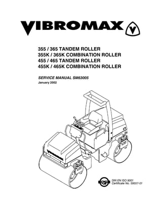
  • 1. SERVICE MANUAL SM63005 355 / 365 TANDEM ROLLER 355K / 365K COMBINATION ROLLER 455 / 465 TANDEM ROLLER 455K / 465K COMBINATION ROLLER January 2002
  • 2. 1 SECTION ONE GENERAL INFORMATION MACHINE DESCRIPTION................................................................................. 1 - 3 SERIAL NUMBERS....................................................................................... 1 - 4 GENERAL SAFETY........................................................................................... 1 - 6 SPARK ARRESTER...................................................................................... 1 - 6 PERSONAL SAFETY .................................................................................... 1 - 7 OPERATING SAFETY .................................................................................. 1 - 8 MAINTENANCE SAFETY................................................................................ 1 - 11 GENERAL INFORMATION.............................................................................. 1 - 14 CLEANING .................................................................................................. 1 - 14 INSPECTION............................................................................................... 1 - 14 BEARINGS .................................................................................................. 1 - 14 NEEDLE BEARINGS................................................................................... 1 - 14 GEARS........................................................................................................ 1 - 14 OIL SEALS, O-RINGS, & GASKETS .......................................................... 1 - 14 SHAFTS ...................................................................................................... 1 - 15 SERVICE PARTS........................................................................................ 1 - 15 LUBRICATION ............................................................................................ 1 - 15 STANDARD TORQUE DATA .......................................................................... 1 - 15 METRIC/USA CONVERSIONS ....................................................................... 1 - 17 MACHINE SPECIFICATIONS ......................................................................... 1 - 18 355/365 SPECIFICATIONS......................................................................... 1 - 18 ENGINE DATA ............................................................................................ 1 - 19 OPERATING DATA..................................................................................... 1 - 19 455/465 SPECIFICATIONS......................................................................... 1 - 20 ENGINE DATA ............................................................................................ 1 - 21 OPERATING DATA..................................................................................... 1 - 21 FLUID CAPACITY............................................................................................ 1 - 22 PNEUMATIC TIRE PRESSURE...................................................................... 1 - 22 DIESEL FUEL SPECIFICATION ..................................................................... 1 - 23 ENGINE OIL SPECIFICATION........................................................................ 1 - 24 SECTION TWO ENGINE R&I ENGINE COOLING SYSTEM............................................................................ 2 - 2 ENGINE EXHAUST SYSTEM ........................................................................... 2 - 3 ENGINE INTAKE SYSTEM ............................................................................... 2 - 4 ENGINE FUEL SYSTEM ................................................................................... 2 - 5 HYDRAULIC PUMP CONTROLS...................................................................... 2 - 6 ENGINE MOUNTS............................................................................................. 2 - 7 ENGINE REMOVAL........................................................................................... 2 - 8 ENGINE OVERHAUL ........................................................................................ 2 - 9 KUBOTA ENGINE WARRANTY........................................................................ 2 - 9
  • 3. 2 ENGINE INSTALLATION ................................................................................ 2 - 12 SECTION THREE ELECTRICAL CIRCUITS INSTRUMENT PANEL ...................................................................................... 3 - 2 Instrument Panel, Single Amplitude .............................................................. 3 - 2 Instrument Panel, Two Amplitude ................................................................. 3 - 4 Instrument Panel, “K” Model ......................................................................... 3 - 6 Combination Indicator ................................................................................... 3 - 8 Instrument Panel, Right Side ........................................................................ 3 - 9 OPERATOR’S CONSOLE............................................................................... 3 - 10 ELECTRICAL INFORMATION ........................................................................ 3 - 11 Fuses .......................................................................................................... 3 - 12 Relays ......................................................................................................... 3 - 13 UNDERSTANDING ELECTRICAL SCHEMATICS ........................................ 3 - 15 UNDERSTANDING RELAYS.......................................................................... 3 - 18 VIBROMAX RELAYS.................................................................................. 3 - 19 EMERGENCY STOP CIRCUIT....................................................................... 3 - 21 STARTER/ CHARGING CIRCUIT................................................................... 3 - 23 UNDERSTANDING BATTERIES .................................................................... 3 - 23 BATTERY DIAGNOSTICS.......................................................................... 3 - 24 UNDERSTANDING ALTERNATORS ......................................................... 3 - 25 CHARGING SYSTEM DIAGNOSTICS ....................................................... 3 - 26 VOLTAGE CHECKS AT ALTERNATOR ................................................... 3 - 27 SYSTEM LEAKAGE.................................................................................... 3 - 27 CIRCUIT WIRING TEST ............................................................................. 3 - 27 MEASURING ALTERNATOR OUTPUT ..................................................... 3 - 28 UNDERSTANDING STARTERS................................................................. 3 - 28 STARTER SOLENOID................................................................................ 3 - 29 STARTER SYSTEM DIAGNOSTICS .............................................................. 3 - 29 SOLENOID CIRCUIT TEST........................................................................ 3 - 29 STARTER CIRCUIT WIRING TEST ........................................................... 3 - 30 STARTER MOTOR TEST........................................................................... 3 - 31 NEUTRAL SWITCH CIRCUIT......................................................................... 3 - 33 NEUTRAL SWITCH CIRCUIT......................................................................... 3 - 35 INSTRUMENTATION PANEL ......................................................................... 3 - 37 PARKING BRAKE CIRCUIT............................................................................ 3 - 39 VIBRATION CONTROL CIRCUIT (one amplitude)......................................... 3 - 39 VIBRATION CONTROL CIRCUIT (two amplitude) ......................................... 3 - 41 SPRINKLER CIRCUIT..................................................................................... 3 - 43 LIGHTING CIRCUIT........................................................................................ 3 - 45 HAZARD/ DIRECTIONAL CIRCUIT................................................................ 3 - 45 BACK-UP ALARM ........................................................................................... 3 - 46 WIRE HARNESS LAYOUT ............................................................................. 3 - 47 WIRE HARNESS 7140/81115......................................................................... 3 - 48
  • 4. 3 WIRE CHART 7140/81115 .............................................................................. 3 - 50 WIRE HARNESS 7140/81255 ......................................................................... 3 - 52 WIRE CHART 7140/81255 .............................................................................. 3 - 54 WIRE HARNESS 7140/82115 ......................................................................... 3 - 57 WIRE CHART 7140/82115 .............................................................................. 3 - 60 WIRE HARNESS 7140/82255 ......................................................................... 3 - 62 WIRE CHART 7140/82255 .............................................................................. 3 - 64 ELECTRICAL SCHEMATICS .......................................................................... 3 - 69 SECTION FOUR HYDRAULIC SYSTEMS PROPULSION DRAWINGS............................................................................... 4 - 2 PROPULSION SYSTEM.................................................................................... 4 - 5 PROPULSION SYSTEM DIAGNOSTICS ..................................................... 4 - 5 INTERNAL LEAKAGE ................................................................................... 4 - 5 PUMP SERVO CONTROL ............................................................................ 4 - 6 VIBRATION DRAWINGS (one amplitude)....................................................... 4 - 10 VIBRATION SYSTEM (one amplitude)............................................................ 4 - 13 VIBRATION DRAWINGS (two amplitude) ....................................................... 4 - 16 VIBRATION SYSTEM (two amplitude) ............................................................ 4 - 19 VIBRATION SYSTEM DIAGNOSTICS........................................................ 4 - 22 VIBRATION FREQUENCY.......................................................................... 4 - 22 STEERING DRAWINGS (without offset) ......................................................... 4 - 23 STEERING SYSTEM (without offset) .............................................................. 4 - 26 STEERING SYSTEM DIAGNOSTICS......................................................... 4 - 26 STEERING DRAWINGS (with offset) .............................................................. 4 - 27 STEERING SYSTEM (with offset) ................................................................... 4 - 29 BRAKE SYSTEM DRAWINGS ........................................................................ 4 - 30 PARKING BRAKES SYSTEM ......................................................................... 4 - 35 PARKING BRAKE DIAGNOSTICS ............................................................. 4 - 35 HYDRAULIC TEST PORTS............................................................................. 4 - 36 COOLER LINES .............................................................................................. 4 - 49 SUCTION LINES ............................................................................................. 4 - 53 HYDRAULIC FILTERS .................................................................................... 4 - 56 HYDRAULIC COMPONENTS ......................................................................... 4 - 57 HYDRAULIC SCHEMATICS............................................................................ 4 - 58 HYDRAULIC COMPONENTS POCLAIN MC05 PROPULSION MOTOR........................................................ 4 - 66 SAUER/SUNDSTRAND SERIES 42 PROPULSION PUMP ........................... 4 - 69
  • 5. 4 SECTION FIVE POWER TRAIN DRUM CROSS-SECTION................................................................................. 5 - 6 DRUM REMOVAL ........................................................................................... 5 - 13 DRIVE MOTOR REMOVAL............................................................................. 5 - 13 DRIVE MOTOR REPAIR................................................................................. 5 - 15 DRIVE MOTOR INSTALLATION..................................................................... 5 - 15 DRUM DRIVE BEARING REMOVAL.............................................................. 5 - 15 DRUM BEARING INSTALLATION.................................................................. 5 - 17 DRUM INSTALLATION ................................................................................... 5 - 17 PNEUMATIC TIRE DRIVE .............................................................................. 5 - 18 SECTION SIX PARKING BRAKE SYSTEM PARK BRAKE TESTING................................................................................... 6 - 7 BRAKE RELEASE FOR TOWING .................................................................... 6 - 7 TOWING PROCEDURE ............................................................................... 6 - 8 BRAKE REPAIRS............................................................................................ 6 - 10 BRAKE DISASSEMBLY.............................................................................. 6 - 10 BRAKE ASSEMBLY.................................................................................... 6 - 10 SECTION SEVEN VIBRATORY SYSTEM VIBRATION SHAFT (two amplitude)................................................................. 7 - 5 DRUM REMOVAL ............................................................................................. 7 - 7 VIBRATION SHAFT REMOVAL........................................................................ 7 - 7 LEFT VIB. BEARING REMOVAL ...................................................................... 7 - 9 LEFT BEARING INSTALLATION...................................................................... 7 - 9 RIGHT BEARING INSTALLATION.................................................................. 7 - 11 DRUM INSTALLATION ................................................................................... 7 - 11 SECTION EIGHT STEERING SYSTEM HORIZONTAL PIVOT DISASSEMBLY......................................................... 8 - 7 STEERING PIVOT DISASSEMBLY.............................................................. 8 - 7
  • 6. 5 SECTION NINE CHASSIS ROLL-OVER PROTECTION STRUCTURE (ROPS)......................................... 9 - 3 ROPS maintenance....................................................................................... 9 - 3 ROPS damage .............................................................................................. 9 - 3 Tightening torques......................................................................................... 9 - 4 SECTION TEN ATTACHMENTS FRONT HARNESS 7140/90106 ...................................................................... 10 - 2 REAR HARNESS 7140/90111......................................................................... 10 - 2 8364/01150 WORKLIGHT CONNECTOR....................................................... 10 - 2 INSTALLATION OF 87140/90100 WORK LIGHT KIT..................................... 10 - 2 INSTALLATION OF 87140/90150 ROAD LIGHT KIT...................................... 10 - 3 FUSE LAYOUT................................................................................................ 10 - 7 RELAY LAYOUT.............................................................................................. 10 - 8 SPRINKLER SYSTEM..................................................................................... 10 - 9
  • 7. 1 - 1 SECTION ONE GENERAL INFORMATION
  • 8. SM63005 - SECTION ONE GENERAL INFORMATION 1 - 2 Built with serviceability in mind.
  • 9. SM63005 - SECTION ONE GENERAL INFORMATION 1 - 3 MACHINE DESCRIPTION The Vibromax Model 355/365 is a 3.5 metric ton tandem drum roller with articulated steering, hydrostatic propulsion and a hydrostatic vibratory system. The Model 455/ 465 is a larger 4.5 metric ton tandem drum roller. Both the 3.5 and 4.5 ton machines offer a “K” model option. The “K” model is a combination machine offering a steel front drum and pneumatic tires in place of the rear drum. Power is provided by a 134.4 cubic inch (2197 cc) Kubota, four cylinder diesel engine, Model V2203-E, rated at 46.6 hp SAE net (34.3 kW) at 2600 RPM. The operator’s platform was designed using modern techniques to assure good visibility and operator comfort. The operator’s seat box can be tilted forward to gain easy access to the machine’s hydraulic pumps and valves. Both tandem roller models operate at a vibration frequency of 3300 vibrations per minute (55 Hz). Vibratory operation is available for either the front drum or both drums. A two frequency/two amplitude option is available for both the 3.5 and 4.5 metric ton machines. The second vibration frequency is 3000 vpm. (50 Hz). On the “K” model only the front drum will vibrate. The hydrostatic drive system allows for infinitely variable ground speed. All machines are equipped with a two speed arrangement which provides greater control in the 0 to 4 mph range. The hydrostatic drive system consists of a piston pump and front and rear drum drive motors. Hydraulic release, spring applied parking brakes are incorporated into the design of the drum motors. On the “K” model two smaller hydraulic motors are used to drive the right and left side pneumatic tires. Brakes are also incorporated into “K” model drive motors. As a factory option, these machines offer an articulation offset of five inches (127 mm) to the left or right of center position. This feature is most useful when compacting asphalt on tight turns. These machines are equipped with an intermittent sprinkler system for use in asphalt applications. The water tanks are made of a rust proof synthetic material. The system is a pressure spray type with sprinkler tubes fitted with nozzles. The system controls are designed to allow variable off times in the automatic mode to minimize water usage. The pneumatic “K” model offers separate sprinkler systems for the front and rear of the machine to allow the use of special soap solutions on the rear tires. Both systems have variable controls. Each drum is equipped with front and rear scrapers. The scrapers are spring loaded against the drum and can easily be moved away from the drum for soil and gravel compaction jobs. Scrapers are also available on the “K” model. A cocoa mat option is also available. As sold in the United States the machines are fitted with a Roll Over Protective Structure (ROPS). A seat belt is provided as part of the ROPS system. As sold in the United States the machines are also fitted with a standard Back-up alarm system and an emergency stop system. All models include a centralized testing station for quick and easy diagnostics for the various hydraulic systems. Road lights, work lights, FOPS, and a sun roof are four standard options. Other additional equipment such as beacon lights, slow moving machine signs, etc., are available as special order items. If you have special needs please contact your dealer.
  • 10. SM63005 - SECTION ONE GENERAL INFORMATION 1 - 4 SERIAL NUMBERS 1 Model / Serial Number 2 Front Drum Drive Motor S/N 3 Rear Drum Drive Motor S/N 4 Steering Unit S/N 5 Front Vibratory Motor S/N 6 Rear Vibratory Motor S/N 7 Hydraulic Pumps S/N 8 Engine S/N
  • 11. SM63005 - SECTION ONE GENERAL INFORMATION 1 - 5 IDENTIFYING MACHINE COMPONENTS 1 Articulation joint 11 Spring loaded brake 2 Smooth drum 12 Water tank 3 Lifting/tie-down eye 13 Fuel tank 4 Operator’s stand 14 Air filter canister 5 Battery 15 Water - oil cooler 6 Hydraulic tank 16 Roll over protection 7 Engine 17 Vibration motor 8 Drum drive motor 18 Steering cylinder 9 Rubber buffer 19 Hydraulic pumps 10 Scraper 20 Sun roof
  • 12. SM63005 - SECTION ONE GENERAL INFORMATION 1 - 6 GENERAL SAFETY The information in this manual does not replace any safety rules and laws used in your area. Before operating this machine, learn the rules and laws for your area and make sure your machine has the correct equipment according to these rules and regulations. Before starting the engine study the operator’s manual. • Know the location and function of all machine controls. • Clear the area of other persons before you start the engine. • Check all controls in a safe area before you operate the machine. • Understand the limits of the machine. • Do not try to do too much too fast. • Keep the machine under control at all times. The following decal is located on the right side of the water tank. Check the decal daily. Clean or replace as needed. SPARK ARRESTER NOTE: Rules or laws in some areas may require that this machine be equipped with a spark arrester or spark arrester muffler. Check the rules or laws in your area.
  • 13. Thank you very much for your reading. Please Click Here. Then Get COMPLETE MANUAL. NO WAITING NOTE: If there is no response to click on the link above, please download the PDF document first and then click on it.
  • 14. SM63005 - SECTION ONE GENERAL INFORMATION 1 - 7 PERSONAL SAFETY Loose clothing and jewelry can cause an accident. Do not wear loose clothing or jewelry that can catch on controls, etc. Do wear safety shoes, hard hat, heavy gloves, etc. when required for your protection. Foreign materials and loose objects on the steps, hand rails, and in the operators com- partment can cause accidents and injury. Keep the steps, hand rails, and operator’s compartment clear at all times. Know and understand the arrangements for movement of trucks, machines, and per- sons on your job site. Understand and follow the instructions of flagmen, road signs, or signals. Check machine controls for proper operation prior to starting the machine. A fire can cause injury or death. Always have a fire extinguisher on the job site near the machine. Make sure the fire extinguisher is serviced according to the manufacturer’s instructions. Holes, obstructions, debris, and other work area hazards can cause injury or death. Always walk-around and look for these and other hazards before you operate your machine in a new work area. Lack of, or incomplete, machine inspection and maintenance can cause accidents. Always follow the instructions in this manual for machine inspection and maintenance. Always use the seat belt when operating the machine. Make sure the buckle is fully secured.
  • 15. SM63005 - SECTION ONE GENERAL INFORMATION 1 - 8 The following decal is located on the upper rear side of the steering column. Check the decal daily. Clean or replace as needed. Always wear the proper ear protection when operating this machine. Permanent hearing loss can result from extended exposure to loud noises. The following decal is located on the instrument panel to the right side of the main gauge cluster. Check the decal daily. Clean or replace as needed. OPERATING SAFETY Dust, smoke, fog, etc. can decrease your vision and cause an accident. Always stop or slow the machine until you can clearly see your work area and the surrounding traffic.
  • 16. SM63005 - SECTION ONE GENERAL INFORMATION 1 - 9 Operate the controls from the operator’s seat only, and keep your hands on the controls during operation. The following decal is located on the left side of the water tank. Check the decal daily. Clean or replace as needed. Do not permit other people to ride on the machine as passengers. Sparks from the electrical system or engine exhaust can cause a fire or explosion. Before you operate this machine in an area with flammable dust or vapors, use good ventilation to remove the flammable dust or vapors. Engine exhaust fumes can cause injury or death. If you operate this machine in an enclosed area, use good ventilation to replace the exhaust fumes with fresh air. The vibrations from this machine can cause the walls of a trench or high bank to col- lapse. Make sure the walls of the trench or bank are braced. If you do not follow these instructions, you can cause personal injury or death to persons working in these areas. This machine uses an articulating joint. Keep all persons clear of this pinch area when the engine is running. Machine movement can cause personal injury. The following decal is located on each side of the machine’s and rear frames floor panel in the articulation joint area. Check the decals daily. Clean or replace as needed.
  • 17. SM63005 - SECTION ONE GENERAL INFORMATION 1 - 10 The following decal is also located on both sides of the rear frame in the area of the articulation joint and symbolizes the danger of the pinch point. Check the decal daily. Clean or replace as needed. The following decal is located on the right side of the water tank. Check the decal daily. Clean or replace as needed
  • 18. SM63005 - SECTION ONE GENERAL INFORMATION 1 - 11 A machine out of control can cause injury or death. You must make a judgement if weather and earth conditions will permit safe operation on a hill, ramp, or rough ground. Adjust machine operation accordingly. Operating this machine too close to High Voltage electrical lines can cause injury or death. Follow the guide lines listed below. NOTE: IF THE CLEARANCES IN THE SPECIFICATIONS BELOW ARE LESS THAN THE CLEARANCES GIVEN IN THE RULES AND LAWS OF YOUR AREA,YOU MUST FOLLOW THE RULES AND LAWS OF YOUR AREA! MAINTENANCE SAFETY The following decal is located on the left side of the front roller frame. Check the decal daily. Clean or replace as needed Table 1: Electrical Safety Rules Cable Voltage Minimum Clearance From Cable When Machine is Working Minimum Clearance From Cable When Transporting Machine 50,000 volts or less 10 feet (3 meters) 4 feet (1.2 meters) 50,000 volts to 345,000 volts 10 feet (3m) plus 1/2 inch (13mm) for every 1000 volts over 50,000 volts 10 feet (3 meters) 345,000 volts to 750,000 volts 10 feet (3m) plus 1/2 inch (13mm) for every 1000 volts over 50,000 volts 16 feet (5 meters)