SlideShare a Scribd company logo
1 of 17
Download to read offline
272350000
Technical Information for Yale Service Centers
This manual is addressed exclusively to the specialised technicians of the Yale service network
EUROPEAN MODELS (EU) A868 - MTC10, A868 - MTC13 A869 - MTC15,
A870 - MTC18
US MODELS (US) A868 (Was A872) - NTA030SA, A869 (Was A873) - NTA040SA,
A870 (Was A874) - NTA040DA
Section: INDEX
SERVICE WARNINGS
NEVER CARRY OUT ANY CLEANING, lubricaTion oR maIntenANCe WITH THE BATTERY
CONNECTED.
NOT WEAR RINGS, WRIST WATCHES, JEWELERY, LOOSE OR DANGLING CLOTHES SUCH
AS SCARVES, UNBUTTONED JACKETS OR OVERALLS WITH OPEN ZIP FASTENERS THAT CAN
TANGLE IN MOVING PARTS. IT IS RECOMMENDED TO WEAR PROTECTIVE CLOTHING, SUCH
AS, STEEL TOED SKID RESISTANT SHOES, SAFETY GLASSES AND GLOVES.
NEVER USE GASOLINE, DIESEL FUEL, OR OTHER INFLAMMABLE MATERIALS AS
CLEANING AGENTS. USE INSTEAD NON-INFLAMMABLE, NON-TOXIC COMMERCIAL SOLVENTS.
DO NOT SMOKE, DO NOT USE FLAMES, DO NOT CAUSE SPARKS, WHEN EASILY
INFLAMMABLE MATERIALS ARE HANDLED.
1/2
2018/7/6
file:///F:/1-aservicemanualpdf.com/manual/ / /YALE%20(A872)...
In case of service outside the workshop, position the truck on a flat surface if possible and block it. If
work on a slope is unavoidable, block the truck first and then move it to a level area as soon as
possible.
Disconnect the batteries and label all the controls to signal that service is taking place. Block the truck
as well as any attachment that has to be lifted.
Use only the prescribed attachment points when towing and make sure the pins and/or bolts are locked
tightly before pulling. Lift and handle all heavy parts by means of a lifting device with the suitable
capacity. Use the lifting eyes provided for the lifting. Do not lift over other people or permit them near a
lifted load.
Avoid twisting chains or wire ropes.
Do not used damaged chanins or wire ropes while lifting or pulling. When handling chains or wire ropes
always use goves.
Handle all parts carefully. Never put your hands or fingers in between parts.
Wear the special-purpose clothes, such as, safety glasses, gloves and steel toesd skid resistant shoes.
The area where maintenance operations are carried out must be always kept clean and dry. Clean up
any water, oi, or fuel spills immediately.
Do not pile grease or oil-covered clothes. They represent a fire risk. Always put them in a closed metal
container.
Never carry out any service operation on the machine with anyone in the operator position, unless the
operator is fully trained and involved in the operation to be carried out.
Welding
When welding operations are required, use appropriate protective clothing, such as, dark glasses,
helmets, overalls, gioves and steel toed skid resistant shoes.
Dark glasses should also be worn by anyone in the vicinity during a welding operation, even if they are
not performing the work.
Never look at the welding arc without properly protecting your eyes.
Battery
lf you have to use batteries, remember the cables shouId be connected to the terminals as specified:
(+) with (+) and (-) with (-)
Avoid short circuiting the (+) and (-) battery terminals together.
The gas released from the batteries is highiy infiammabie. During recharging, leave the battery
compartment uncovered to ensure more effective ventilation and remove the caps.
DO AVOID SPARKS OR FLAMES IN THE BATTERY AREA!
Never check the state of charge of the batteries using “bridges” by placing metal objects on the battery
terminals.
Before any service operation, check that no parts are short circuited. Eliminate short circuits before
proceeding with work.
Always disconnect the batteries before carrying out any electrical or mechanical service on the truck.
For the battery chargers and similar equipment use only power sources having an effective earth
connection to minimize the possibility of electrical shocks.
Hydraulic System
High pressure hydraulic fluid coming from a very small hole may be almost invisible and be sufficiently
powerful enough to penetrate the skin causing serious injury. Never use your hands or any part of your
body to search for hydraulic leaks. Us a piece of paper or wood to for leaks.
Use the special-purpose equipment to check hydraulic system pressures.
NOTE: THIS MANUAL DOES NOT REPLACE THE OWNER AND OPERATOR MANUAL.
2/2
2018/7/6
file:///F:/1-aservicemanualpdf.com/manual/ / /YALE%20(A872)...
INDEX
INTRODUCTION
Section: TRUCK INSTALLATION
1.0 INTRODUCTION
1.1 VNA INSTALATION
1.2 VNA UNPACKING AND SET UP
1.3 VNA DELIVERY
2.0 VNA REMOVAL FROM CONTAINER / TRUCK
3.0 VNA STAND UP PROCEDURE
4.0 LOWER CAB AFTER STAND UP
5.0 INSTALLATION OF ATTACHMENT
6.0 ADD OIL TO HYDRAULIC TANK
7.0.A BATTERY INSTALLATION US: NTA030SA - NTA040SA EU: MTC10, MTC13, MTC15
7.0.B BATTERY INSTALLATION - US: NTA040DA EU: MTC18
8.0 INSTALLATION IN AISLE
8.1 LOAD UNIT DEPOSIT ADJUSTMENT
8.2 IMPORTANT (GUIDE ROLLERS / WIRE GUIDANCE)
9.0 OPERATOR TRAINING
Section: ELECTRICAL SYSTEM ELECTRIC STEERING SYSTEM EPS-DC
FOR FURTHER INFORMATION REGARDING THE ELECTRONIC SYSTEM OF THE EPS-DC ELECTRICAL
STEERING SYSTEM, CONSULT SERVICE MANUAL P/N 272491100
Section: ELECTRICAL SYSTEM
1.0 ELECTRICAL COMPARTMENT ARRANGEMENT MODELS NTA030SA - NTA040SA -MTC10 - MTC13 -
MTC15
1.0.1 ELECTRICAL COMPARTMENT ARRANGEMENT MODELS NTA040DA - MTC18
1.1 DESCRIPTION OF COMPONENTS
1.1.1 PHOTOCELLS
1.1.1A PHOTOCELL ADJUSTMENT
1.1.1B MALFUNCTION CAUSED BY INCORRECT ADJUSTMENT
1.1.2 THROTTLE ASSEMBLY
1.1.3 BATTERY DISCHARGE INDICATOR (BDI)
1.1.3A LOCK OUT LEVEL ADJUSTMENT
1.1.3B BDI TROUBLESHOOTING
1.1.4 DC / DC CONVERTER
1.2 TABLE OF ELECTRICAL SYSTEM COMPONENTS
2.0 TRACTION MOTOR ELECTRONIC CONTROL
2.0.1 INTRODUCTION
2.1 DEFINITION OF THE TRUCK DIRECTION OF TRAVEL
2.2 CONTROLLER GENERAL FEATURES
2.3 CONTROLLER FUNCTIONAL FEATURES
2.4 CONTROLLER DIAGNOSTICS
2.5 CHOPPER H2B MECHANICAL DIAGRAM
2.6 CONNECTORS
2.7 CONNECTOR INCONNECTOR “E” INPUT DESCRIPTION
2.9 BASIC DIAGRAM OF THE TRACTION CONTROLLER CONNECTIONS
3.0 HAND SET
3.0.1 INTRODUCTION
3.2 USE OF THE HAND SET
3.2.1 CONNECTION TO CONTROLLER
4.0 CONSOLE FUNCTION CHART - TRACTION MOTOR CONTROLLER
4.1 CONTROLLER PROGRAMMING
4.1.0 CONFIGURATION MENU
4.1.1 CONFIG. MENU / SET MODEL
4.1.2 CONFIG. MENU / SET OPTIONS
4.1.3 CONFIG. MENU / ADJUSTMENT
4.1.4 MAIN MENU / PARAMET. CHANGE
4.1.5 MAIN MENU / TESTER
4.1.6 MAIN MENU / SAVE PARAMETER
4.1.7 MAIN MENU / RESTORE PARAM
4.1.8 MAIN MENU / ALARM
4.1.9 MAIN MENU / PROGRAM VACC
1/5
2018/7/6
file:///F:/1-aservicemanualpdf.com/manual/ / /YALE%20(A872)...
4.2 CONFIGURATION TABLES FOR TRACTION CONTROLLER
4.3 PROGRAMMING LEVELS CORRESPONDENCE TABLE
4.4 SET UP OF A NEW CONTROLLER BEFORE OPERATION
5.0 TROUBLESHOOTING
5.1 DECODING DIAGNOSTIC LED ALARM CODES FOR TRACTION CONTROLLER
5.2 DECODING HAND SET ALARMS FOR TRACTION CONTROLLER
6.0 PUMP MOTOR CONTROLLER - DESCRIPTION
6.1 CONTROLLER FUNCTIONAL FEATURES
6.2 PUMP MOTOR CONTROLLER CIRCUIT
6.3 PUMP MOTOR CONTROLLER CONNECTORS
6.4 CONNECTOR INPUT DESCRIPTIONS (EXCEPT E)
6.5 CONNECTOR “E” INPUT DESCRIPTION
6.6.A CONSOLE FUNCTION CHART - PUMP MOTOR CONTROLLER
6.6 HAND SET PROGRAMMING OF THE PUMP MOTOR CONTROLLER
6.6.1 CONFIGURATION MENU
6.7 CONFIGURATION TABLE - PUMP MOTOR CONTROLLER
6.8 PARAMETER VALUE VERSUS PROGRAMMED LEVEL TABLE
6.14 TROUBLESHOOTING
6.14.1 DECODING DIAGNOSTIC LED ALARM CODES FOR PUMP CONTROLLER
6.14.2 DECODING HAND SET ALARMS FOR PUMP MOTOR CONTROLLER
7.0 CONFIGURATION TABLES - EPS ELECTRIC POWER STEERING CONTROLLER
7.1 EPS CONFIGURATION WITH SMART STEER (POT) STEERING
7.2 EPS CONFIGURATION WITH TACHO GENERATOR STEERING
Section: PLC
1.0 STANDARD INTERLOCK FUNCTIONS
2.0 ENABLE FUNCTION MANAGEMENT
2.1 DESCRIPTION OF THE SYSTEM THAT RUNS THE ENABLES PLC (PROGRAMMABLE LOGIC
CONTROLLER)
2.2 GENERAL CHARACTERISTICS
3.0 PROGRAMMING
4.0 ELECTRIC ADJUSTMENT OF THE CAB AND AUXILIARY MAST LOWERING PROPORTIONAL ELECTRO-
HYDRAULIC VALVES
5.0 PLC DIGITAL INPUT / OUTPUT REFERENCE EU / US VERSIONS
5.1.A PLC TRUTH TABLE AND INTERFACE RELAY BOARD (US VERSION ONLY)
5.1.B PLC TRUTH TABLE AND INTERFACE RELAY BOARD (EU VERSION ONLY)
6.0 REMOVING/INSTALLING THE PLC
7.0 PLC BATTERY FUNCTION AND CHANGING
8.2 PROCEDURE FOR CHANGING FUSES
Section: DIAGNOSTICS
1.0 CAB DOES NOT LOWER
2.0 FORKS DO NOT EXTEND LEFT
3.0 FORKS DO NOT EXTEND RIGHT
4.0 FORKS DO NOT LOWER
5.0 FORKS DO NOT RAISE
6.0 FORKS DO NOT RETRACT FROM LEFT
7.0 FORKS DO NOT RETRACT FROM RIGHT
8.0 FORKS DO NOT ROTATE LEFT
9.0 FORKS DO NOT ROTATE RIGHT
10.0 HIGH TEMPERATURE
11.0 MINI MAST DOES NOT TRAVERSE LEFT
12.0 MINI MAST DOES NOT TRAVERSE RIGHT
13.0 SYNC CAB / FORKS DO NOT LOWER
14.0 SYNC TRAVERSE / ROTATE DOES NOT WORK
15.0 TRUCK DOES NOT TRAVEL
Section: SLOW DOWN / STOP
1.0 AUTOMATIC SLOW DOWN AND STOP SYSTEM DESCRIPTION
1.1 MAGNET INSTALLATION IN AISLE
1.1.1 MAGNET LAYOUT FOR SYSTEMS WITH 2 MAGNETS IN AISLE
1.1.2 MAGNET LAYOUT FOR SYSTEMS WITH 4 MAGNETS IN AISLE
2.0 SYSTEM DESCRIPTIONS
2.1 (US) END OF AISLE AUTO-BRAKING
2.2 (EU) END OF AISLE AUTO-BRAKING
2.3 SLOW DOWN / STOP (SET / RESET)
3.0 SYSTEM FUNCTIONS (WITH STANDARD PLC PROGRAM)
2/5
2018/7/6
file:///F:/1-aservicemanualpdf.com/manual/ / /YALE%20(A872)...
3.1 SYSTEMS WITH 2 MAGNETS IN AISLE
3.2 SYSTEMS WITH 4 MAGNETS IN AISLE
4.0 TROUBLESHOOTING
Section:HYDRAULIC SYSTEM
1.0 GENERAL DESCRIPTION
1.1 HYDRAULIC SYSTEM SYMBOL LEGEND
- FUNCTIONAL HYDRAULIC DIAGRAM
- HYDRAULIC SYSTEM COMPONENTS
1.2 TABLE OF HYDRAULIC SYSTEM COMPONENTS
1.3 FLOW CONTROL AND HOSE BREAK VALVES
1.4 COMPONENT ACTUATION TABLE: PUMPS AND ELECTRO-SOLENOIDS
1.4.1 HYDRAULIC SYSTEM FUNCTIONAL LAYOUT
2.1 MAIN HYDRAULIC VALVE ASSEMBLY
2.1.0 MAIN HYDRAULIC VALVE ASSEMBLY COMPONENTS
2.2 CAB LIFT PRESSURE RELIEF VALVE ADJUSTMENT
2.3 ADJUSTING THE CAB LOWER PROPORTIONAL VALVE
2.3.1 EMERGENCY LOWER SCREW
2.4 TROUBLE-SHOOTING
3.1 AUXILIARY MAST/ATTACHMENT VALVE ASSEMBLY
3.1.0 AUXILIARY MAST/ATTACHMENT VALVE COMPONENT TABLE
3.2 AUXILIARY MAST/ATTACHMENT VALVE MAIN PRESSURE RELIEF ADJUSTMENT
3.3 ADJUSTING AUXILIARY MAST LOWER PROPORTIONAL VALVE
3.4 TROUBLE-SHOOTING
4.1 CAB LIFT CYLINDER EXPLODED DRAWING NTA030SA - MTC10 - MTC13 (2 STAGE MAST)
4.2 CAB LIFT CYLINDER TABLE OF COMPONENTS FOR NTA030SA - MTC10 - MTC13
5.1 CAB LIFT CYLINDER EXPLODED DRAWING NTA030SA - MTC10 - MTC13 (3 STAGE MAST)
5.2 CAB LIFT CYLINDER TABLE OF COMPONENTS FOR NTA030SA - MTC10 - MTC13
6.1 CAB LIFT CYLINDER EXPLODED DRAWING NTA040SA - NTA040DA - MTC15 - MTC18 (2 STAGE
MAST)
6.2 CAB LIFT CYLINDER TABLE OF COMPONENTS FOR NTA040SA - NTA040DA - MTC15 - MTC18
7.1 CAB LIFT CYLINDER EXPLODED DRAWING NTA040SA - NTA040DA - MTC15 - MTC18 (3 STAGE
MAST)
7.2 CAB LIFT CYLINDER TABLE OF COMPONENTS FOR NTA040SA - NTA040DA - MTC15 - MTC18
8.1 DISSASSEMBLING THE MAIN LIFT CYLINDERS
8.2 CHANGING THE SEALS
8.3 INSTALLING THE MAIN LIFT CYLINDERS ON THE MACHINE
8.4 BLEEDING THE AIR FROM THE MAIN HOIST CYLINDER
9.1 AUXILIARY MAST LIFT CYLINDER EXPLODED DRAWING
9.2 AUXILIARY MAST LIFT CYLINDER PART TABLE FOR
10.1 DISMANTLING AUXILIARY MAST LIFT CYLINDER
10.2 CHANGING THE SEALS
10.3 REASSEMBLING THE AUXILIARY MAST LIFT CYLINDER
10.4 BLEEDING THE AIR FROM THE AUXILIARY MAST LIFT CYLINDER
Section: ATTACHMENT
1.1 ATTACHMENT COMPONENTS
1.2 ATTACHMENT COMPONENT TABLE
2.1 TRILATERAL ATTACHMENT FUNCTIONING
3.1 TRUCK INSTALLATION
3.1.1 ATTACHMENT ASSEMBLY PROCEDURES
4.1 MECHANIC ADJUSTMENT OF THE ATTACHMENT SUPPORT BEARINGS
5.1 MECHANIC STROKE END ADJUSTMENT
5.2 ROTATING MECHANIC STROKE END AND CAMS
5.3 TRASLATION SPEED REDUCER MICROSWITCH
6.1 MECHANICAL ADJUSTMENTS OF THE LOAD HANDLER BEARINGS
7.1 MAINTENANCE
8.1 TROUBLESHOOTING
Section: MAST
1.0 MAST REMOVAL PROCEDURE MOD. EU MTC10 - MTC13 - MTC15 - MTC18 MOD. US NTA030SA -
NTA040SA - NTA040DA
1.1 REMOVING THE CAB FROM THE MAST
2.0 REMOVING THE CYLINDERS MOD. EU MTC10 - MTC13 - MTC15 MOD. US NTA030SA - NTA040SA
2.1 REMOVING THE MAST MOD. EU MTC10 - MTC13 - MTC15 MOD. US NTA030SA - NTA040SA
3.0 REMOVING THE BOTTOM GUIDE BEARING OF THE INNER MAST SECTION MOD. EU MTC10 - MTC13
1 MOD. US NTA030SA
3/5
2018/7/6
file:///F:/1-aservicemanualpdf.com/manual/ / /YALE%20(A872)...
4.0 REMOVING THE ROLLERS FROM THE CAB AND INNER TELESCOPING SECTION MOD. EU MTC15 -
MTC18 MOD. US NTA040SA - NTA040DA
5.0 REMOVING SIDE ROLLERS FROM THE MAST MOD. EU MTC15 - MTC18 MOD. US NTA040SA -
NTA040DA
Section: BILATERAL EQUIPMENT
1.0 DESCRIPTION OF EQUIPMENT
1.0.1 COMPOSITION
1.0.2 TELESCOPING ACTION
1.1 TOP TELESCOPING SECTION OR LOAD PLATFORM
1.2 INTERMEDIATE TELESCOPING SECTION
1.3 TELESCOPING SECTION SUPPORT
1.4 TELESCOPING ASSEMBLY
1.5 TABLE OF COMPONENTS
2.0 MAINTENANCE
2.0.1 HOW TO DISMANTLE THE EQUIPMENT
2.0.2 TIGHTENING TORQUES
2.0.3 PRECAUTIONS WHEN USING MAINTENANCE PRODUCTS
2.0.4 COMPONENTS REQUIRING MAINTENANCE
2.0.5 ROUTINE MAINTENANCE OPERATIONS
2.0.6 ITEMS NOT REQUIRING RELUBRICATION
2.0.7 SYMBOLS
2.0.8 FAULT-FINDING AND REMEDIES
3.0 REMOVING THE VARIOUS SECTORS
4.0 DISASSEMBLING EQUIPMENT
5.0 REMOVAL PROCEDURE
Section: WHEELS
1.0 REMOVING THE LOAD WHEELS
2.0 REMOVING THE DRIVE WHEELS MOD. US - NTA030SA - NTA040SA4 EU - MTC10 (EU ONLY) -
MTC13 - MTC15
3.0 REMOVING THE DRIVE WHEELS MOD. US - NTA040DA EU - MTC18
Section: BRAKING SYSTEM
1.0 BRAKING SYSTEMS DESCRIPTION
2.0 REMOVAL AND ADJUSTMENT OF THE ELECTROMAGNETIC BRAKE
3.0 ADJUSTMENT AND PUTTING INTO SERVICE
Section: TRANSMISSION
1.1 DISMANTLING THE TRANSMISSION FROM THE TRUCK US - NTA030SA - NTA040SA EU - MTC10 (EU
ONLY) - MTC13 - MTC15
1.2 INTRODUCTION
1.3 DISMANTLING THE CONNECTIONS
1.4 CHAIN
1.5 REMOVING THE TRANSMISSION UNIT
1.6 TRANSMISSION OIL
1.7 REMOVING THE MOTOR
1.7A REMOVING THE PLATE
1.8 DISMANTLING THE CHAIN
1.9 DISMANTLING THE WHEEL
2.0 DISMANTLING THE TRANSMISSION FROM THE TRUCK MOD. NTA040DA - MTC18
3.0 GENERAL INFORMATION NTA030SA - NTA040SA - MTC10 - MTC13 - MTC15
3.1 TRANSMISSION COMPONENTS
3.2 CONSUMABLE GOODS
3.4 STANDARD TOOLS AND FIXTURES
4.0 DISASSEMBLY
4.1 INTRODUCTION
4.2 REMOVAL AND DISASSEMBLY OF THE TRANSMISSION HOUSING UPPER PART
4.3 REMOVING OF THE TRANSMISSION COVER
4.4 DISMANTLING THE CROWN GEAR AND WHEEL SHAFT
4.5 REMOVING THE TAPER ROLLER BEARING INNER RACE FROM THE WHEEL SHAFT AND CROWN GEAR
4.6 DISASSEMBLY OF THE PINION SHAFT
4.7 DISASSEMBLY OF THE TAPER ROLLER BEARING OUTER RACE FROM THE TRANSMISSION HOUSING
4.8 REMOVING THE THREAD PROTECTIVE SHIELD
5.0 ASSEMBLY
5.1 INTRODUCTION
5.2 MEASURING THE ASSEMBLY DIMENSION OF THE PINION SHAFT
5.3 PRE-ASSEMBLY OF THE TRANSMISSION HOUSING
4/5
2018/7/6
file:///F:/1-aservicemanualpdf.com/manual/ / /YALE%20(A872)...
5.4 PRE-ASSEMBLY OF THE WHEEL SHAFT
5.5 MOUNTING THE TAPER ROLLER BEARING INNER RACE ON THE CROWN GEAR
5.6 PRE-ASSEMBLY OF THE PINION SHAFT
5.7 MOUNTING THE PINION SHAFT IN THE TRANSMISSION HOUSING
5.8 MEASURING THE BEARING CLEARANCE OF THE PINION SHAFT AND ADJUSTING THE PRE-STRESS
5.9 MOUNTING THE WHEEL SHAFT AND THE CROWN GEAR ON THE TRANSMISSION HOUSING
5.10 MEASURING AND ADJUSTING THE CROWN GEAR CIRCUMFERENTIAL BACKLASH
5.11 CHECKING THE TOOTH PATTERN
5.12 MEASURING THE WHEEL SHAFT BEARING CLEARANCE AND ADJUSTING THE BEARING PRE-
STRESS
5.13 MOUNTING THE THREAD PROTECTIVE SHIELD IN THE TRANSMISSION HOUSING
5.14 MOUNTING THE RADIAL SHAFT SEAL IN THE TRANSMISSION HOUSING
5.15 MOUNTING THE HOUSING COVER
5.16 TRANSMISSION UPPER PART
6.0 ADJUSTMENT DATA
6.1 TIGHTENING TORQUE
7.0 TROUBLESHOOTING
8.0 STORAGE
8.1 DECOMMISSIONING
5/5
2018/7/6
file:///F:/1-aservicemanualpdf.com/manual/ / /YALE%20(A872)...
VNA INSTALLATION
1.0 INTRODUCTION
1.1 VNA INSTALATION
This section gives the field technician all information necessary to correctly install a VNA truck following the most
rapid procedure.We suggest to follow the procedure step by step in the order that follows.1.0 INTRODUCTION
1.2 VNA UNPACKING AND SET UP
This is the proposed method for removing a VNA Lift Truck from a hard top shipping container using a motorized
hand truck and two lift trucks with adeguate lifting straps, blocks of wood 100mm x 100mm (4"X4") and cardboard
to protect paintwork. This approach requires 3 people during the stand up process (2 lift truck operators and
someone on the floor to coordinate).
1.3 VNA DELIVERY
Typical equipment used for the installation of the VNA product:
• Motorized hand pallet truck – 6000 lb (3 tonne) capacity preferred or a conventional truck with fork extensions
• 8,000 lb (4 tonne) capacity forklift with 48” (1200mm) forks – used as the “rear anchor” truck during stand up
process
• 10,000 lb (5 tonne) (or greater) capacity forklift with 72” (1800mm) forks and at least 180" (4500mm) of lift
(220 " - 5500mm of lift is required for VNA masts with overall lowered height above 195" - 4875mm)
• Various lifting straps (in good condition), blocks of wood, metric Allen wrenches, standard tools, oil funnel and
towels
N.B. If an un-loading bay as shown in this procedure is not available or if the VNA must be lifted for
other reasons from the transporter, a crane must be used with at least 19,000 lb (9 tonne) capacity.
The crane will then replace the 10,000 lb (5 tonne) lift truck in the uprighting operation.
1/6
2018/7/6
file:///F:/1-aservicemanualpdf.com/manual/ / /YALE%20(A872)...
View of VNA unit as received in the Container (Typically two are in a container depending on Mast
Height)
2.0 VNA REMOVAL FROM CONTAINER / TRUCK
1. Remove palletized attachment with lift truck or motorized hand truck
2. Remove wheel chocks and tie downs that hold the VNA unit in the container
3. Move the pallet truck so as to put it up against the cross bar on the VNA support frame that it against the
backrest, or use wooden spacers if the backrest cannot be put up against the cross bar.
4. Use straps or the tie downs that came with the VNA unit to affix the support frame to the crossbar between the
loadwheels on the VNA truck (this keeps the support frame from deflecting forward when the VNA unit is unloaded
from the container.
2/6
2018/7/6
file:///F:/1-aservicemanualpdf.com/manual/ / /YALE%20(A872)...
5. Slowly remove the VNA unit from the container (or unload from truck using 19.000 lb - 9 tonne crane).
6. Observe dock plate in relation to the load wheels on the VNA unit when exiting the container, also observe top of
mast of the VNA unit in relation to the top of the container.
3.0 VNA STAND UP PROCEDURE
7. Check that the mechanical end stroke bolts are already fitted (they may be attached to the mast near their final
position for shipment). Place lift strap around forks of lifting truck “A” (10,000 lb - 5 tonne) and through top lifting
eye. Forks of lifting truck are positioned far enough from the lifting eye so that the mast when upright will not hit
the forks of the lifting truck.
8. Place chain around forks of “catch truck” “B” (8,000 lb - 4 tonne) and through back lifting eye of the VNA unit.
Forks of “catch truck” positioned about 5’ (1500mm) above rear of VNA unit (this provides clearance for the forks
over the top of the control compartment of the VNA unit once it stands up).
9. Place cardboard “C” on back of the VNA’s control compartment doors to protect paint
3/6
2018/7/6
file:///F:/1-aservicemanualpdf.com/manual/ / /YALE%20(A872)...
10. A 4"X4” (100mm x 100mm) piece of wood “D” secured to the forks of the “catch truck” to prevent the strap
from slipping off the forks when the VNA truck goes “over center”. Also add a securing strap to the lifting trucks
strap as well.
11. Once all straps are installed, lift the unit just off the floor and remove the VNA shipping support frame “E” from
the main mast.
12. Raise the mast of the lifting truck “A” (10,000 lb - 5 tonne unit) slowly while-
13. Lowering and moving the “catch truck” “B” forward – keep chains tight, do not allow chains to become slack.
14. Keep raising the forks on the lift truck to keep the VNA truck’s load wheels rolling on the ground, while keeping
lifting chains tight.
4/6
2018/7/6
file:///F:/1-aservicemanualpdf.com/manual/ / /YALE%20(A872)...
15. When the VNA truck goes “over center” then the “catch truck” “B” will have most of the weight
16. Once the VNA truck goes “over center” then continue to drive the “catch truck” “B” forward and lower while-
17. Slowly lowering the forks on the lifting truck “A” until the VNA unit is standing.
4.0 LOWER CAB AFTER STAND UP
5/6
2018/7/6
file:///F:/1-aservicemanualpdf.com/manual/ / /YALE%20(A872)...
Fig (13)
18. Make sure the hoses, cables and hoist chains will not become snagged or damaged in the VNA’s mast when
lowering the cab.
19. Support the cab with the “catch truck”
20. Keep hands and body clear of mast and cab while cutting steel straps (if equipped) that hold the cab of the
VNA.
21. Open the manual lowering valve located in the control compartment (in the rear) of the VNA unit.
22. Lower the cab to the ground.
6/6
2018/7/6
file:///F:/1-aservicemanualpdf.com/manual/ / /YALE%20(A872)...
Thank you very much for
your reading. Please Click
Here. Then Get COMPLETE
MANUAL. NO WAITING
NOTE:
If there is no response to
click on the link above,
please download the PDF
document first and then
click on it.
5.0 INSTALLATION OF ATTACHMENT
23. Pick up the attachment from the loading skid so that it hangs level (X,Y and Z axis) from the forks of the 8,000
lb (4 tonne) lift truck.
24. Use 6” X 6” X 24” (150mm X 150mm X 600mm) blocks of wood on top of forks to wrap the lift straps around.
25. Remove stop plate from lower traverse rail so attachment can be slid on.
26. Remove the traverse motor from the attachment so that the upper and lower gears on the attachment spin
freely.
27. Orientate the plastic support block (bushing) on the attachment so that the large opening is to the side.
1/6
2018/7/6
file:///F:/1-aservicemanualpdf.com/manual/ / /YALE%20(A872)...
Note the attachment sits 90 degrees to the traverse rail
28. Install attachment onto VNA truck, be sure the upper and lower gears on the attachment go into the traverse
rail at the same time or the attachment will bind. (if the 8,000 lb - 4 tonne unit is equipped with a sideshift, this
makes the process easier). Pay attention to insert the bearing with scraper orientated correctly (narrow window top
and bottom ) - see fig (19).
29. If the attachment is installed correctly, it should easily move side to side effortlessly (can push by hand).
30. Once the attachment is installed be sure to re-install the traverse stop plate onto the traverse rail before
unchaining attachment from the 8,000 lb (4 tonne) unit.
31. Re-install the traverse motor.
2/6
2018/7/6
file:///F:/1-aservicemanualpdf.com/manual/ / /YALE%20(A872)...
Look how to position the rounded cable (US and Cold Store Version)
Look how to position the flat cable (EU standard Version)
32. Route hydraulic lines and wiring into attachment (this is critical, do as the picture shows to prevent interference
with the movable shaft that connects the top gear of the traverse mechanism with the lower gear).
33. Connect plastic drag link chain into metal brackets.
34. Install hydraulic lines to attachment valve (the fittings are standard JIC).
35. Hook up wiring (VNA unit may have unused wiring for options not installed on the truck). Electrical connectors
are labeled with stickers (N, P, U and Q). Match up connectors from main harness to attachment harness using
these labels.
3/6
2018/7/6
file:///F:/1-aservicemanualpdf.com/manual/ / /YALE%20(A872)...

More Related Content

More from fujsefkskemm

Hyster k019 (h10 xm 12 europe) forklift service repair manual
Hyster k019 (h10 xm 12 europe) forklift service repair manualHyster k019 (h10 xm 12 europe) forklift service repair manual
Hyster k019 (h10 xm 12 europe) forklift service repair manual
fujsefkskemm
 
Hyster k019 (h13 xm 6 europe) forklift service repair manual
Hyster k019 (h13 xm 6 europe) forklift service repair manualHyster k019 (h13 xm 6 europe) forklift service repair manual
Hyster k019 (h13 xm 6 europe) forklift service repair manual
fujsefkskemm
 
Hyster k019 (h14 xm 6 europe) forklift service repair manual
Hyster k019 (h14 xm 6 europe) forklift service repair manualHyster k019 (h14 xm 6 europe) forklift service repair manual
Hyster k019 (h14 xm 6 europe) forklift service repair manual
fujsefkskemm
 
Hyster k019 (h16 xm 6 europe) forklift service repair manual
Hyster k019 (h16 xm 6 europe) forklift service repair manualHyster k019 (h16 xm 6 europe) forklift service repair manual
Hyster k019 (h16 xm 6 europe) forklift service repair manual
fujsefkskemm
 
Hyster k019 (h7 xm 12ec europe) forklift service repair manual
Hyster k019 (h7 xm 12ec europe) forklift service repair manualHyster k019 (h7 xm 12ec europe) forklift service repair manual
Hyster k019 (h7 xm 12ec europe) forklift service repair manual
fujsefkskemm
 
Hyster k019 (h6 xm 12ec europe) forklift service repair manual
Hyster k019 (h6 xm 12ec europe) forklift service repair manualHyster k019 (h6 xm 12ec europe) forklift service repair manual
Hyster k019 (h6 xm 12ec europe) forklift service repair manual
fujsefkskemm
 
Hyster k007 (h12 xm 6 europe) forklift service repair manual
Hyster k007 (h12 xm 6 europe) forklift service repair manualHyster k007 (h12 xm 6 europe) forklift service repair manual
Hyster k007 (h12 xm 6 europe) forklift service repair manual
fujsefkskemm
 
Hyster k007 (h10 xms 6 europe) forklift service repair manual
Hyster k007 (h10 xms 6 europe) forklift service repair manualHyster k007 (h10 xms 6 europe) forklift service repair manual
Hyster k007 (h10 xms 6 europe) forklift service repair manual
fujsefkskemm
 
Hyster k007 (h10 xm 6 europe) forklift service repair manual
Hyster k007 (h10 xm 6 europe) forklift service repair manualHyster k007 (h10 xm 6 europe) forklift service repair manual
Hyster k007 (h10 xm 6 europe) forklift service repair manual
fujsefkskemm
 

More from fujsefkskemm (20)

Hyster n006 (h7.0 ft) forklift service repair manual
Hyster n006 (h7.0 ft) forklift service repair manualHyster n006 (h7.0 ft) forklift service repair manual
Hyster n006 (h7.0 ft) forklift service repair manual
 
Hyster l006 (h6.0 ft europe) forklift service repair manual
Hyster l006 (h6.0 ft europe) forklift service repair manualHyster l006 (h6.0 ft europe) forklift service repair manual
Hyster l006 (h6.0 ft europe) forklift service repair manual
 
Hyster k019 (h10 xm 12 europe) forklift service repair manual
Hyster k019 (h10 xm 12 europe) forklift service repair manualHyster k019 (h10 xm 12 europe) forklift service repair manual
Hyster k019 (h10 xm 12 europe) forklift service repair manual
 
Hyster k019 (h13 xm 6 europe) forklift service repair manual
Hyster k019 (h13 xm 6 europe) forklift service repair manualHyster k019 (h13 xm 6 europe) forklift service repair manual
Hyster k019 (h13 xm 6 europe) forklift service repair manual
 
Hyster k019 (h14 xm 6 europe) forklift service repair manual
Hyster k019 (h14 xm 6 europe) forklift service repair manualHyster k019 (h14 xm 6 europe) forklift service repair manual
Hyster k019 (h14 xm 6 europe) forklift service repair manual
 
Hyster k019 (h16 xm 6 europe) forklift service repair manual
Hyster k019 (h16 xm 6 europe) forklift service repair manualHyster k019 (h16 xm 6 europe) forklift service repair manual
Hyster k019 (h16 xm 6 europe) forklift service repair manual
 
Hyster l006 (h7.0 ft europe) forklift service repair manual
Hyster l006 (h7.0 ft europe) forklift service repair manualHyster l006 (h7.0 ft europe) forklift service repair manual
Hyster l006 (h7.0 ft europe) forklift service repair manual
 
Hyster n006 (h6.0 ft) forklift service repair manual
Hyster n006 (h6.0 ft) forklift service repair manualHyster n006 (h6.0 ft) forklift service repair manual
Hyster n006 (h6.0 ft) forklift service repair manual
 
Hyster n006 (h7.0 fts6) forklift service repair manual
Hyster n006 (h7.0 fts6) forklift service repair manualHyster n006 (h7.0 fts6) forklift service repair manual
Hyster n006 (h7.0 fts6) forklift service repair manual
 
Hyster n006 (h8.0 fts6) forklift service repair manual
Hyster n006 (h8.0 fts6) forklift service repair manualHyster n006 (h8.0 fts6) forklift service repair manual
Hyster n006 (h8.0 fts6) forklift service repair manual
 
Hyster p177 (h3.0 ft europe) forklift service repair manual
Hyster p177 (h3.0 ft europe) forklift service repair manualHyster p177 (h3.0 ft europe) forklift service repair manual
Hyster p177 (h3.0 ft europe) forklift service repair manual
 
Hyster p177 (h3.5 ft europe) forklift service repair manual
Hyster p177 (h3.5 ft europe) forklift service repair manualHyster p177 (h3.5 ft europe) forklift service repair manual
Hyster p177 (h3.5 ft europe) forklift service repair manual
 
Hyster p177 (h2.5 ft europe) forklift service repair manual
Hyster p177 (h2.5 ft europe) forklift service repair manualHyster p177 (h2.5 ft europe) forklift service repair manual
Hyster p177 (h2.5 ft europe) forklift service repair manual
 
Hyster k019 (h7 xm 12ec europe) forklift service repair manual
Hyster k019 (h7 xm 12ec europe) forklift service repair manualHyster k019 (h7 xm 12ec europe) forklift service repair manual
Hyster k019 (h7 xm 12ec europe) forklift service repair manual
 
Hyster k019 (h6 xm 12ec europe) forklift service repair manual
Hyster k019 (h6 xm 12ec europe) forklift service repair manualHyster k019 (h6 xm 12ec europe) forklift service repair manual
Hyster k019 (h6 xm 12ec europe) forklift service repair manual
 
Hyster k007 (h12 xm 6 europe) forklift service repair manual
Hyster k007 (h12 xm 6 europe) forklift service repair manualHyster k007 (h12 xm 6 europe) forklift service repair manual
Hyster k007 (h12 xm 6 europe) forklift service repair manual
 
Hyster k007 (h10 xms 6 europe) forklift service repair manual
Hyster k007 (h10 xms 6 europe) forklift service repair manualHyster k007 (h10 xms 6 europe) forklift service repair manual
Hyster k007 (h10 xms 6 europe) forklift service repair manual
 
Hyster k007 (h10 xm 6 europe) forklift service repair manual
Hyster k007 (h10 xm 6 europe) forklift service repair manualHyster k007 (h10 xm 6 europe) forklift service repair manual
Hyster k007 (h10 xm 6 europe) forklift service repair manual
 
Hyster k007 (h9 xm 6 europe) forklift service repair manual
Hyster k007 (h9 xm 6 europe) forklift service repair manualHyster k007 (h9 xm 6 europe) forklift service repair manual
Hyster k007 (h9 xm 6 europe) forklift service repair manual
 
Hyster k007 (h8 xm 6 europe) forklift service repair manual
Hyster k007 (h8 xm 6 europe) forklift service repair manualHyster k007 (h8 xm 6 europe) forklift service repair manual
Hyster k007 (h8 xm 6 europe) forklift service repair manual
 

Recently uploaded

Top Rated Call Girls Mira Road : 9920725232 We offer Beautiful and sexy Call ...
Top Rated Call Girls Mira Road : 9920725232 We offer Beautiful and sexy Call ...Top Rated Call Girls Mira Road : 9920725232 We offer Beautiful and sexy Call ...
Top Rated Call Girls Mira Road : 9920725232 We offer Beautiful and sexy Call ...
amitlee9823
 
Vip Mumbai Call Girls Navi Mumbai Call On 9920725232 With Body to body massag...
Vip Mumbai Call Girls Navi Mumbai Call On 9920725232 With Body to body massag...Vip Mumbai Call Girls Navi Mumbai Call On 9920725232 With Body to body massag...
Vip Mumbai Call Girls Navi Mumbai Call On 9920725232 With Body to body massag...
amitlee9823
 
Top Rated Call Girls Mumbai Central : 9920725232 We offer Beautiful and sexy ...
Top Rated Call Girls Mumbai Central : 9920725232 We offer Beautiful and sexy ...Top Rated Call Girls Mumbai Central : 9920725232 We offer Beautiful and sexy ...
Top Rated Call Girls Mumbai Central : 9920725232 We offer Beautiful and sexy ...
amitlee9823
 
➥🔝 7737669865 🔝▻ Bhiwandi Call-girls in Women Seeking Men 🔝Bhiwandi🔝 Escor...
➥🔝 7737669865 🔝▻ Bhiwandi Call-girls in Women Seeking Men  🔝Bhiwandi🔝   Escor...➥🔝 7737669865 🔝▻ Bhiwandi Call-girls in Women Seeking Men  🔝Bhiwandi🔝   Escor...
➥🔝 7737669865 🔝▻ Bhiwandi Call-girls in Women Seeking Men 🔝Bhiwandi🔝 Escor...
amitlee9823
 
FULL NIGHT — 9999894380 Call Girls In Jagat Puri | Delhi
FULL NIGHT — 9999894380 Call Girls In Jagat Puri | DelhiFULL NIGHT — 9999894380 Call Girls In Jagat Puri | Delhi
FULL NIGHT — 9999894380 Call Girls In Jagat Puri | Delhi
SaketCallGirlsCallUs
 
Vip Mumbai Call Girls Mira Road Call On 9920725232 With Body to body massage ...
Vip Mumbai Call Girls Mira Road Call On 9920725232 With Body to body massage ...Vip Mumbai Call Girls Mira Road Call On 9920725232 With Body to body massage ...
Vip Mumbai Call Girls Mira Road Call On 9920725232 With Body to body massage ...
amitlee9823
 
Call Girls Kanakapura Road Just Call 👗 7737669865 👗 Top Class Call Girl Servi...
Call Girls Kanakapura Road Just Call 👗 7737669865 👗 Top Class Call Girl Servi...Call Girls Kanakapura Road Just Call 👗 7737669865 👗 Top Class Call Girl Servi...
Call Girls Kanakapura Road Just Call 👗 7737669865 👗 Top Class Call Girl Servi...
amitlee9823
 
➥🔝 7737669865 🔝▻ pathankot Call-girls in Women Seeking Men 🔝pathankot🔝 Esc...
➥🔝 7737669865 🔝▻ pathankot Call-girls in Women Seeking Men  🔝pathankot🔝   Esc...➥🔝 7737669865 🔝▻ pathankot Call-girls in Women Seeking Men  🔝pathankot🔝   Esc...
➥🔝 7737669865 🔝▻ pathankot Call-girls in Women Seeking Men 🔝pathankot🔝 Esc...
nirzagarg
 
Top Rated Call Girls South Mumbai : 9920725232 We offer Beautiful and sexy Ca...
Top Rated Call Girls South Mumbai : 9920725232 We offer Beautiful and sexy Ca...Top Rated Call Girls South Mumbai : 9920725232 We offer Beautiful and sexy Ca...
Top Rated Call Girls South Mumbai : 9920725232 We offer Beautiful and sexy Ca...
amitlee9823
 
Just Call Vip call girls Amroha Escorts ☎️9352988975 Two shot with one girl (...
Just Call Vip call girls Amroha Escorts ☎️9352988975 Two shot with one girl (...Just Call Vip call girls Amroha Escorts ☎️9352988975 Two shot with one girl (...
Just Call Vip call girls Amroha Escorts ☎️9352988975 Two shot with one girl (...
gajnagarg
 
Call Girls Kadugodi Just Call 👗 7737669865 👗 Top Class Call Girl Service Bang...
Call Girls Kadugodi Just Call 👗 7737669865 👗 Top Class Call Girl Service Bang...Call Girls Kadugodi Just Call 👗 7737669865 👗 Top Class Call Girl Service Bang...
Call Girls Kadugodi Just Call 👗 7737669865 👗 Top Class Call Girl Service Bang...
amitlee9823
 
Sanjay Nagar Call Girls: 🍓 7737669865 🍓 High Profile Model Escorts | Bangalor...
Sanjay Nagar Call Girls: 🍓 7737669865 🍓 High Profile Model Escorts | Bangalor...Sanjay Nagar Call Girls: 🍓 7737669865 🍓 High Profile Model Escorts | Bangalor...
Sanjay Nagar Call Girls: 🍓 7737669865 🍓 High Profile Model Escorts | Bangalor...
amitlee9823
 
Somya Surve Escorts Service Bilaspur ❣️ 7014168258 ❣️ High Cost Unlimited Har...
Somya Surve Escorts Service Bilaspur ❣️ 7014168258 ❣️ High Cost Unlimited Har...Somya Surve Escorts Service Bilaspur ❣️ 7014168258 ❣️ High Cost Unlimited Har...
Somya Surve Escorts Service Bilaspur ❣️ 7014168258 ❣️ High Cost Unlimited Har...
nirzagarg
 
如何办理麦考瑞大学毕业证(MQU毕业证书)成绩单原版一比一
如何办理麦考瑞大学毕业证(MQU毕业证书)成绩单原版一比一如何办理麦考瑞大学毕业证(MQU毕业证书)成绩单原版一比一
如何办理麦考瑞大学毕业证(MQU毕业证书)成绩单原版一比一
ozave
 

Recently uploaded (20)

Top Rated Call Girls Mira Road : 9920725232 We offer Beautiful and sexy Call ...
Top Rated Call Girls Mira Road : 9920725232 We offer Beautiful and sexy Call ...Top Rated Call Girls Mira Road : 9920725232 We offer Beautiful and sexy Call ...
Top Rated Call Girls Mira Road : 9920725232 We offer Beautiful and sexy Call ...
 
Marathi Call Girls Santacruz WhatsApp +91-9930687706, Best Service
Marathi Call Girls Santacruz WhatsApp +91-9930687706, Best ServiceMarathi Call Girls Santacruz WhatsApp +91-9930687706, Best Service
Marathi Call Girls Santacruz WhatsApp +91-9930687706, Best Service
 
(ISHITA) Call Girls Service Jammu Call Now 8617697112 Jammu Escorts 24x7
(ISHITA) Call Girls Service Jammu Call Now 8617697112 Jammu Escorts 24x7(ISHITA) Call Girls Service Jammu Call Now 8617697112 Jammu Escorts 24x7
(ISHITA) Call Girls Service Jammu Call Now 8617697112 Jammu Escorts 24x7
 
Vip Mumbai Call Girls Navi Mumbai Call On 9920725232 With Body to body massag...
Vip Mumbai Call Girls Navi Mumbai Call On 9920725232 With Body to body massag...Vip Mumbai Call Girls Navi Mumbai Call On 9920725232 With Body to body massag...
Vip Mumbai Call Girls Navi Mumbai Call On 9920725232 With Body to body massag...
 
Top Rated Call Girls Mumbai Central : 9920725232 We offer Beautiful and sexy ...
Top Rated Call Girls Mumbai Central : 9920725232 We offer Beautiful and sexy ...Top Rated Call Girls Mumbai Central : 9920725232 We offer Beautiful and sexy ...
Top Rated Call Girls Mumbai Central : 9920725232 We offer Beautiful and sexy ...
 
Is Your Volvo XC90 Displaying Anti-Skid Service Required Alert Here's Why
Is Your Volvo XC90 Displaying Anti-Skid Service Required Alert Here's WhyIs Your Volvo XC90 Displaying Anti-Skid Service Required Alert Here's Why
Is Your Volvo XC90 Displaying Anti-Skid Service Required Alert Here's Why
 
➥🔝 7737669865 🔝▻ Bhiwandi Call-girls in Women Seeking Men 🔝Bhiwandi🔝 Escor...
➥🔝 7737669865 🔝▻ Bhiwandi Call-girls in Women Seeking Men  🔝Bhiwandi🔝   Escor...➥🔝 7737669865 🔝▻ Bhiwandi Call-girls in Women Seeking Men  🔝Bhiwandi🔝   Escor...
➥🔝 7737669865 🔝▻ Bhiwandi Call-girls in Women Seeking Men 🔝Bhiwandi🔝 Escor...
 
FULL NIGHT — 9999894380 Call Girls In Jagat Puri | Delhi
FULL NIGHT — 9999894380 Call Girls In Jagat Puri | DelhiFULL NIGHT — 9999894380 Call Girls In Jagat Puri | Delhi
FULL NIGHT — 9999894380 Call Girls In Jagat Puri | Delhi
 
Vip Mumbai Call Girls Mira Road Call On 9920725232 With Body to body massage ...
Vip Mumbai Call Girls Mira Road Call On 9920725232 With Body to body massage ...Vip Mumbai Call Girls Mira Road Call On 9920725232 With Body to body massage ...
Vip Mumbai Call Girls Mira Road Call On 9920725232 With Body to body massage ...
 
Call Girls Kanakapura Road Just Call 👗 7737669865 👗 Top Class Call Girl Servi...
Call Girls Kanakapura Road Just Call 👗 7737669865 👗 Top Class Call Girl Servi...Call Girls Kanakapura Road Just Call 👗 7737669865 👗 Top Class Call Girl Servi...
Call Girls Kanakapura Road Just Call 👗 7737669865 👗 Top Class Call Girl Servi...
 
➥🔝 7737669865 🔝▻ pathankot Call-girls in Women Seeking Men 🔝pathankot🔝 Esc...
➥🔝 7737669865 🔝▻ pathankot Call-girls in Women Seeking Men  🔝pathankot🔝   Esc...➥🔝 7737669865 🔝▻ pathankot Call-girls in Women Seeking Men  🔝pathankot🔝   Esc...
➥🔝 7737669865 🔝▻ pathankot Call-girls in Women Seeking Men 🔝pathankot🔝 Esc...
 
Top Rated Call Girls South Mumbai : 9920725232 We offer Beautiful and sexy Ca...
Top Rated Call Girls South Mumbai : 9920725232 We offer Beautiful and sexy Ca...Top Rated Call Girls South Mumbai : 9920725232 We offer Beautiful and sexy Ca...
Top Rated Call Girls South Mumbai : 9920725232 We offer Beautiful and sexy Ca...
 
(INDIRA) Call Girl Surat Call Now 8250077686 Surat Escorts 24x7
(INDIRA) Call Girl Surat Call Now 8250077686 Surat Escorts 24x7(INDIRA) Call Girl Surat Call Now 8250077686 Surat Escorts 24x7
(INDIRA) Call Girl Surat Call Now 8250077686 Surat Escorts 24x7
 
Muslim Call Girls Churchgate WhatsApp +91-9930687706, Best Service
Muslim Call Girls Churchgate WhatsApp +91-9930687706, Best ServiceMuslim Call Girls Churchgate WhatsApp +91-9930687706, Best Service
Muslim Call Girls Churchgate WhatsApp +91-9930687706, Best Service
 
Just Call Vip call girls Amroha Escorts ☎️9352988975 Two shot with one girl (...
Just Call Vip call girls Amroha Escorts ☎️9352988975 Two shot with one girl (...Just Call Vip call girls Amroha Escorts ☎️9352988975 Two shot with one girl (...
Just Call Vip call girls Amroha Escorts ☎️9352988975 Two shot with one girl (...
 
Call Girls Kadugodi Just Call 👗 7737669865 👗 Top Class Call Girl Service Bang...
Call Girls Kadugodi Just Call 👗 7737669865 👗 Top Class Call Girl Service Bang...Call Girls Kadugodi Just Call 👗 7737669865 👗 Top Class Call Girl Service Bang...
Call Girls Kadugodi Just Call 👗 7737669865 👗 Top Class Call Girl Service Bang...
 
Sanjay Nagar Call Girls: 🍓 7737669865 🍓 High Profile Model Escorts | Bangalor...
Sanjay Nagar Call Girls: 🍓 7737669865 🍓 High Profile Model Escorts | Bangalor...Sanjay Nagar Call Girls: 🍓 7737669865 🍓 High Profile Model Escorts | Bangalor...
Sanjay Nagar Call Girls: 🍓 7737669865 🍓 High Profile Model Escorts | Bangalor...
 
Why Does My Porsche Cayenne's Exhaust Sound So Loud
Why Does My Porsche Cayenne's Exhaust Sound So LoudWhy Does My Porsche Cayenne's Exhaust Sound So Loud
Why Does My Porsche Cayenne's Exhaust Sound So Loud
 
Somya Surve Escorts Service Bilaspur ❣️ 7014168258 ❣️ High Cost Unlimited Har...
Somya Surve Escorts Service Bilaspur ❣️ 7014168258 ❣️ High Cost Unlimited Har...Somya Surve Escorts Service Bilaspur ❣️ 7014168258 ❣️ High Cost Unlimited Har...
Somya Surve Escorts Service Bilaspur ❣️ 7014168258 ❣️ High Cost Unlimited Har...
 
如何办理麦考瑞大学毕业证(MQU毕业证书)成绩单原版一比一
如何办理麦考瑞大学毕业证(MQU毕业证书)成绩单原版一比一如何办理麦考瑞大学毕业证(MQU毕业证书)成绩单原版一比一
如何办理麦考瑞大学毕业证(MQU毕业证书)成绩单原版一比一
 

Yale (a872) mtc10 lift truck service repair manual
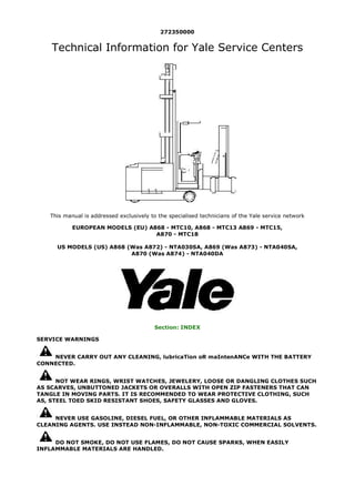
  • 1. 272350000 Technical Information for Yale Service Centers This manual is addressed exclusively to the specialised technicians of the Yale service network EUROPEAN MODELS (EU) A868 - MTC10, A868 - MTC13 A869 - MTC15, A870 - MTC18 US MODELS (US) A868 (Was A872) - NTA030SA, A869 (Was A873) - NTA040SA, A870 (Was A874) - NTA040DA Section: INDEX SERVICE WARNINGS NEVER CARRY OUT ANY CLEANING, lubricaTion oR maIntenANCe WITH THE BATTERY CONNECTED. NOT WEAR RINGS, WRIST WATCHES, JEWELERY, LOOSE OR DANGLING CLOTHES SUCH AS SCARVES, UNBUTTONED JACKETS OR OVERALLS WITH OPEN ZIP FASTENERS THAT CAN TANGLE IN MOVING PARTS. IT IS RECOMMENDED TO WEAR PROTECTIVE CLOTHING, SUCH AS, STEEL TOED SKID RESISTANT SHOES, SAFETY GLASSES AND GLOVES. NEVER USE GASOLINE, DIESEL FUEL, OR OTHER INFLAMMABLE MATERIALS AS CLEANING AGENTS. USE INSTEAD NON-INFLAMMABLE, NON-TOXIC COMMERCIAL SOLVENTS. DO NOT SMOKE, DO NOT USE FLAMES, DO NOT CAUSE SPARKS, WHEN EASILY INFLAMMABLE MATERIALS ARE HANDLED. 1/2 2018/7/6 file:///F:/1-aservicemanualpdf.com/manual/ / /YALE%20(A872)...
  • 2. In case of service outside the workshop, position the truck on a flat surface if possible and block it. If work on a slope is unavoidable, block the truck first and then move it to a level area as soon as possible. Disconnect the batteries and label all the controls to signal that service is taking place. Block the truck as well as any attachment that has to be lifted. Use only the prescribed attachment points when towing and make sure the pins and/or bolts are locked tightly before pulling. Lift and handle all heavy parts by means of a lifting device with the suitable capacity. Use the lifting eyes provided for the lifting. Do not lift over other people or permit them near a lifted load. Avoid twisting chains or wire ropes. Do not used damaged chanins or wire ropes while lifting or pulling. When handling chains or wire ropes always use goves. Handle all parts carefully. Never put your hands or fingers in between parts. Wear the special-purpose clothes, such as, safety glasses, gloves and steel toesd skid resistant shoes. The area where maintenance operations are carried out must be always kept clean and dry. Clean up any water, oi, or fuel spills immediately. Do not pile grease or oil-covered clothes. They represent a fire risk. Always put them in a closed metal container. Never carry out any service operation on the machine with anyone in the operator position, unless the operator is fully trained and involved in the operation to be carried out. Welding When welding operations are required, use appropriate protective clothing, such as, dark glasses, helmets, overalls, gioves and steel toed skid resistant shoes. Dark glasses should also be worn by anyone in the vicinity during a welding operation, even if they are not performing the work. Never look at the welding arc without properly protecting your eyes. Battery lf you have to use batteries, remember the cables shouId be connected to the terminals as specified: (+) with (+) and (-) with (-) Avoid short circuiting the (+) and (-) battery terminals together. The gas released from the batteries is highiy infiammabie. During recharging, leave the battery compartment uncovered to ensure more effective ventilation and remove the caps. DO AVOID SPARKS OR FLAMES IN THE BATTERY AREA! Never check the state of charge of the batteries using “bridges” by placing metal objects on the battery terminals. Before any service operation, check that no parts are short circuited. Eliminate short circuits before proceeding with work. Always disconnect the batteries before carrying out any electrical or mechanical service on the truck. For the battery chargers and similar equipment use only power sources having an effective earth connection to minimize the possibility of electrical shocks. Hydraulic System High pressure hydraulic fluid coming from a very small hole may be almost invisible and be sufficiently powerful enough to penetrate the skin causing serious injury. Never use your hands or any part of your body to search for hydraulic leaks. Us a piece of paper or wood to for leaks. Use the special-purpose equipment to check hydraulic system pressures. NOTE: THIS MANUAL DOES NOT REPLACE THE OWNER AND OPERATOR MANUAL. 2/2 2018/7/6 file:///F:/1-aservicemanualpdf.com/manual/ / /YALE%20(A872)...
  • 3. INDEX INTRODUCTION Section: TRUCK INSTALLATION 1.0 INTRODUCTION 1.1 VNA INSTALATION 1.2 VNA UNPACKING AND SET UP 1.3 VNA DELIVERY 2.0 VNA REMOVAL FROM CONTAINER / TRUCK 3.0 VNA STAND UP PROCEDURE 4.0 LOWER CAB AFTER STAND UP 5.0 INSTALLATION OF ATTACHMENT 6.0 ADD OIL TO HYDRAULIC TANK 7.0.A BATTERY INSTALLATION US: NTA030SA - NTA040SA EU: MTC10, MTC13, MTC15 7.0.B BATTERY INSTALLATION - US: NTA040DA EU: MTC18 8.0 INSTALLATION IN AISLE 8.1 LOAD UNIT DEPOSIT ADJUSTMENT 8.2 IMPORTANT (GUIDE ROLLERS / WIRE GUIDANCE) 9.0 OPERATOR TRAINING Section: ELECTRICAL SYSTEM ELECTRIC STEERING SYSTEM EPS-DC FOR FURTHER INFORMATION REGARDING THE ELECTRONIC SYSTEM OF THE EPS-DC ELECTRICAL STEERING SYSTEM, CONSULT SERVICE MANUAL P/N 272491100 Section: ELECTRICAL SYSTEM 1.0 ELECTRICAL COMPARTMENT ARRANGEMENT MODELS NTA030SA - NTA040SA -MTC10 - MTC13 - MTC15 1.0.1 ELECTRICAL COMPARTMENT ARRANGEMENT MODELS NTA040DA - MTC18 1.1 DESCRIPTION OF COMPONENTS 1.1.1 PHOTOCELLS 1.1.1A PHOTOCELL ADJUSTMENT 1.1.1B MALFUNCTION CAUSED BY INCORRECT ADJUSTMENT 1.1.2 THROTTLE ASSEMBLY 1.1.3 BATTERY DISCHARGE INDICATOR (BDI) 1.1.3A LOCK OUT LEVEL ADJUSTMENT 1.1.3B BDI TROUBLESHOOTING 1.1.4 DC / DC CONVERTER 1.2 TABLE OF ELECTRICAL SYSTEM COMPONENTS 2.0 TRACTION MOTOR ELECTRONIC CONTROL 2.0.1 INTRODUCTION 2.1 DEFINITION OF THE TRUCK DIRECTION OF TRAVEL 2.2 CONTROLLER GENERAL FEATURES 2.3 CONTROLLER FUNCTIONAL FEATURES 2.4 CONTROLLER DIAGNOSTICS 2.5 CHOPPER H2B MECHANICAL DIAGRAM 2.6 CONNECTORS 2.7 CONNECTOR INCONNECTOR “E” INPUT DESCRIPTION 2.9 BASIC DIAGRAM OF THE TRACTION CONTROLLER CONNECTIONS 3.0 HAND SET 3.0.1 INTRODUCTION 3.2 USE OF THE HAND SET 3.2.1 CONNECTION TO CONTROLLER 4.0 CONSOLE FUNCTION CHART - TRACTION MOTOR CONTROLLER 4.1 CONTROLLER PROGRAMMING 4.1.0 CONFIGURATION MENU 4.1.1 CONFIG. MENU / SET MODEL 4.1.2 CONFIG. MENU / SET OPTIONS 4.1.3 CONFIG. MENU / ADJUSTMENT 4.1.4 MAIN MENU / PARAMET. CHANGE 4.1.5 MAIN MENU / TESTER 4.1.6 MAIN MENU / SAVE PARAMETER 4.1.7 MAIN MENU / RESTORE PARAM 4.1.8 MAIN MENU / ALARM 4.1.9 MAIN MENU / PROGRAM VACC 4.1.9 MAIN MENU / PROGRAM VACC 1/5 2018/7/6 file:///F:/1-aservicemanualpdf.com/manual/ / /YALE%20(A872)...
  • 4. 4.2 CONFIGURATION TABLES FOR TRACTION CONTROLLER 4.3 PROGRAMMING LEVELS CORRESPONDENCE TABLE 4.4 SET UP OF A NEW CONTROLLER BEFORE OPERATION 5.0 TROUBLESHOOTING 5.1 DECODING DIAGNOSTIC LED ALARM CODES FOR TRACTION CONTROLLER 5.2 DECODING HAND SET ALARMS FOR TRACTION CONTROLLER 6.0 PUMP MOTOR CONTROLLER - DESCRIPTION 6.1 CONTROLLER FUNCTIONAL FEATURES 6.2 PUMP MOTOR CONTROLLER CIRCUIT 6.3 PUMP MOTOR CONTROLLER CONNECTORS 6.4 CONNECTOR INPUT DESCRIPTIONS (EXCEPT E) 6.5 CONNECTOR “E” INPUT DESCRIPTION 6.6.A CONSOLE FUNCTION CHART - PUMP MOTOR CONTROLLER 6.6 HAND SET PROGRAMMING OF THE PUMP MOTOR CONTROLLER 6.6.1 CONFIGURATION MENU 6.7 CONFIGURATION TABLE - PUMP MOTOR CONTROLLER 6.8 PARAMETER VALUE VERSUS PROGRAMMED LEVEL TABLE 6.14 TROUBLESHOOTING 6.14.1 DECODING DIAGNOSTIC LED ALARM CODES FOR PUMP CONTROLLER 6.14.2 DECODING HAND SET ALARMS FOR PUMP MOTOR CONTROLLER 7.0 CONFIGURATION TABLES - EPS ELECTRIC POWER STEERING CONTROLLER 7.1 EPS CONFIGURATION WITH SMART STEER (POT) STEERING 7.2 EPS CONFIGURATION WITH TACHO GENERATOR STEERING Section: PLC 1.0 STANDARD INTERLOCK FUNCTIONS 2.0 ENABLE FUNCTION MANAGEMENT 2.1 DESCRIPTION OF THE SYSTEM THAT RUNS THE ENABLES PLC (PROGRAMMABLE LOGIC CONTROLLER) 2.2 GENERAL CHARACTERISTICS 3.0 PROGRAMMING 4.0 ELECTRIC ADJUSTMENT OF THE CAB AND AUXILIARY MAST LOWERING PROPORTIONAL ELECTRO- HYDRAULIC VALVES 5.0 PLC DIGITAL INPUT / OUTPUT REFERENCE EU / US VERSIONS 5.1.A PLC TRUTH TABLE AND INTERFACE RELAY BOARD (US VERSION ONLY) 5.1.B PLC TRUTH TABLE AND INTERFACE RELAY BOARD (EU VERSION ONLY) 6.0 REMOVING/INSTALLING THE PLC 7.0 PLC BATTERY FUNCTION AND CHANGING 8.2 PROCEDURE FOR CHANGING FUSES Section: DIAGNOSTICS 1.0 CAB DOES NOT LOWER 2.0 FORKS DO NOT EXTEND LEFT 3.0 FORKS DO NOT EXTEND RIGHT 4.0 FORKS DO NOT LOWER 5.0 FORKS DO NOT RAISE 6.0 FORKS DO NOT RETRACT FROM LEFT 7.0 FORKS DO NOT RETRACT FROM RIGHT 8.0 FORKS DO NOT ROTATE LEFT 9.0 FORKS DO NOT ROTATE RIGHT 10.0 HIGH TEMPERATURE 11.0 MINI MAST DOES NOT TRAVERSE LEFT 12.0 MINI MAST DOES NOT TRAVERSE RIGHT 13.0 SYNC CAB / FORKS DO NOT LOWER 14.0 SYNC TRAVERSE / ROTATE DOES NOT WORK 15.0 TRUCK DOES NOT TRAVEL Section: SLOW DOWN / STOP 1.0 AUTOMATIC SLOW DOWN AND STOP SYSTEM DESCRIPTION 1.1 MAGNET INSTALLATION IN AISLE 1.1.1 MAGNET LAYOUT FOR SYSTEMS WITH 2 MAGNETS IN AISLE 1.1.2 MAGNET LAYOUT FOR SYSTEMS WITH 4 MAGNETS IN AISLE 2.0 SYSTEM DESCRIPTIONS 2.1 (US) END OF AISLE AUTO-BRAKING 2.2 (EU) END OF AISLE AUTO-BRAKING 2.3 SLOW DOWN / STOP (SET / RESET) 3.0 SYSTEM FUNCTIONS (WITH STANDARD PLC PROGRAM) 2/5 2018/7/6 file:///F:/1-aservicemanualpdf.com/manual/ / /YALE%20(A872)...
  • 5. 3.1 SYSTEMS WITH 2 MAGNETS IN AISLE 3.2 SYSTEMS WITH 4 MAGNETS IN AISLE 4.0 TROUBLESHOOTING Section:HYDRAULIC SYSTEM 1.0 GENERAL DESCRIPTION 1.1 HYDRAULIC SYSTEM SYMBOL LEGEND - FUNCTIONAL HYDRAULIC DIAGRAM - HYDRAULIC SYSTEM COMPONENTS 1.2 TABLE OF HYDRAULIC SYSTEM COMPONENTS 1.3 FLOW CONTROL AND HOSE BREAK VALVES 1.4 COMPONENT ACTUATION TABLE: PUMPS AND ELECTRO-SOLENOIDS 1.4.1 HYDRAULIC SYSTEM FUNCTIONAL LAYOUT 2.1 MAIN HYDRAULIC VALVE ASSEMBLY 2.1.0 MAIN HYDRAULIC VALVE ASSEMBLY COMPONENTS 2.2 CAB LIFT PRESSURE RELIEF VALVE ADJUSTMENT 2.3 ADJUSTING THE CAB LOWER PROPORTIONAL VALVE 2.3.1 EMERGENCY LOWER SCREW 2.4 TROUBLE-SHOOTING 3.1 AUXILIARY MAST/ATTACHMENT VALVE ASSEMBLY 3.1.0 AUXILIARY MAST/ATTACHMENT VALVE COMPONENT TABLE 3.2 AUXILIARY MAST/ATTACHMENT VALVE MAIN PRESSURE RELIEF ADJUSTMENT 3.3 ADJUSTING AUXILIARY MAST LOWER PROPORTIONAL VALVE 3.4 TROUBLE-SHOOTING 4.1 CAB LIFT CYLINDER EXPLODED DRAWING NTA030SA - MTC10 - MTC13 (2 STAGE MAST) 4.2 CAB LIFT CYLINDER TABLE OF COMPONENTS FOR NTA030SA - MTC10 - MTC13 5.1 CAB LIFT CYLINDER EXPLODED DRAWING NTA030SA - MTC10 - MTC13 (3 STAGE MAST) 5.2 CAB LIFT CYLINDER TABLE OF COMPONENTS FOR NTA030SA - MTC10 - MTC13 6.1 CAB LIFT CYLINDER EXPLODED DRAWING NTA040SA - NTA040DA - MTC15 - MTC18 (2 STAGE MAST) 6.2 CAB LIFT CYLINDER TABLE OF COMPONENTS FOR NTA040SA - NTA040DA - MTC15 - MTC18 7.1 CAB LIFT CYLINDER EXPLODED DRAWING NTA040SA - NTA040DA - MTC15 - MTC18 (3 STAGE MAST) 7.2 CAB LIFT CYLINDER TABLE OF COMPONENTS FOR NTA040SA - NTA040DA - MTC15 - MTC18 8.1 DISSASSEMBLING THE MAIN LIFT CYLINDERS 8.2 CHANGING THE SEALS 8.3 INSTALLING THE MAIN LIFT CYLINDERS ON THE MACHINE 8.4 BLEEDING THE AIR FROM THE MAIN HOIST CYLINDER 9.1 AUXILIARY MAST LIFT CYLINDER EXPLODED DRAWING 9.2 AUXILIARY MAST LIFT CYLINDER PART TABLE FOR 10.1 DISMANTLING AUXILIARY MAST LIFT CYLINDER 10.2 CHANGING THE SEALS 10.3 REASSEMBLING THE AUXILIARY MAST LIFT CYLINDER 10.4 BLEEDING THE AIR FROM THE AUXILIARY MAST LIFT CYLINDER Section: ATTACHMENT 1.1 ATTACHMENT COMPONENTS 1.2 ATTACHMENT COMPONENT TABLE 2.1 TRILATERAL ATTACHMENT FUNCTIONING 3.1 TRUCK INSTALLATION 3.1.1 ATTACHMENT ASSEMBLY PROCEDURES 4.1 MECHANIC ADJUSTMENT OF THE ATTACHMENT SUPPORT BEARINGS 5.1 MECHANIC STROKE END ADJUSTMENT 5.2 ROTATING MECHANIC STROKE END AND CAMS 5.3 TRASLATION SPEED REDUCER MICROSWITCH 6.1 MECHANICAL ADJUSTMENTS OF THE LOAD HANDLER BEARINGS 7.1 MAINTENANCE 8.1 TROUBLESHOOTING Section: MAST 1.0 MAST REMOVAL PROCEDURE MOD. EU MTC10 - MTC13 - MTC15 - MTC18 MOD. US NTA030SA - NTA040SA - NTA040DA 1.1 REMOVING THE CAB FROM THE MAST 2.0 REMOVING THE CYLINDERS MOD. EU MTC10 - MTC13 - MTC15 MOD. US NTA030SA - NTA040SA 2.1 REMOVING THE MAST MOD. EU MTC10 - MTC13 - MTC15 MOD. US NTA030SA - NTA040SA 3.0 REMOVING THE BOTTOM GUIDE BEARING OF THE INNER MAST SECTION MOD. EU MTC10 - MTC13 1 MOD. US NTA030SA 3/5 2018/7/6 file:///F:/1-aservicemanualpdf.com/manual/ / /YALE%20(A872)...
  • 6. 4.0 REMOVING THE ROLLERS FROM THE CAB AND INNER TELESCOPING SECTION MOD. EU MTC15 - MTC18 MOD. US NTA040SA - NTA040DA 5.0 REMOVING SIDE ROLLERS FROM THE MAST MOD. EU MTC15 - MTC18 MOD. US NTA040SA - NTA040DA Section: BILATERAL EQUIPMENT 1.0 DESCRIPTION OF EQUIPMENT 1.0.1 COMPOSITION 1.0.2 TELESCOPING ACTION 1.1 TOP TELESCOPING SECTION OR LOAD PLATFORM 1.2 INTERMEDIATE TELESCOPING SECTION 1.3 TELESCOPING SECTION SUPPORT 1.4 TELESCOPING ASSEMBLY 1.5 TABLE OF COMPONENTS 2.0 MAINTENANCE 2.0.1 HOW TO DISMANTLE THE EQUIPMENT 2.0.2 TIGHTENING TORQUES 2.0.3 PRECAUTIONS WHEN USING MAINTENANCE PRODUCTS 2.0.4 COMPONENTS REQUIRING MAINTENANCE 2.0.5 ROUTINE MAINTENANCE OPERATIONS 2.0.6 ITEMS NOT REQUIRING RELUBRICATION 2.0.7 SYMBOLS 2.0.8 FAULT-FINDING AND REMEDIES 3.0 REMOVING THE VARIOUS SECTORS 4.0 DISASSEMBLING EQUIPMENT 5.0 REMOVAL PROCEDURE Section: WHEELS 1.0 REMOVING THE LOAD WHEELS 2.0 REMOVING THE DRIVE WHEELS MOD. US - NTA030SA - NTA040SA4 EU - MTC10 (EU ONLY) - MTC13 - MTC15 3.0 REMOVING THE DRIVE WHEELS MOD. US - NTA040DA EU - MTC18 Section: BRAKING SYSTEM 1.0 BRAKING SYSTEMS DESCRIPTION 2.0 REMOVAL AND ADJUSTMENT OF THE ELECTROMAGNETIC BRAKE 3.0 ADJUSTMENT AND PUTTING INTO SERVICE Section: TRANSMISSION 1.1 DISMANTLING THE TRANSMISSION FROM THE TRUCK US - NTA030SA - NTA040SA EU - MTC10 (EU ONLY) - MTC13 - MTC15 1.2 INTRODUCTION 1.3 DISMANTLING THE CONNECTIONS 1.4 CHAIN 1.5 REMOVING THE TRANSMISSION UNIT 1.6 TRANSMISSION OIL 1.7 REMOVING THE MOTOR 1.7A REMOVING THE PLATE 1.8 DISMANTLING THE CHAIN 1.9 DISMANTLING THE WHEEL 2.0 DISMANTLING THE TRANSMISSION FROM THE TRUCK MOD. NTA040DA - MTC18 3.0 GENERAL INFORMATION NTA030SA - NTA040SA - MTC10 - MTC13 - MTC15 3.1 TRANSMISSION COMPONENTS 3.2 CONSUMABLE GOODS 3.4 STANDARD TOOLS AND FIXTURES 4.0 DISASSEMBLY 4.1 INTRODUCTION 4.2 REMOVAL AND DISASSEMBLY OF THE TRANSMISSION HOUSING UPPER PART 4.3 REMOVING OF THE TRANSMISSION COVER 4.4 DISMANTLING THE CROWN GEAR AND WHEEL SHAFT 4.5 REMOVING THE TAPER ROLLER BEARING INNER RACE FROM THE WHEEL SHAFT AND CROWN GEAR 4.6 DISASSEMBLY OF THE PINION SHAFT 4.7 DISASSEMBLY OF THE TAPER ROLLER BEARING OUTER RACE FROM THE TRANSMISSION HOUSING 4.8 REMOVING THE THREAD PROTECTIVE SHIELD 5.0 ASSEMBLY 5.1 INTRODUCTION 5.2 MEASURING THE ASSEMBLY DIMENSION OF THE PINION SHAFT 5.3 PRE-ASSEMBLY OF THE TRANSMISSION HOUSING 4/5 2018/7/6 file:///F:/1-aservicemanualpdf.com/manual/ / /YALE%20(A872)...
  • 7. 5.4 PRE-ASSEMBLY OF THE WHEEL SHAFT 5.5 MOUNTING THE TAPER ROLLER BEARING INNER RACE ON THE CROWN GEAR 5.6 PRE-ASSEMBLY OF THE PINION SHAFT 5.7 MOUNTING THE PINION SHAFT IN THE TRANSMISSION HOUSING 5.8 MEASURING THE BEARING CLEARANCE OF THE PINION SHAFT AND ADJUSTING THE PRE-STRESS 5.9 MOUNTING THE WHEEL SHAFT AND THE CROWN GEAR ON THE TRANSMISSION HOUSING 5.10 MEASURING AND ADJUSTING THE CROWN GEAR CIRCUMFERENTIAL BACKLASH 5.11 CHECKING THE TOOTH PATTERN 5.12 MEASURING THE WHEEL SHAFT BEARING CLEARANCE AND ADJUSTING THE BEARING PRE- STRESS 5.13 MOUNTING THE THREAD PROTECTIVE SHIELD IN THE TRANSMISSION HOUSING 5.14 MOUNTING THE RADIAL SHAFT SEAL IN THE TRANSMISSION HOUSING 5.15 MOUNTING THE HOUSING COVER 5.16 TRANSMISSION UPPER PART 6.0 ADJUSTMENT DATA 6.1 TIGHTENING TORQUE 7.0 TROUBLESHOOTING 8.0 STORAGE 8.1 DECOMMISSIONING 5/5 2018/7/6 file:///F:/1-aservicemanualpdf.com/manual/ / /YALE%20(A872)...
  • 8. VNA INSTALLATION 1.0 INTRODUCTION 1.1 VNA INSTALATION This section gives the field technician all information necessary to correctly install a VNA truck following the most rapid procedure.We suggest to follow the procedure step by step in the order that follows.1.0 INTRODUCTION 1.2 VNA UNPACKING AND SET UP This is the proposed method for removing a VNA Lift Truck from a hard top shipping container using a motorized hand truck and two lift trucks with adeguate lifting straps, blocks of wood 100mm x 100mm (4"X4") and cardboard to protect paintwork. This approach requires 3 people during the stand up process (2 lift truck operators and someone on the floor to coordinate). 1.3 VNA DELIVERY Typical equipment used for the installation of the VNA product: • Motorized hand pallet truck – 6000 lb (3 tonne) capacity preferred or a conventional truck with fork extensions • 8,000 lb (4 tonne) capacity forklift with 48” (1200mm) forks – used as the “rear anchor” truck during stand up process • 10,000 lb (5 tonne) (or greater) capacity forklift with 72” (1800mm) forks and at least 180" (4500mm) of lift (220 " - 5500mm of lift is required for VNA masts with overall lowered height above 195" - 4875mm) • Various lifting straps (in good condition), blocks of wood, metric Allen wrenches, standard tools, oil funnel and towels N.B. If an un-loading bay as shown in this procedure is not available or if the VNA must be lifted for other reasons from the transporter, a crane must be used with at least 19,000 lb (9 tonne) capacity. The crane will then replace the 10,000 lb (5 tonne) lift truck in the uprighting operation. 1/6 2018/7/6 file:///F:/1-aservicemanualpdf.com/manual/ / /YALE%20(A872)...
  • 9. View of VNA unit as received in the Container (Typically two are in a container depending on Mast Height) 2.0 VNA REMOVAL FROM CONTAINER / TRUCK 1. Remove palletized attachment with lift truck or motorized hand truck 2. Remove wheel chocks and tie downs that hold the VNA unit in the container 3. Move the pallet truck so as to put it up against the cross bar on the VNA support frame that it against the backrest, or use wooden spacers if the backrest cannot be put up against the cross bar. 4. Use straps or the tie downs that came with the VNA unit to affix the support frame to the crossbar between the loadwheels on the VNA truck (this keeps the support frame from deflecting forward when the VNA unit is unloaded from the container. 2/6 2018/7/6 file:///F:/1-aservicemanualpdf.com/manual/ / /YALE%20(A872)...
  • 10. 5. Slowly remove the VNA unit from the container (or unload from truck using 19.000 lb - 9 tonne crane). 6. Observe dock plate in relation to the load wheels on the VNA unit when exiting the container, also observe top of mast of the VNA unit in relation to the top of the container. 3.0 VNA STAND UP PROCEDURE 7. Check that the mechanical end stroke bolts are already fitted (they may be attached to the mast near their final position for shipment). Place lift strap around forks of lifting truck “A” (10,000 lb - 5 tonne) and through top lifting eye. Forks of lifting truck are positioned far enough from the lifting eye so that the mast when upright will not hit the forks of the lifting truck. 8. Place chain around forks of “catch truck” “B” (8,000 lb - 4 tonne) and through back lifting eye of the VNA unit. Forks of “catch truck” positioned about 5’ (1500mm) above rear of VNA unit (this provides clearance for the forks over the top of the control compartment of the VNA unit once it stands up). 9. Place cardboard “C” on back of the VNA’s control compartment doors to protect paint 3/6 2018/7/6 file:///F:/1-aservicemanualpdf.com/manual/ / /YALE%20(A872)...
  • 11. 10. A 4"X4” (100mm x 100mm) piece of wood “D” secured to the forks of the “catch truck” to prevent the strap from slipping off the forks when the VNA truck goes “over center”. Also add a securing strap to the lifting trucks strap as well. 11. Once all straps are installed, lift the unit just off the floor and remove the VNA shipping support frame “E” from the main mast. 12. Raise the mast of the lifting truck “A” (10,000 lb - 5 tonne unit) slowly while- 13. Lowering and moving the “catch truck” “B” forward – keep chains tight, do not allow chains to become slack. 14. Keep raising the forks on the lift truck to keep the VNA truck’s load wheels rolling on the ground, while keeping lifting chains tight. 4/6 2018/7/6 file:///F:/1-aservicemanualpdf.com/manual/ / /YALE%20(A872)...
  • 12. 15. When the VNA truck goes “over center” then the “catch truck” “B” will have most of the weight 16. Once the VNA truck goes “over center” then continue to drive the “catch truck” “B” forward and lower while- 17. Slowly lowering the forks on the lifting truck “A” until the VNA unit is standing. 4.0 LOWER CAB AFTER STAND UP 5/6 2018/7/6 file:///F:/1-aservicemanualpdf.com/manual/ / /YALE%20(A872)...
  • 13. Fig (13) 18. Make sure the hoses, cables and hoist chains will not become snagged or damaged in the VNA’s mast when lowering the cab. 19. Support the cab with the “catch truck” 20. Keep hands and body clear of mast and cab while cutting steel straps (if equipped) that hold the cab of the VNA. 21. Open the manual lowering valve located in the control compartment (in the rear) of the VNA unit. 22. Lower the cab to the ground. 6/6 2018/7/6 file:///F:/1-aservicemanualpdf.com/manual/ / /YALE%20(A872)...
  • 14. Thank you very much for your reading. Please Click Here. Then Get COMPLETE MANUAL. NO WAITING NOTE: If there is no response to click on the link above, please download the PDF document first and then click on it.
  • 15. 5.0 INSTALLATION OF ATTACHMENT 23. Pick up the attachment from the loading skid so that it hangs level (X,Y and Z axis) from the forks of the 8,000 lb (4 tonne) lift truck. 24. Use 6” X 6” X 24” (150mm X 150mm X 600mm) blocks of wood on top of forks to wrap the lift straps around. 25. Remove stop plate from lower traverse rail so attachment can be slid on. 26. Remove the traverse motor from the attachment so that the upper and lower gears on the attachment spin freely. 27. Orientate the plastic support block (bushing) on the attachment so that the large opening is to the side. 1/6 2018/7/6 file:///F:/1-aservicemanualpdf.com/manual/ / /YALE%20(A872)...
  • 16. Note the attachment sits 90 degrees to the traverse rail 28. Install attachment onto VNA truck, be sure the upper and lower gears on the attachment go into the traverse rail at the same time or the attachment will bind. (if the 8,000 lb - 4 tonne unit is equipped with a sideshift, this makes the process easier). Pay attention to insert the bearing with scraper orientated correctly (narrow window top and bottom ) - see fig (19). 29. If the attachment is installed correctly, it should easily move side to side effortlessly (can push by hand). 30. Once the attachment is installed be sure to re-install the traverse stop plate onto the traverse rail before unchaining attachment from the 8,000 lb (4 tonne) unit. 31. Re-install the traverse motor. 2/6 2018/7/6 file:///F:/1-aservicemanualpdf.com/manual/ / /YALE%20(A872)...
  • 17. Look how to position the rounded cable (US and Cold Store Version) Look how to position the flat cable (EU standard Version) 32. Route hydraulic lines and wiring into attachment (this is critical, do as the picture shows to prevent interference with the movable shaft that connects the top gear of the traverse mechanism with the lower gear). 33. Connect plastic drag link chain into metal brackets. 34. Install hydraulic lines to attachment valve (the fittings are standard JIC). 35. Hook up wiring (VNA unit may have unused wiring for options not installed on the truck). Electrical connectors are labeled with stickers (N, P, U and Q). Match up connectors from main harness to attachment harness using these labels. 3/6 2018/7/6 file:///F:/1-aservicemanualpdf.com/manual/ / /YALE%20(A872)...