
Recommended
Recommended
More Related Content
What's hot
What's hot (11)
Similar to Yale c875 gtp25 vxp lift truck service repair manual
Similar to Yale c875 gtp25 vxp lift truck service repair manual (12)
More from fjskkmemem
More from fjskkmemem (20)
Recently uploaded
Recently uploaded (20)
Yale c875 gtp25 vxp lift truck service repair manual
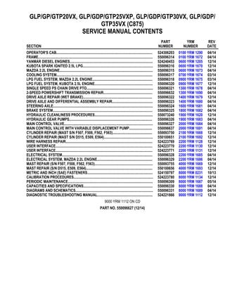
- 1. GLP/GP/GTP20VX, GLP/GDP/GTP25VXP, GLP/GDP/GTP30VX, GLP/GDP/ GTP35VX (C875) SERVICE MANUAL CONTENTS SECTION PART NUMBER YRM NUMBER REV DATE OPERATOR'S CAB........................................................................................................ 524306203 0100 YRM 1290 04/14 FRAME............................................................................................................................ 550096314 0100 YRM 1672 04/14 YANMAR DIESEL ENGINES.......................................................................................... 524240453 0600 YRM 1205 12/14 KUBOTA SPARK IGNITED 2.5L LPG............................................................................ 550096316 0600 YRM 1670 12/14 MAZDA 2.2L ENGINE..................................................................................................... 550096315 0600 YRM 1673 04/14 COOLING SYSTEM........................................................................................................ 550096317 0700 YRM 1674 03/14 LPG FUEL SYSTEM, MAZDA 2.2L ENGINE................................................................. 550096318 0900 YRM 1675 03/14 LPG FUEL SYSTEM, KUBOTA 2.5L ENGINE............................................................... 550096320 0900 YRM 1677 12/14 SINGLE SPEED PS CHAIN DRIVE PTO........................................................................ 550096321 1300 YRM 1678 04/14 2-SPEED POWERSHIFT TRANSMISSION REPAIR..................................................... 550096632 1300 YRM 1690 04/14 DRIVE AXLE REPAIR (WET BRAKE)........................................................................... 550096322 1400 YRM 1679 12/14 DRIVE AXLE AND DIFFERENTIAL ASSEMBLY REPAIR............................................ 550096323 1400 YRM 1680 04/14 STEERING AXLE............................................................................................................ 550096324 1600 YRM 1681 04/14 BRAKE SYSTEM............................................................................................................ 550096325 1800 YRM 1682 04/14 HYDRAULIC CLEANLINESS PROCEDURES............................................................... 550073240 1900 YRM 1620 12/14 HYDRAULIC GEAR PUMPS.......................................................................................... 550096326 1900 YRM 1683 04/14 MAIN CONTROL VALVE................................................................................................ 550096327 2000 YRM 1684 04/14 MAIN CONTROL VALVE WITH VARIABLE DISPLACEMENT PUMP......................... 550096637 2000 YRM 1691 04/14 CYLINDER REPAIR (MAST S/N F507, F508, F562, F563)........................................... 550093750 2100 YRM 1668 12/14 CYLINDER REPAIR (MAST S/N D515, E509, E564)..................................................... 550100651 2100 YRM 1692 12/14 WIRE HARNESS REPAIR.............................................................................................. 524223769 2200 YRM 1128 12/14 USER INTERFACE......................................................................................................... 524223770 2200 YRM 1130 12/14 USER INTERFACE......................................................................................................... 524223771 2200 YRM 1131 12/14 ELECTRICAL SYSTEM.................................................................................................. 550096328 2200 YRM 1685 04/14 ELECTRICAL SYSTEM, MAZDA 2.2L ENGINE............................................................ 550096329 2200 YRM 1686 04/14 MAST REPAIR (S/N F507, F508, F562, F563)............................................................... 550093755 4000 YRM 1669 12/14 MAST REPAIR (S/N D515, E509, E564)........................................................................ 550100656 4000 YRM 1693 12/14 METRIC AND INCH (SAE) FASTENERS....................................................................... 524150797 8000 YRM 0231 10/13 CALIBRATION PROCEDURES...................................................................................... 524223780 8000 YRM 1134 12/14 PERIODIC MAINTENANCE............................................................................................ 550096309 8000 YRM 1687 05/14 CAPACITIES AND SPECIFICATIONS........................................................................... 550096330 8000 YRM 1688 04/14 DIAGRAMS AND SCHEMATICS.................................................................................... 550096331 8000 YRM 1689 04/14 DIAGNOSTIC TROUBLESHOOTING MANUAL............................................................ 524221866 9000 YRM 1112 12/14 9000 YRM 1112 ON CD PART NO. 550096627 (12/14)
- 2. General The overhead guard is an integral part of operator cab. The operator cab is installed on a platform above main frame members. Step plates on both sides of lift truck provide access to operator cab. The operator cab is a separate unit and can be removed as a complete unit from module and frame of the lift truck. See Figure 1. Figure 1. Operator Cab 0100 YRM 1290 General 1
- 3. Cab Replacement REMOVE, FOR LIFT TRUCK MODELS GLP/GDP16VX, GLP/GDP18VX, GLP/ GDP20SVX, GLP/GDP030VX (C810); GLP/ GDP20-35VX (GP/GLP/GDP040-070VX) (B875, C875); AND GLP/GDP40VX5/VX6, GLP/GDP45SVX5, GLP/GDP45VX6, GLP/ GDP50-55VX (GP/GLP/GDP080, 090, 100, 110, 120VX) (F813, G813, H813, J813) NOTE: The EZ Tank Bracket used on these trucks to mount LPG tank onto counterweight come in two styles. One style of bracket swings out to side of truck and other swings out to side and drops down. NOTE: On lift trucks equipped with LPG, make sure to release EZ Tank Bracket before opening hood. 1. For lift truck models GLP/GDP16VX, GLP/ GDP18VX, GLP/GDP20SVX, GLP/GDP030VX (C810), tilt steering column to UP position, slide seat assembly forward, open rear door, and open hood to disconnect battery. See Figure 2. 2. Tilt steering column to UP position, slide seat as- sembly forward, open rear sliding window, and open hood to disconnect battery. See Figure 3 for lift truck models • GLP/GDP20-35VX (GP/GLP/ GDP040-070VX) (B875, C875) • GLP/GDP40VX5/VX6; GLP/GDP45SVX5, GLP/GDP45VX6; GLP/GDP50-55VX (GP/GLP/GDP080, 090, 100, 110, 120VX) (F813, G813, H813, J813) 3. Disconnect air filter hose from rear left corner leg of cab frame. See Figure 4. WARNING DO NOT disconnect the heater hoses from the en- gine when the engine is hot or when the cooling system is under pressure, to do so could cause serious injury. WARNING DO NOT remove the radiator cap from the radiator when the engine is hot. When the radiator is hot and the cap is removed, the pressure is released from the system and the steam and boiling cool- ant can cause burns. Wait 30 minutes for the en- gine to cool. Do a touch test by touching the radi- ator with your hand. If the radiator is still hot to the touch, wait another 30 minutes before at- tempting to remove, check, or fix any part of the cooling system. NOTE: Removing radiator cap will help depressurize cooling system. 4. Remove radiator cover to access radiator cap. Remove radiator cap. See Figure 5. 1. LATCH 2. HINGE 3. REAR DOOR Figure 2. Rear Door and Latch for Lift Truck Models GLP/GDP16VX, GLP/GDP18VX, GLP/ GDP20SVX, GLP/GDP030VX (C810) Cab Replacement 0100 YRM 1290 2
- 4. A. LIFT TRUCKS MODELS GLP/GDP20-35VX (GP/GLP/GDP040-070VX) (B875, C875) AND GLP/GDP40VX5/ VX6, GLP/GDP45SVX5, GLP/GDP45VX6, GLP/GDP50-55VX (GP/GLP/GDP080, 090, 100, 110, 120VX) (F813, G813, H813, J813) WITHOUT AIR CONDITIONING. B. LIFT TRUCKS MODELS GLP/GDP40VX5/VX6, GLP/GDP45SVX5, GLP/GDP45VX6, GLP/GDP50-55VX (GP/GLP/GDP080, 090, 100, 110, 120VX) (G813, H813, J813) WITH AIR CONDITIONING. 1. REAR BOTTOM WINDOW 2. RELEASE LATCH 3. AC HOSE Figure 3. Rear Bottom Window for Lift Trucks Models GLP/GDP20-35VX (GP/GLP/GDP040-070VX) (B875, C875) and GLP/GDP40VX5/VX6, GLP/GDP45SVX5, GLP/GDP45VX6, GLP/GDP50-55VX (GP/GLP/GDP080, 090, 100, 110, 120VX) (F813, G813, H813, J813) Figure 4. Air Filter Hose Removal Legend for Figure 4 NOTE: AIR FILTER HOSE FOR GLP/GDP40VX5/ VX6, GLP/GDP45SVX5, GLP/GDP45VX6, GLP/ GDP50-55VX (GP/GLP/GDP080, 090, 100, 110, 120VX) (F813) SHOWN. AIR FILTER HOSE FOR OTHER LIFT TRUCK MODELS ARE SIMILAR. 1. CAPSCREW 2. AIR FILTER HOSE 0100 YRM 1290 Cab Replacement 3
- 5. A. GLP/GDP16VX, GLP/GDP18VX, GLP/GDP20SVX, GLP/GDP030VX (C810) B. GLP/GDP20-35VX (GP/GLP/GDP040-070VX) (B875, C875) C. GLP/GDP40VX5/VX6; GLP/GDP45SVX5, GLP/GDP45VX6; GLP/GDP50-55VX (GP/GLP/GDP080, 090, 100, 110, 120VX) (F813, G813, H813) D. GLP/GDP40VX5/VX6; GLP/GDP45SVX5, GLP/GDP45VX6; GLP/GDP50-55VX (GP/GLP/GDP080, 090, 100, 110, 120VX) (J813) 1. RADIATOR COVER 2. RADIATOR CAP Figure 5. Radiator Cover and Cap Location Cab Replacement 0100 YRM 1290 4
- 6. CAUTION DO NOT allow any fluid to drain when disconnect- ing the heater hose from the engine. The method will help when purging the system during installa- tion. 5. Disconnect and cap heater hoses from engine. See Figure 6. WARNING Replacement, installation and repairs to air condi- tioning units that require discharging and/or refill- ing of the refrigeration fluid must be performed by a certified technician. 6. Contact a certified air conditioning specialist to have the refrigerant extracted from the air condi- tioning system. NOTE: Step 7 is for lift truck models GLP/ GDP40VX5/VX6; GLP/GDP45SVX5, GLP/ GDP45VX6; GLP/GDP50-55VX (GP/GLP/GDP080, 090, 100, 110, 120VX) (G813, H813, J813) with a Cummins QSB 3.3L or a Kubota diesel engine. 7. If lift truck cab is equipped with an air conditioner/ heater unit, disconnect AC refrigerant hoses from refrigerant compressor. See Figure 7 for lift truck models • GLP/GDP40VX5/VX6; GLP/GDP45SVX5, GLP/GDP45VX6; GLP/GDP50-55VX (GP/GLP/GDP080, 090, 100, 110, 120VX) (G813) See Figure 8 for lift truck models • GLP/GDP40VX5/VX6; GLP/GDP45SVX5, GLP/GDP45VX6; GLP/GDP50-55VX (GP/GLP/GDP080, 090, 100, 110, 120VX) (H813, J813) NOTE: Removing door assemblies requires two peo- ple. 8. Open left side door, remove lock nut, and discon- nect gas spring from cab mounting bracket. See Figure 9. 9. Lift left side door up and over hinge pin and set aside. See Figure 10. WARNING DO NOT disconnect the heater hoses from the quick disconnect fittings (inside operator cab) or engine when the engine is hot or under pressure, to do so could cause serious injury. 10. Disconnect heater hose quick disconnect fittings. a. For lift truck models GLP/GDP16VX, GLP/ GDP18VX, GLP/GDP20SVX, GLP/GDP030VX (C810), open right side door and push buttons on quick disconnect fittings to disconnect heater hoses from heater assembly hoses (see Figure 6). Disconnect heater wire harness con- nection. See Figure 11. b. For lift truck models GLP/GDP20-35VX (GP/GLP/GDP040-070VX) (B875, C875), open right side door and remove radiator cover to access quick disconnect fittings. Push buttons on quick disconnect fittings to disconnect heater hoses from heater assembly (see Fig- ure 6). Disconnect heater wire harness con- nection. See Figure 11. c. For lift truck models GLP/GDP40VX5/VX6; GLP/GDP45SVX5, GLP/GDP45VX6; GLP/ GDP50-55VX (GP/GLP/GDP080, 090, 100, 110, 120VX) (F813, G813, H813, J813), open right side door and located on inner rear cover there are two port holes (see Figure 6). Push buttons on quick disconnect fittings to discon- nect heater hoses from heater assembly and disconnect heater wire harness connection. See Figure 11. 0100 YRM 1290 Cab Replacement 5
- 7. Figure 6. Heater Hose Connection Cab Replacement 0100 YRM 1290 6
- 8. Legend for Figure 6 NOTE: ART SHOWN MAY NOT REFLECT ENGINE IN LIFT TRUCK. NOTE: MAJOR COMPONENTS OF CAB HAVE BEEN REMOVED FOR CLARITY. A. LIFT TRUCK MODELS GLP/GDP16VX, GLP/ GDP18VX, GLP/GDP20SVX, GLP/GDP030VX (C810) B. LIFT TRUCK MODELS GLP/GDP20-35VX (GP/GLP/GDP040-070VX) (B875, C875) C. LIFT TRUCK MODELS GLP/GDP20-35VX (GP/GLP/GDP040-070VX) (B875, C875) D. LIFT TRUCK MODELS GLP/GDP40VX5/VX6; GLP/GDP45SVX5, GLP/GDP45VX6; GLP/ GDP50-55VX (GP/GLP/GDP080, 090, 100, 110, 120VX) (F813, G813) E. LIFT TRUCK MODELS GLP/GDP40VX5/VX6; GLP/GDP45SVX5, GLP/GDP45VX6; GLP/ GDP50-55VX (GP/GLP/GDP080, 090, 100, 110, 120VX) (H813, J813) 1. QUICK DISCONNECT FITTING 2. INNER REAR COVER 3. RADIATOR COVER 4. RIGHT SIDE DOOR ASSEMBLY 5. HEATER HOSES 0100 YRM 1290 Cab Replacement 7
- 9. NOTE: MAJOR COMPONENTS OF CAB HAVE BEEN REMOVED FOR CLARITY. 1. HOSE FITTING 2. REFRIGERANT COMPRESSOR 3. AC/HEATER UNIT 4. ENGINE Figure 7. AC Refrigerant Hose Connections, Lift Truck Models GLP/GDP40VX5/VX6; GLP/GDP45SVX5, GLP/GDP45VX6; GLP/GDP50-55VX (GP/GLP/GDP080, 090, 100, 110, 120VX) (G813) with Cummins QSB 3.3L Engine Cab Replacement 0100 YRM 1290 8
- 10. NOTE: MAJOR COMPONENTS OF CAB HAVE BEEN REMOVED FOR CLARITY. KUBOTA 3.8L DIESEL EN- GINE SHOWN, 3.6L DIESEL ENGINE SIMILAR. A. LIFT TRUCK MODELS GLP/GDP40VX5/VX6; GLP/GDP45SVX5, GLP/GDP45VX6; GLP/GDP50-55VX (GP/GLP/GDP080, 090, 100, 110, 120VX) (H813) B. LIFT TRUCK MODELS GLP/GDP40VX5/VX6; GLP/GDP45SVX5, GLP/GDP45VX6; GLP/GDP50-55VX (GP/GLP/GDP080, 090, 100, 110, 120VX) (J813) 1. HOSE FITTING 2. REFRIGERANT COMPRESSOR 3. AC/HEATER UNIT 4. ENGINE Figure 8. AC Refrigerant Hose Connection, Lift Truck Models GLP/GDP40VX5/VX6; GLP/GDP45SVX5, GLP/GDP45VX6; GLP/GDP50-55VX (GP/GLP/GDP080, 090, 100, 110, 120VX) (H813, J813) with Kubota Diesel Engine 0100 YRM 1290 Cab Replacement 9
- 11. NOTE: RIGHT SIDE DOOR SHOWN. 1. GAS SPRING 2. CAB MOUNTING BRACKET 3. LOCK NUT Figure 9. Gas Spring Mounting Removal Figure 10. Door Removal Legend for Figure 10 NOTE: RIGHT SIDE DOOR HINGE SHOWN. 1. HINGE PIN 2. DOOR HINGE NOTE: MAJOR COMPONENTS OF CAB HAVE BEEN REMOVED FOR CLARITY. 1. HEATER WIRE HARNESS CONNECTOR 2. REAR GRAB HANDLE HORN BUTTON CON- NECTOR (TO RIGHT-HAND CHASSIS HAR- NESS) Figure 11. Heater Wire Harness and Rear Grab Handle Horn Button Connectors Cab Replacement 0100 YRM 1290 10
- 12. 11. For lift truck models GLP/GDP40VX5/VX6; GLP/ GDP45SVX5, GLP/GDP45VX6; GLP/ GDP50-55VX (GP/GLP/GDP080, 090, 100, 110, 120VX) (G813, H813, J813) with a Cummins QSB 3.3L or Kubota diesel engine, if lift truck cab is equipped with an air conditioner/heater unit, dis- connect AC hoses. a. Remove six fasteners and remove rear cover. See Figure 12 for lift truck models • GLP/GDP40VX5/VX6; GLP/GDP45SVX5, GLP/GDP45VX6; GLP/GDP50-55VX (GP/GLP/GDP080, 090, 100, 110, 120VX) (G813) See Figure 13 for lift truck models • GLP/GDP40VX5/VX6; GLP/GDP45SVX5, GLP/GDP45VX6; GLP/GDP50-55VX (GP/GLP/GDP080, 090, 100, 110, 120VX) (H813) See Figure 14 for lift truck models • GLP/GDP40VX5/VX6; GLP/GDP45SVX5, GLP/GDP45VX6; GLP/GDP50-55VX (GP/GLP/GDP080, 090, 100, 110, 120VX) (J813) b. Disconnect air conditioner hoses at bulkhead bracket and at receiver/drier. See Figure 12 for lift truck models • GLP/GDP40VX5/VX6; GLP/GDP45SVX5, GLP/GDP45VX6; GLP/GDP50-55VX (GP/GLP/GDP080, 090, 100, 110, 120VX) (G813) See Figure 13 for lift truck models • GLP/GDP40VX5/VX6; GLP/GDP45SVX5, GLP/GDP45VX6; GLP/GDP50-55VX (GP/GLP/GDP080, 090, 100, 110, 120VX) (H813) See Figure 14 for lift truck models • GLP/GDP40VX5/VX6; GLP/GDP45SVX5, GLP/GDP45VX6; GLP/GDP50-55VX (GP/GLP/GDP080, 090, 100, 110, 120VX) (J813) c. Disconnect air conditioner wire harness. See Figure 12 for lift truck models • GLP/GDP40VX5/VX6; GLP/GDP45SVX5, GLP/GDP45VX6; GLP/GDP50-55VX (GP/GLP/GDP080, 090, 100, 110, 120VX) (G813) See Figure 13 for lift truck models • GLP/GDP40VX5/VX6; GLP/GDP45SVX5, GLP/GDP45VX6; GLP/GDP50-55VX (GP/GLP/GDP080, 090, 100, 110, 120VX) (H813) See Figure 14 for lift truck models • GLP/GDP40VX5/VX6; GLP/GDP45SVX5, GLP/GDP45VX6; GLP/GDP50-55VX (GP/GLP/GDP080, 090, 100, 110, 120VX) (J813) 12. Remove lock nut and disconnect gas spring from cab mounting bracket. See Figure 9. 13. Lift door up and over hinge pin and set aside. See Figure 10. NOTE: Wiper motor cover must be removed before dash assembly can be removed. 14. Unclip and remove front wiper motor cover. See Figure 15 for lift truck models • GLP/GDP16VX, GLP/GDP18VX, GLP/ GDP20SVX, GLP/GDP030VX (C810) • GLP/GDP20-35VX (GP/GLP/ GDP040-070VX) (B875, C875) 0100 YRM 1290 Cab Replacement 11
- 13. Thank you very much for your reading. Please Click Here. Then Get COMPLETE MANUAL. NO WAITING NOTE: If there is no response to click on the link above, please download the PDF document first and then click on it.
- 14. NOTE: MAJOR COMPONENTS OF CAB HAVE BEEN REMOVED FOR CLARITY. A. FRONT VIEW B. TOP VIEW 1. HOSE WRAP 2. FASTENERS 3. REAR COVER 4. AIR CONDITIONER HOSES 5. BULKHEAD BRACKET 6. RECEIVER/DRIER 7. FITTINGS 8. AIR CONDITIONER WIRE HARNESS Figure 12. AC System Arrangement and Hose Connections, Lift Truck Models GLP/GDP40VX5/VX6; GLP/ GDP45SVX5, GLP/GDP45VX6; GLP/GDP50-55VX (GP/GLP/GDP080, 090, 100, 110, 120VX) (G813) With a Cummins QSB 3.3L Diesel Engine Cab Replacement 0100 YRM 1290 12
- 15. NOTE: MAJOR COMPONENTS OF CAB HAVE BEEN REMOVED FOR CLARITY. A. FRONT VIEW B. TOP VIEW 1. HOSE WRAP 2. FASTENERS 3. REAR COVER 4. AIR CONDITIONER HOSES 5. BULKHEAD BRACKET 6. RECEIVER/DRIER 7. FITTINGS 8. AIR CONDITIONER WIRE HARNESS Figure 13. AC System Arrangement and Hose Connections, Lift Truck Models GLP/GDP40VX5/VX6; GLP/ GDP45SVX5, GLP/GDP45VX6; GLP/GDP50-55VX (GP/GLP/GDP080, 090, 100, 110, 120VX) (H813) With a Kubota Diesel Engine 0100 YRM 1290 Cab Replacement 13
- 16. NOTE: MAJOR COMPONENTS OF CAB HAVE BEEN REMOVED FOR CLARITY. A. FRONT VIEW B. TOP VIEW 1. HOSE WRAP 2. FASTENERS 3. REAR COVER 4. AIR CONDITIONER HOSES 5. BULKHEAD BRACKET 6. RECEIVER/DRIER 7. FITTINGS 8. AIR CONDITIONER WIRE HARNESS Figure 14. AC System Arrangement and Hose Connections, Lift Truck Models GLP/GDP40VX5/VX6; GLP/ GDP45SVX5, GLP/GDP45VX6; GLP/GDP50-55VX (GP/GLP/GDP080, 090, 100, 110, 120VX) (J813) With a Kubota Diesel Engine Cab Replacement 0100 YRM 1290 14
- 17. Figure 15. Dash Installation 0100 YRM 1290 Cab Replacement 15
- 18. Legend for Figure 15 NOTE: MAJOR COMPONENTS OF CAB HAVE BEEN REMOVED FOR CLARITY. A. GLP/GDP16VX, GLP/GDP18VX, GLP/GDP20SVX (GP/GLP/GDP030VX, GP/GLP/GDP035VX, GP/GLP/ GDP040SVX) (C810) AND GLP/GDP20-35VX (GP/GLP/GDP040-070VX) (B875, C875) B. GLP/GDP40VX5/VX6; GLP/GDP45SVX5, GLP/GDP45VX6; GLP/GDP50-55VX (GP/GLP/GDP080, 090, 100, 110, 120VX) (F813, G813, H813, J813) 1. CAPSCREWS 2. FRONT WIPER MOTOR COVER 3. DASH ASSEMBLY 4. KICK PANEL 5. COWL PANEL 6. FRONT OPERATOR CAB LEGS 7. LOCK NUT 8. FLANGE BOLT 15. For lift truck models GLP/GDP40VX5/VX6; GLP/ GDP45SVX5, GLP/GDP45VX6; GLP/ GDP50-55VX (GP/GLP/GDP080, 090, 100, 110, 120VX) (F813, G813), remove two lock nuts from front wiper motor cover. Remove front wiper mo- tor cover. See Figure 15. 16. For lift truck models GLP/GDP40VX5/VX6; GLP/ GDP45SVX5, GLP/GDP45VX6; GLP/ GDP50-55VX (GP/GLP/GDP080, 090, 100, 110, 120VX) (H813, J813), remove three lock nuts from front wiper motor cover. Remove front wiper motor cover. 17. Remove five capscrews from top of dash assem- bly and cowl panel. 18. Remove two flange bolts securing cowl panel to front operator cab legs. 19. Unclip dash assembly from kick panel. Remove dash assembly. 20. Remove kick panel from seal plate assembly. See Figure 16. Cab Replacement 0100 YRM 1290 16
- 19. Figure 16. Seal Plate Assembly, Kick Panel, and Floor Plate Removal 0100 YRM 1290 Cab Replacement 17