
Recommended
Recommended
More Related Content
Similar to Yale a974 gdp20 lx lift truck service repair manual
Similar to Yale a974 gdp20 lx lift truck service repair manual (19)
More from fjsjjdkemmde
More from fjsjjdkemmde (20)
Recently uploaded
Recently uploaded (20)
Yale a974 gdp20 lx lift truck service repair manual
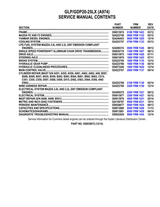
- 1. GLP/GDP20-25LX (A974) SERVICE MANUAL CONTENTS SECTION PART NUMBER YRM NUMBER REV DATE FRAME............................................................................................................................ 550013974 0100 YRM 1423 03/12 MAZDA FE AND F2 ENGINES....................................................................................... 524223756 0600 YRM 1122 03/12 YANMAR DIESEL ENGINES.......................................................................................... 524240453 0600 YRM 1205 12/14 COOLING SYSTEM........................................................................................................ 524223757 0700 YRM 1123 03/13 LPG FUEL SYSTEM MAZDA 2.0L AND 2.2L 2007 EMISSION COMPLIANT ENGINES.................................................................................................................... 524289374 0900 YRM 1326 09/12 SINGLE SPEED POWERSHIFT ALUMINUM CHAIN DRIVE TRANSMISSION............ 550030170 1300 YRM 1447 08/13 DRIVE AXLE................................................................................................................... 550013975 1400 YRM 1426 07/11 STEERING AXLE............................................................................................................ 550013976 1600 YRM 1425 07/11 BRAKE SYSTEM............................................................................................................ 524223765 1800 YRM 1135 12/12 HYDRAULIC GEAR PUMP............................................................................................. 524223766 1900 YRM 1136 04/14 HYDRAULIC CLEANLINESS PROCEDURES............................................................... 550073240 1900 YRM 1620 12/14 MAIN CONTROL VALVE................................................................................................ 524223767 2000 YRM 1137 04/14 CYLINDER REPAIR (MAST S/N A551, A555, A559, A661, A662, A663, A66, B507, B508, B509, B551, B555, B559, B562, B563, B564, B661, B662, B663, C515, C551, C555, C559, D507, D508, D509, D515, D562, D563, D564, E509, AND E564).......................................................................................................................... 524223768 2100 YRM 1139 02/14 WIRE HARNESS REPAIR.............................................................................................. 524223769 2200 YRM 1128 12/14 ELECTRICAL SYSTEM MAZDA 2.0L AND 2.2L 2007 EMISSION COMPLIANT ENGINES.................................................................................................................... 524289375 2200 YRM 1327 09/12 ELECTRICAL SYSTEM.................................................................................................. 550013977 2200 YRM 1427 03/12 MAST REPAIR (S/N A698, A699, B551)........................................................................ 550013978 4000 YRM 1431 02/14 METRIC AND INCH (SAE) FASTENERS....................................................................... 524150797 8000 YRM 0231 10/13 PERIODIC MAINTENANCE............................................................................................ 550038077 8000 YRM 1424 08/13 CAPACITIES AND SPECIFICATIONS........................................................................... 550013980 8000 YRM 1428 11/13 SCHEMATICS/DIAGRAMS............................................................................................ 550013981 8000 YRM 1429 04/14 DIAGNOSTIC TROUBLESHOOTING MANUAL............................................................ 550022929 9000 YRM 1434 12/14 Service information for Cummins diesel engines can be ordered through the Hyster Literature Distribution Center. PART NO. 550038072 (12/14)
- 2. 100 YRM 1423 General General WARNING The lift truck must be put on blocks for some types of maintenance and repairs. The removal of the following assemblies will cause large changes in the center of gravity: mast, drive axle, engine and transmission, and counterweight. When the lift truck is put on blocks, put additional blocks in the following positions to maintain stability: • Before removing the mast and drive axle, put blocks under the counterweight so the lift truck cannot fall backward. • Before removing the counterweight, put blocks under the mast assembly so the lift truck cannot fall forward. The surface must be solid, even, and level when the lift truck is put on blocks. Make sure that any blocks used to support the lift truck are solid, one-piece units. See the Operating Manual or the section Pe- riodic Maintenance 8000 YRM 1424. This section contains the description of the frame (see Figure 1) and connected parts. Procedures for remov- ing and installing the counterweight, hood, overhead guard, engine, and cooling system are found in this sec- tion. Checks for the operator restraint system, adjust- ments for the throttle pedal stop, and procedures for the repair of tanks and installation of safety labels are also included. 1. COWL PLATE 2. FENDER 3. FRAME 4. HOOD MOUNT 5. COUNTERWEIGHT SUPPORT 6. LEFT-HAND FRAME WELDMENT 7. HYDRAULIC TANK Figure 1. Frame 1
- 3. Hood, Seat, and Side Covers Replacement 100 YRM 1423 Hood, Seat, and Side Covers Replacement REMOVE 1. Slide the seat to the closest position to the steering column. 2. Fully tilt the steering column forward. NOTE: Perform Step 3 for lift trucks equipped with LPG. 3. Swing LPG tank off to side. See LPG Fuel System, Mazda FE and F2 Emission Compliant Engines 900 YRM 1326 for procedures. 4. Raise the hood latch on the left, front corner of the hood to unlatch and lift up the hood. See Figure 2. 5. Remove the floor mat and floor plate. See Figure 3. 6. Remove the two capscrews holding the left and right rear side covers to the frame. Remove the rear side covers from the frame. See Figure 3. 7. Remove the four capscrews and clip nuts holding the left and right front side covers and left and right cowl plates to the frame. Remove front side covers and cowl plates. 8. Fully lower the steering column. 1. HOOD LATCH 2. SEAT 3. HOOD Figure 2. Hood Latch Legend for Figure 3 1. DASH ASSEMBLY 2. UPPER STEERING COLUMN COVER 3. LOWER STEERING COLUMN COVER 4. KICK PANEL 5. PLATE ASSEMBLY 6. GROMMET 7. LEFT FRONT SIDE COVER 8. RIGHT FRONT SIDE COVER 9. LEFT STEP PANEL 10. RIGHT STEP PANEL 11. LEFT STEP PLATE 12. RIGHT STEP PLATE 13. LEFT REAR SIDE COVER 14. RIGHT REAR SIDE COVER 15. FLOOR MAT 16. FLOOR PLATE 17. RADIATOR COVER 18. SEALS 19. CAPSCREW 20. CLIP NUT 21. INSERT 22. PLATE ASSEMBLY SEAL 23. LEFT COWL PLATE 24. RIGHT COWL PLATE 2
- 4. 100 YRM 1423 Hood, Seat, and Side Covers Replacement Figure 3. Side Cover, Floor Plate, and Cowl Components 3
- 5. Hood, Seat, and Side Covers Replacement 100 YRM 1423 9. Remove upper steering column cover by pulling up on the base of the upper steering column cover to release the latches (one on either side), and pulling cover away from steering column. See Figure 4. 10. Remove the five Allen Head screws (see Figure 4) securing the dash to top of cowl. 11. Pull kick panel up from bottom and out to remove kick panel from seal plate and clips on dash panel. 12. Remove dash panel from cowl. See Figure 5. 13. Remove three capscrews holding the seal plate. Remove seal plate. See Figure 5. NOTE: TOP VIEW OF DASH PANEL SHOWN A. INDICATES TO PULL UP TO UNLATCH 1. ALLEN HEAD SCREWS 2. COWL 3. UPPER STEERING COLUMN COVER 4. LOWER STEERING COLUMN COVER Figure 4. Dash Panel and Upper Steering Column Cover Removal 4
- 6. 100 YRM 1423 Hood, Seat, and Side Covers Replacement 1. ALLEN HEAD SCREWS 2. COWL 3. DASH PANEL 4. KICK PANEL 5. KICK PANEL NOTCHES 6. SEAL PLATE 7. CAPSCREWS 8. CLIPS Figure 5. Dash Panel, Kick Panel, and Seal Plate Removal 5
- 7. Hood, Seat, and Side Covers Replacement 100 YRM 1423 14. Remove two capscrews and washers from cover plate and remove electrical cover. Disconnect seat harness from chassis harness. See Figure 6. CAUTION When removing the seat from the hood, do not use an impact wrench to remove the capscrews. Dam- age can be caused to the threads on the capscrews and in the holes. 15. Open hood and pull chassis harness through hole in hood. See Figure 7. Remove the four capscrews and nuts holding the seat to the hood. Lift the seat off the hood. See Figure 7. Close hood. 16. Remove the nuts from ball studs on gas springs. Remove gas springs from the hood. See Figure 8. 17. Remove the hinge capscrews and nuts, located in the rear of the hood. See Figure 8. 18. Lift the hood from the truck. A. NON-SUSPENSION SEAT B. FULL SUSPENSION SEAT 1. CAPSCREWS 2. WASHER 3. COVER PLATE 4. ELECTRICAL CONNECTOR (SEAT HARNESS) 5. ELECTRICAL COVER Figure 6. Disconnect Seat Wire Harness 6
- 8. 100 YRM 1423 Hood, Seat, and Side Covers Replacement Figure 7. Remove Seat From Hood Legend for Figure 7 NOTE: MOUNTING HOLES FOR FULL SUSPENSION SEAT SHOWN. MOUNTING HOLES FOR NON-SUS- PENSION SEAT ARE THE SAME. 1. CAPSCREW 2. NUT 3. HOLE FOR CHASSIS HARNESS 4. HOOD LINER A. HOOD HINGE ARRANGEMENT B. GAS SPRING ARRANGEMENT (LEFT SIDE SHOWN) 1. NUT 2. CAPSCREW 3. HOOD HINGE MOUNT 4. HOOD HINGE ARM 5. HOOD 6. BALL STUD 7. GAS SPRING MOUNTING BRACKET 8. HOOD MOUNT 9. GAS SPRING Figure 8. Gas Spring and Hood Removal 7
- 9. Hood, Seat, and Side Covers Replacement 100 YRM 1423 INSTALL 1. Place the hood onto the lift truck frame. 2. Install the hood hinge mount screws and nuts, lo- cated in the rear of the hood, and tighten to 38 N•m (28 lbf ft). See Figure 8. 3. Align the ball studs in the gas springs with holes in the gas spring mounting bracket and hood mount. See Figure 9 for holes to use depending on type of seat being installed. Install nuts on ball studs to attach gas springs to the hood. Tighten nuts to 19.2 N•m (170 lbf in). 4. Install latch striker in highest slot position. Check that latch striker is in center of jaws of hood latch when hood closes. Open and close the hood to en- sure that the center pin strikes the hood latch prop- erly and that the stop screw contacts the frame. A properly closed hood MUST click twice on the hood latch. If the hood latch does not close properly, loosen the capscrews on the back of the center pin and adjust the center pin up or down as required for correct alignment. See Figure 10. 5. Push down until hood just touches rubber bumper. Make sure latch striker is still in center of hood latch. Open hood and tighten capscrews for latch. 6. Check operation of hood latch. Have an opera- tor sit in the seat. Make sure hood is fully closed (two clicks). Also check that hood touches rubber bumper. If necessary, repeat Step 4 and Step 5. CAUTION When installing the seat to the hood, do not use an impact wrench to install the capscrews. Damage can be caused to the threads on the screws and in the holes. 7. Place the seat on the hood and thread the chassis harness through the holes in the hood. See Fig- ure 7. 8. Align the holes in the seat with the holes in the hood. See Figure 7. Insert capscrews and nuts. Tighten capscrews to 18 N•m (159 lbf in). 9. Connect seat harness to chassis harness. Install cover plate to electrical cover using two capscrews and washers. See Figure 6. 10. Using three capscrews, install seal plate. See Fig- ure 5. Tighten capscrews to 10.8 N•m (95.6 lbf in). 11. Place dash panel on cowl and secure dash panel to cowl using five Allen Head screws. Tighten Allen Head screws to 3.5 N•m (31 lbf in). See Figure 4. 12. Align notches on kick panel to clips on dash panel and push kick panel into place on seal plate. See Figure 5. A. LEFT SIDE B. RIGHT SIDE 1. FULL SUSPENSION SEAT 2. NON-SUSPENSION SEAT 3. GAS SPRING MOUNTING BRACKET 4. HOOD MOUNT Figure 9. Gas Spring and Seat Hole Alignment 8
- 10. 100 YRM 1423 Hood, Seat, and Side Covers Replacement 1. HOOD 2. HOOD LATCH 3. CENTER PIN 4. CAPSCREW Figure 10. Hood Latch Adjustment 13. Raise steering column to highest position and in- stall upper steering column cover by aligning the two latches and pushing down until latched. See Figure 4. 14. Using four capscrews and clip nuts, install the left and right front side covers and left and right cowl plates to the frame. See Figure 3. 15. Using two capscrews, install the left and right rear side covers to the frame. See Figure 3. 16. Install the floor mat and floor plate. NOTE: Perform Step 17 for lift trucks equipped with LPG. 17. Swing the LPG tank into position on back of coun- terweight. See LPG Fuel System, Mazda FE and F2 Emission Compliant Engines 900 YRM 1326 for procedures. 18. Adjust the steering column and seat positions. BELLY PAN (OPTIONAL) Remove 1. Remove four capscrews and four nuts from belly pan and frame. See Figure 11. 2. Remove belly pan from frame. See Figure 11. Clean and Inspect Remove debris from belly pan and inspect for damage. Replace if necessary. Install 1. Slide belly pan into position on frame. See Fig- ure 11. 2. Install four capscrews and four nuts onto belly pan and frame. See Figure 11. 1. BELLY PAN 2. CAPSCREW 3. NUT 4. FRAME Figure 11. Belly Pan 9
- 11. Thank you very much for your reading. Please Click Here. Then Get COMPLETE MANUAL. NO WAITING NOTE: If there is no response to click on the link above, please download the PDF document first and then click on it.
- 12. Steering Column 100 YRM 1423 Steering Column DESCRIPTION This section describes the repair procedures for the steering column. The Steering Column Assembly mounts to the cowl inside the operator compartment and is the mechanical connection between the steering wheel and the steering control unit. The steering col- umn includes the steering wheel, housing, bracket and lower shaft. For lift trucks with gas and LPG engines, bolts and bushings attach the steering column to the cowl standoffs. For lift trucks with diesel engines, bolts, bushings and isolators attach the steering column to the cowl standoffs See Figure 12. STEERING COLUMN REPAIR Remove 1. Put blocks on each side (front and back) of tires to prevent lift truck from moving. CAUTION Disconnect the negative battery cable on internal combustion trucks. Disconnect the battery before removing any covers. NOTE: DIESEL SHOWN, LPG AND GAS SIMILAR. 1. STEERING WHEEL 2. STEERING COLUMN 3. COWL Figure 12. Steering Column and Cowl 2. Attach a tag on the battery connector or nega- tive battery cable stating, DO NOT CONNECT BATTERY. Move the steering column to the most FORWARD position. CAUTION If a puller tool is used to remove steering wheel from steering column, be careful not to damage horn wires. NOTE: This procedure is for the removal of all compo- nents of the steering column assembly. All components are not often removed for a repair procedure. Do only those steps of the procedure necessary to remove the required component. NOTE: Tag wires prior to disconnect 3. Remove the horn button assembly and disconnect electrical wires. Remove large hex nut and steering wheel from steering column. See Figure 13. 4. Remove steering column covers. Remove floor mats and floor plate. See section Hood, Seat, and Side Covers Replacement. NOTE: Perform Step 5 for lift trucks equipped with gas or LPG engines. 5. Remove four capscrews, four bushings and steer- ing column from cowl standoffs. See Figure 14. 1. HORN BUTTON 2. HEX NUT 3. STEERING WHEEL 4. STEERING COLUMN Figure 13. Steering Wheel Remove/Install 10
- 13. 100 YRM 1423 Steering Column NOTE: Perform Step 6 for lift trucks equipped with diesel engines. 6. Remove four capscrews, four bushings, four isola- tors, steering column and four isolators from cowl standoffs. See Figure 14. Disassemble NOTE: Remove and discard snap rings if installed. 1. Remove two pins and gas spring from housing. See Figure 15 • For lift trucks manufactured before January, 2012 See Figure 16 • For lift trucks manufactured after January, 2012 2. Remove two pivot bolts, two bushings, two nuts and bracket from housing. See Figure 15 • For lift trucks manufactured before January, 2012 See Figure 16 • For lift trucks manufactured after January, 2012 3. Remove split pin and lower shaft from upper shaft. See Figure 15 • For lift trucks manufactured before January, 2012 See Figure 16 • For lift trucks manufactured after January, 2012 4. Remove connector from connector bracket. Re- move connector bracket, fastener, four screws and two horn contacts from housing. See Figure 15 • For lift trucks manufactured before January, 2012 See Figure 16 • For lift trucks manufactured after January, 2012 NOTE: DIESEL SHOWN, LPG AND GAS SIMILAR. 1. CAPSCREW 2. BUSHING 3. ISOLATOR 4. STEERING COLUMN 5. COWL STANDOFF Figure 14. Steering Column Remove/Install 11
- 14. Steering Column 100 YRM 1423 Figure 15. Steering Column Assembly, Lift Trucks Manufactured Before January, 2012 12
- 15. 100 YRM 1423 Steering Column Legend for Figure 15 1. PIN 2. LOWER SHAFT 3. SPLIT PIN 4. UPPER SHAFT 5. HOUSING 6. HORN CONTACT 7. SCREW 8. FASTENER 9. CONNECTOR BRACKET 10. PIVOT BOLT 11. BUSHING 12. NUT 13. GAS SPRING 14. BRACKET 15. CONNECTOR 1. BRACKET 2. SPACER 3. JOINT 4. NUT 5. WASHER 6. SCREW 7. UPPER SHAFT 8. HOUSING 9. PIN 10. LOWER SHAFT 11. GAS SPRING 12. BOLT 13. BUSHING 14. CONNECTOR 15. FASTENER 16. HORN CONTACT Figure 16. Steering Column Assembly, Lift Trucks Manufactured After January, 2012 13