
Recommended
Recommended
More Related Content
Similar to John deere 5310 n tractor (north america) all inclusive service repair technical manual (tm1717)
Similar to John deere 5310 n tractor (north america) all inclusive service repair technical manual (tm1717) (9)
More from fjsjekkdmmemm
More from fjsjekkdmmemm (20)
Recently uploaded
Recently uploaded (20)
John deere 5310 n tractor (north america) all inclusive service repair technical manual (tm1717)
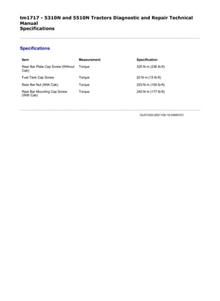
- 1. tm1717 - 5310N and 5510N Tractors Diagnostic and Repair Technical Manual Specifications Specifications Item Measurement Specification Rear Bar Plate Cap Screw (Without Cab) Torque 320 N·m (236 lb-ft) Fuel Tank Cap Screw Torque 20 N·m (15 lb-ft) Rear Bar Nut (With Cab) Torque 203 N·m (150 lb-ft) Rear Bar Mounting Cap Screw (With Cab) Torque 240 N·m (177 lb-ft) OUO1020,0001159-19-03MAY01 1/1 2020/1/5file:///C:/ProgramData/Service%20ADVISOR/Temp/tm1717_LVOUO1020988...
- 2. tm1717 - 5310N and 5510N Tractors Diagnostic and Repair Technical Manual Remove and Install Rear Bar-Without Cab Remove and Install Rear Bar-Without Cab 1. LV678-UN: Fuel Tank Drain Hose LEGEND: A - Drain Valve Disconnect battery, negative (–) cable first. 2. Remove fenders. (See Remove and Install Fenders in Section 80, Group 15.) 3. NOTE: Approximate capacity of fuel tank is 64 L (17.0 U.S. gal). Connect drain hose to drain valve (A) and drain fuel tank. 4. LV680-UN: PTO Lever Damper 1/4 2020/1/5file:///C:/ProgramData/Service%20ADVISOR/Temp/tm1717_LVOUO1032961...
- 3. LV681-UN: Wire Connectors LEGEND: A - PTO Lever Damper B - Fuel Hose C - Fuel Hose D - Wiring Connectors E - Clamps F - Wiring Lead G - Cap Screw Remove PTO lever damper (A) from rear bar. 5. Disconnect fuel hoses (B and C). Close all openings using caps or plugs. 6. Disconnect wires (D) from rear flood light. 7. Loosen four clamps (E). 8. Tag and disconnect wiring leads (F) from fuel level sender. 9. Remove three cap screws (G). 10. Remove fuel tank from rear bar. 2/4 2020/1/5file:///C:/ProgramData/Service%20ADVISOR/Temp/tm1717_LVOUO1032961...
- 4. 11. LV682-UN: Rear Bar LEGEND: A - Rear Bar B - Cap Screw (4 used) C - Plate Attach a suitable lifting device to rear bar (A). 12. Remove four cap screws (B) and plate (C). 13. Repeat procedure for opposite side. Remove rear bar. 14. NOTE: Remove rear flood light if rear bar replacement is necessary. Inspect all parts for damage. Replace as necessary. 15. Install rear bar (A). 16. Install plate (C) and cap screws (B). Tighten cap screws to specification. 17. Item Measurement Specification Rear Bar Plate Cap Screw (Without Cab) Torque 320 N·m (236 lb-ft) 3/4 2020/1/5file:///C:/ProgramData/Service%20ADVISOR/Temp/tm1717_LVOUO1032961...
- 5. LV680-UN: PTO Lever Damper LV681-UN: Wire Connectors LEGEND: A - PTO Lever Damper B - Fuel Hose C - Fuel Hose D - Wiring Connectors E - Clamps F - Wiring Lead G - Cap Screw Install fuel tank and cap screws (G). Tighten cap screws to specification. 18. Connect wiring leads (F). 19. Connect wires (D) to rear flood light. 20. Connect fuel hoses (B and C). 21. Tighten clamps (E) and install damper (A). 22. Install fenders. 23. Fill fuel tank with proper grade of fuel. (See Diesel Fuel Specifications in Section 10, Group 20.) 24. Connect battery, negative (–) last. Item Measurement Specification Fuel Tank Cap Screw Torque 20 N·m (15 lb-ft) AG,OUO1032,3421-19-21JUN00 4/4 2020/1/5file:///C:/ProgramData/Service%20ADVISOR/Temp/tm1717_LVOUO1032961...
- 6. tm1717 - 5310N and 5510N Tractors Diagnostic and Repair Technical Manual Remove and Install Rear Bar-With Cab Remove and Install Rear Bar-With Cab 1. NOTE: Removal of cab floor plates is not necessary. LV680-UN: Damper LEGEND: A - Damper Remove cab. (See Remove Cab and Floor Plates in Group 20.) 2. Remove fenders. (See Remove and Install Fenders in Section 80, Group 15.) 3. Remove fuel tank. (See Remove, Inspect, and Install Fuel Tank-Tractors With Cab in Section 30, Group 05.) 4. NOTE: Seat and SCV cover removed for illustration purposes only. Remove PTO lever damper (A) from rear bar. 1/3 2020/1/5file:///C:/ProgramData/Service%20ADVISOR/Temp/tm1717_LVOUO1032961...
- 7. 5. LV1806-UN: Rear Bar LEGEND: A - Cap Screw (2 used) B - Nut C - Flat Washer D - Rubber Washer Attach a suitable lifting device to rear bar. 6. Remove two cap screws (A). 7. Remove nut (B), flat washer (C), and rubber washer (D). 8. Repeat procedure for opposite side. Remove rear bar. 9. Inspect all parts for damage. Replace as necessary. 10. Install rear bar. 11. Install rubber washer (D), flat washer (C), and nut (B) on both sides of tractor. Tighten nuts (B) to specification. 12. Install cap screws (A) on both sides of rear bar. Tighten to specification. Item Measurement Specification Rear Bar Nut (With Cab) Torque 203 N·m (150 lb-ft) Item Measurement Specification Rear Bar Mounting Cap Screw (With Cab) Torque 240 N·m (177 lb-ft) 2/3 2020/1/5file:///C:/ProgramData/Service%20ADVISOR/Temp/tm1717_LVOUO1032961...
- 8. 13. LV680-UN: Damper LEGEND: A - Damper Install fuel tank. (See Remove, Inspect, and Install Fuel Tank-Tractors With Cab in Section 30, Group 05.) 14. Install cab. (See Install Cab and Floor Plates in Group 20.) 15. Install damper (A). 16. Install fenders. (See Remove and Install Fenders in Section 80, Group 15.) AG,OUO1032,3422-19-21JUN00 3/3 2020/1/5file:///C:/ProgramData/Service%20ADVISOR/Temp/tm1717_LVOUO1032961...
- 9. tm1717 - 5310N and 5510N Tractors Diagnostic and Repair Technical Manual Specifications Specifications Item Measurement Specification Cab Floor Plate Cap Screw Torque 240 N·m (177 lb-ft) Transmission Cover Cap Screw Torque 28 N·m (21 lb-ft) Cab Mounting Bolt Torque 203 N·m (150 lb-ft) Cab-to-Rear Bar Cap Screw Torque 225 N·m (166 lb-ft) Lower Window Mounting Nut Torque 1.5 N·m (13.3 lb-in.) Rear Side Window Screw and Lock Nut Torque 1.5 N·m (13.3 lb-in.) Windshield Nut Torque 1.5 N·m (13.3 lb-in.) Cab Door Hinge Cap Screws Torque 10 N·m (89 lb-in.) OUO1087,0000BC0-19-09MAY01 1/1 2020/1/5file:///C:/ProgramData/Service%20ADVISOR/Temp/tm1717_TXOUO1087989...
- 10. tm1717 - 5310N and 5510N Tractors Diagnostic and Repair Technical Manual Other Material Other Material Number Name Use R36757 (U.S.) John Deere Filter Element Cleaner Used to clean cab fresh air filter. OUO1087,0000BC3-19-09MAY01 1/1 2020/1/5file:///C:/ProgramData/Service%20ADVISOR/Temp/tm1717_TXOUO1087989...
- 11. tm1717 - 5310N and 5510N Tractors Diagnostic and Repair Technical Manual Essential Tools Essential Tools NOTE: Order tools according to information given in the U.S. SERVICEGARD™ Catalog or from the European Microfiche Tool Catalog (MTC). Cab Lifting Bar.......JDG1580 To remove and install cab. SERVICEGARD is a trademark of Deere & Company OUO1079,00004FC-19-13MAY03 1/1 2020/1/5file:///C:/ProgramData/Service%20ADVISOR/Temp/tm1717_LVOUO1079102...
- 12. tm1717 - 5310N and 5510N Tractors Diagnostic and Repair Technical Manual Remove Cab and Floor Plates Remove Cab and Floor Plates 1. LV1880-UN: Crop Guard LEGEND: A - Cap Screws B - Left Crop Guard Recover/recycle air conditioning refrigerant. (See Recover/Recycle Air Conditioning Refrigerant in Group 25.) 2. Drain engine coolant from radiator. 3. Disconnect battery, negative (–) cable first. 4. Remove cap screws (A) and left crop guard (B). 5. NOTE: Close all opening using caps and plugs. 1/10 2020/1/5file:///C:/ProgramData/Service%20ADVISOR/Temp/tm1717_LVOUO1023108...
- 13. LV1655-UN: Heater Hoses LV2521-UN: Wiring Connector LV2293-UN: Fuse Link Junction Block Post LEGEND: 2/10 2020/1/5file:///C:/ProgramData/Service%20ADVISOR/Temp/tm1717_LVOUO1023108...
- 14. A - Inlet Heater Hose B - Return Heater Hose C - Wiring Connector D - Fuse Link Junction Block Post Disconnect heater hoses (A and B) at left front cab post. Tag hoses for identification during installation. Cap or plug hoses and tubes. 6. Disconnect wiring connectors (C). 7. Disconnect red wire lead from right post (D) of fusible link junction block, located on the right side of engine. 8. Cut all tie straps as necessary and route red wire lead from fuse link junction block away from engine. 9. LV2522-UN: Right Crop Guard 3/10 2020/1/5file:///C:/ProgramData/Service%20ADVISOR/Temp/tm1717_LVOUO1023108...
- 15. Thank you very much for your reading. Please Click Here. Then Get COMPLETE MANUAL. NO WAITING NOTE: If there is no response to click on the link above, please download the PDF document first and then click on it.
- 16. LV2523-UN: A/C Tubes LEGEND: A - Cap Screw and Nut B - Cap Screw (3 used) C - Right Crop Guard D - Air Conditioning Tubes E - Wire Harness Connector Remove cap screw and nut (A) on bottom of crop guard. 10. Remove three cap screws (B) and right crop guard (C). 11. Disconnect air conditioning tubes (D) from right front cab post. Close tube openings using caps and plugs to prevent contamination. 12. Disconnect wire harness connector (E). 13. Remove left and right cab floor mats to access cab mounting hardware. 4/10 2020/1/5file:///C:/ProgramData/Service%20ADVISOR/Temp/tm1717_LVOUO1023108...
- 17. 14. LV1658-UN: Cab Mounting Hardware LV1659-UN: Cab Mounting Hardware LEGEND: 5/10 2020/1/5file:///C:/ProgramData/Service%20ADVISOR/Temp/tm1717_LVOUO1023108...
- 18. A - Rubber Grommet and Bolt B - Ground Cable C - Rubber Grommet and Bolt Remove left cab mounting nut, flat washer, rubber grommet, and bolt (A). 15. Disconnect ground cable (B). 16. Remove right cab mounting nut, flat washer, rubber grommet, and bolt (C). 17. LV1660-UN: Support Bar LEGEND: A - Bolt (2 used) Remove windshield washer tank and rear cab upholstery liner behind cab seat. 18. Remove two bolts (A) from rear cab support bar. 19. LV7943-UN: Cab Lifting Tool-Eyebolt-to-Cab Installation 6/10 2020/1/5file:///C:/ProgramData/Service%20ADVISOR/Temp/tm1717_LVOUO1023108...