
Recommended
Recommended
More Related Content
Similar to Caterpillar Cat 973 TRACK LOADER (Prefix 91L) Service Repair Manual (91L00001 and up).pdf
Similar to Caterpillar Cat 973 TRACK LOADER (Prefix 91L) Service Repair Manual (91L00001 and up).pdf (13)
More from fjkskkedmm4r
More from fjkskkedmm4r (20)
Recently uploaded
Recently uploaded (20)
Caterpillar Cat 973 TRACK LOADER (Prefix 91L) Service Repair Manual (91L00001 and up).pdf
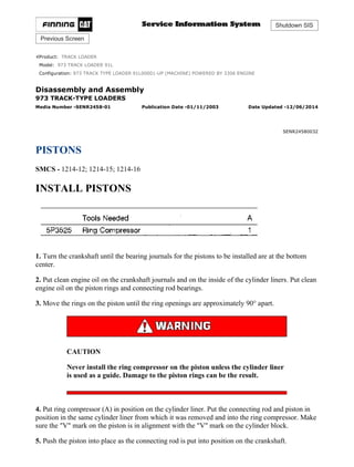
- 1. Shutdown SIS Previous Screen Product: TRACK LOADER Model: 973 TRACK LOADER 91L Configuration: 973 TRACK TYPE LOADER 91L00001-UP (MACHINE) POWERED BY 3306 ENGINE Disassembly and Assembly 973 TRACK-TYPE LOADERS Media Number -SENR2458-01 Publication Date -01/11/2003 Date Updated -12/06/2014 SENR24580032 PISTONS SMCS - 1214-12; 1214-15; 1214-16 INSTALL PISTONS 1. Turn the crankshaft until the bearing journals for the pistons to be installed are at the bottom center. 2. Put clean engine oil on the crankshaft journals and on the inside of the cylinder liners. Put clean engine oil on the piston rings and connecting rod bearings. 3. Move the rings on the piston until the ring openings are approximately 90° apart. CAUTION Never install the ring compressor on the piston unless the cylinder liner is used as a guide. Damage to the piston rings can be the result. 4. Put ring compressor (A) in position on the cylinder liner. Put the connecting rod and piston in position in the same cylinder liner from which it was removed and into the ring compressor. Make sure the "V" mark on the piston is in alignment with the "V" mark on the cylinder block. 5. Push the piston into place as the connecting rod is put into position on the crankshaft. 1/5 973 TRACK TYPE LOADER 91L00001-UP (MACHINE) POWERED BY 3306 EN... 2021/11/14 https://127.0.0.1/sisweb/sisweb/techdoc/techdoc_print_page.jsp?returnurl=/sis...
- 2. 6. Put clean engine oil on bearings, bolt threads and surfaces of the nuts that make contact with the connecting rod caps. Put caps (1) in position on the connecting rods and install the nuts. Tighten the nuts to a torque of 40 ± 4 N·m (30 ± 3 lb ft). Put a mark on each nut and the end of each bolt. Tighten the nuts 90° more. CAUTION When connecting rod caps are installed, make sure the number on the side of the cap is next to and respective with the number on the side of the connecting rod. 7. Follow the same above procedure for installation of the remainder of the pistons. End By: a) install oil pan b) install cylinder head TYPICAL EXAMPLE 2/5 973 TRACK TYPE LOADER 91L00001-UP (MACHINE) POWERED BY 3306 EN... 2021/11/14 https://127.0.0.1/sisweb/sisweb/techdoc/techdoc_print_page.jsp?returnurl=/sis...
- 3. DISASSEMBLE PISTONS Start By: a) remove pistons 1. Remove the rings from the piston with tool (A). 2. Remove the bearings from the connecting rod and connecting rod cap. 3. Remove retaining rings (3), pin (1) and connecting rod (2) from the piston. 4. See USE OF PISTON BEARING REMOVAL AND INSTALLATION TOOLS, SPECIAL INSTRUCTIONS, Form No. SMHS7295-02 for more information of removal and installation of piston pin bearings. 5. Heat the connecting rod to a temperature of 176 to 260°C (350 to 500°F). Put 6V3029 Spacer (11) in the base plate. Put the connecting rod on the base plate of tooling (B). 6. Put the connecting rod piston pin bearing end in the center of the port assembly of tooling (B). Install pin (6) in the center of the bore for the connecting rod bearings. 3/5 973 TRACK TYPE LOADER 91L00001-UP (MACHINE) POWERED BY 3306 EN... 2021/11/14 https://127.0.0.1/sisweb/sisweb/techdoc/techdoc_print_page.jsp?returnurl=/sis...
- 4. 7. Install 6V2049 Adapter (9). Put the hole in the adapter in alignment with the holes in the base plate of tooling (B). 8. Install clamp bar (10) and clamp pin (7). 9. Install new piston pin bearing (5) on adapter (9). NOTE: The old bearing is pushed out by tooling (B) as the new bearing is installed. 10. Put 5P8645 Adapter (8) in position as shown with the taper side down. The piston pin bearing joint must be in alignment with the hole in the adapter (9) and the base plate of tooling (B). 11. Put pusher (4) on adapter (8). 12. Use tooling (B) to push the new piston pin bearing into the connecting rod until adapter (8) of tooling (B) makes full contact with the connecting rod surface. 13. Remove the connecting rod and the old piston bearing from tooling (B). 14. Check the piston pin bearing bore diameter after the bearing is installed. The correct dimension is 43.210 ± 0.008 mm (1.7012 ± .0003 in). ASSEMBLE PISTONS 4/5 973 TRACK TYPE LOADER 91L00001-UP (MACHINE) POWERED BY 3306 EN... 2021/11/14 https://127.0.0.1/sisweb/sisweb/techdoc/techdoc_print_page.jsp?returnurl=/sis...
- 5. 1. Install the connecting rod (4) in the piston with the bearing tab groove (slot) (1) on the same side as the cutout (depression) (3) on the head of the piston. 2. Install piston pin (2) and retaining rings (5) in piston. 3. When old pistons are to be used, clean the piston grooves with an acceptable piston groove cleaning tool. 4. Install the spring for the oil ring. Install the oil ring with tool (A). The gap in the ring must be approximately 180° from the oil ring spring connections. 5. The two compression rings have marks "UP-1" and "UP-2." The rings must be installed with these marks toward the top of the piston with "UP-1" as the top ring. After installation of all three piston rings, put piston rings in position so gaps in rings are 120° apart. NOTE: Compression rings that do not have identification can be installed either way. 6. To check the clearance between the piston ring grooves and rings, see Specifications. 7. See SPECIFICATIONS to check the clearance between the ends of the piston rings (end gap). End By: a) install pistons Copyright 1993 - 2021 Caterpillar Inc. All Rights Reserved. Private Network For SIS Licensees. Sun Nov 14 14:13:16 UTC+0800 2021 5/5 973 TRACK TYPE LOADER 91L00001-UP (MACHINE) POWERED BY 3306 EN... 2021/11/14 https://127.0.0.1/sisweb/sisweb/techdoc/techdoc_print_page.jsp?returnurl=/sis...
- 6. Shutdown SIS Previous Screen Product: TRACK LOADER Model: 973 TRACK LOADER 91L Configuration: 973 TRACK TYPE LOADER 91L00001-UP (MACHINE) POWERED BY 3306 ENGINE Disassembly and Assembly 973 TRACK-TYPE LOADERS Media Number -SENR2458-01 Publication Date -01/11/2003 Date Updated -12/06/2014 SENR24580033 CYLINDER LINERS SMCS - 1216-11; 1216-12 REMOVE CYLINDER LINERS Start By: a) remove pistons 1. Remove the coolant from the cylinder block. 2. Put covers on journals of crankshaft for protection from dirt or water. 3. Remove cylinder liners (1) with tooling (A). 1/4 973 TRACK TYPE LOADER 91L00001-UP (MACHINE) POWERED BY 3306 EN... 2021/11/14 https://127.0.0.1/sisweb/sisweb/techdoc/techdoc_print_page.jsp?returnurl=/sis...
- 7. INSTALL CYLINDER LINERS 1. Clean the cylinder liners (3) and the liner bores in the cylinder block. 2. Install the cylinder liners in the block without the O-ring seals or filler bands. 3. Check the cylinder liner projection as follows: a) Install the S1589 Bolts (2) and 1S379 Washers of tooling (B) on the cylinder block next to each liner. Tighten the bolts evenly, in four steps: 14 N·m (10 lb ft), 35 N·m (25 lb ft), 70 N·m (50 lb ft), and 95 N·m (70 lb ft). b) Put adapter plate on top of the liner and install the remainder of tooling (B). Tighten the 1D4595 Bolts (1) evenly in four steps: 7 N·m (5 lb ft), 20 N·m (15 lb ft), 35 N·m (25 lb ft), and 70 N·m (50 lb ft). 2/4 973 TRACK TYPE LOADER 91L00001-UP (MACHINE) POWERED BY 3306 EN... 2021/11/14 https://127.0.0.1/sisweb/sisweb/techdoc/techdoc_print_page.jsp?returnurl=/sis...
- 8. c) Check to be sure the distance from the bottom edge of the crossbar to the top of the cylinder block is the same on both sides of the liner. d) Check the cylinder liner projection with tool group (C) at four locations around the liner. e) Liner projection must be 0.033 to 0.175 mm (.0012 to .0069 in) (make the measurement to the top of the liner flange, not the inner ring). The maximum differential between high and low measurements made at four places around each liner is 0.05 mm (.002 in). The average projection of liners next to each other must not be more than 0.05 mm (.002 in). The maximum difference in the average projection of all cylinder liners under each cylinder head must not be more than 0.10 mm (.004 in). NOTE: If the liner is turned in the bore, it can make a difference in the liner projection. 4. If the liner projection is not 0.033 to 0.175 mm (.0012 to .0069 in), check the thickness of the following parts: spacer plate, spacer plate gasket and cylinder liner flange. The thickness of the spacer plate must be 9.970 ± 0.025 mm (.3925 ± .0010 in). The thickness of the spacer plate gasket must be 0.208 ± 0.025 mm (.0082 ± .0010 in). The thickness of the cylinder liner flange must be 10.282 ± 0.020 mm (.4048 ± .0008 in). NOTE: If the liner projection changes from point to point around the liner, turn the liner to a new position in the bore. If the liner projection is still not to specifications, move the liner to a different bore. 5. When the cylinder projection is correct, put a mark on the liner and block so the liner can be installed in the same position from which it was removed. NOTE: Cylinder liner projection can be adjusted by the removal of material from (machining) the contact face of the cylinder block with the use of the 8S3140 Cylinder Block Counterboring Tool Arrangement. Machine to a minimum depth of 0.76 mm (.030 in) and to a maximum depth of 1.14 mm (.045 in). The instructions for the use of the tool group are in Special Instruction, Form No. FM055228. Shims are available for the adjustment of the liner projection. See CYLINDER LINER PROJECTION in TESTING AND ADJUSTING for the shim thickness and part number. 3/4 973 TRACK TYPE LOADER 91L00001-UP (MACHINE) POWERED BY 3306 EN... 2021/11/14 https://127.0.0.1/sisweb/sisweb/techdoc/techdoc_print_page.jsp?returnurl=/sis...
- 9. 6. Remove tooling (B) and (C). Remove the liner. 7. Put liquid soap on bottom liner bore in block, on grooves in lower liner and on O-ring seals (4). Install O-ring seals on the liner. 8. Put filler band (5) in clean SAE 30 oil for a moment and install on the liner. Install cylinder liner immediately in the cylinder block (before expansion of filler band). 9. Make sure the mark on liner is in alignment with the mark on the block. Use tooling (A) to push the liner into position. 10. Do Steps 5 through 9 for the remainder of the cylinder liners. End By: a) install pistons Copyright 1993 - 2021 Caterpillar Inc. All Rights Reserved. Private Network For SIS Licensees. Sun Nov 14 14:14:12 UTC+0800 2021 4/4 973 TRACK TYPE LOADER 91L00001-UP (MACHINE) POWERED BY 3306 EN... 2021/11/14 https://127.0.0.1/sisweb/sisweb/techdoc/techdoc_print_page.jsp?returnurl=/sis...
- 10. Shutdown SIS Previous Screen Product: TRACK LOADER Model: 973 TRACK LOADER 91L Configuration: 973 TRACK TYPE LOADER 91L00001-UP (MACHINE) POWERED BY 3306 ENGINE Disassembly and Assembly 973 TRACK-TYPE LOADERS Media Number -SENR2458-01 Publication Date -01/11/2003 Date Updated -12/06/2014 SENR24580034 CONNECTING ROD BEARINGS SMCS - 1219-10 REMOVE AND INSTALL CONNECTING ROD BEARINGS Start By: a) remove oil pump b) remove oil pan plate 1. Turn the crankshaft until two pistons are at the bottom center. Remove connecting rod caps (1) from the two connecting rods. Remove the lower half of the rod bearing from the rod bearing cap. 2. Push the connecting rods away from the crankshaft. Remove the upper half of the rod bearing from the connecting rod. NOTE: Install the connecting rod bearings dry when the clearance checks are made. Put clean engine oil on the connecting rod bearings for final assembly. 3. Install the upper half of the rod bearing in the connecting rod. 4. Install the lower half of the rod bearing in the connecting rod cap. NOTE: Be sure the tabs in the back of the connecting rod bearings are in the tab grooves of the connecting rod and cap. 5. Use Plastigage (A) to check the connecting rod bearing clearance. 1/3 973 TRACK TYPE LOADER 91L00001-UP (MACHINE) POWERED BY 3306 EN... 2021/11/14 https://127.0.0.1/sisweb/sisweb/techdoc/techdoc_print_page.jsp?returnurl=/sis...
- 11. 6. Put Plastigage (A) on the connecting rod bearing. 7. Put clean engine oil on the threads of the rod bolts and seat surfaces of the nuts. CAUTION When connecting rod caps are installed, make sure the number on the side of the cap is next to and respective with the number on the side of the connecting rod. NOTE: Do not turn the crankshaft when Plastigage (A) is in position. CAUTION Do not use an impact wrench to tighten the nuts an additional 90°. 8. Install connecting rod cap (1). Install the nuts. Tighten the nuts to a torque of 40 ± 4 N·m (30 ± 3 lb ft). Put a mark on each nut and the end of each bolt. Tighten the nuts 90° more. Remove the connecting rod caps. Remove Plastigage (A) and measure the width of the Plastigage. The connecting rod clearance must be 0.076 to 0.168 mm (.0030 to .0066 in) for new bearings. The maximum clearance with used bearings is 0.25 mm (.010 in). 2/3 973 TRACK TYPE LOADER 91L00001-UP (MACHINE) POWERED BY 3306 EN... 2021/11/14 https://127.0.0.1/sisweb/sisweb/techdoc/techdoc_print_page.jsp?returnurl=/sis...
- 12. 9. Install the connecting rod caps and tighten the nuts as in Step 8. 10. Do Steps 1 through 9 for the remainder of the connecting rod bearings. End By: a) install oil pan plate b) install oil pump Copyright 1993 - 2021 Caterpillar Inc. All Rights Reserved. Private Network For SIS Licensees. Sun Nov 14 14:15:07 UTC+0800 2021 3/3 973 TRACK TYPE LOADER 91L00001-UP (MACHINE) POWERED BY 3306 EN... 2021/11/14 https://127.0.0.1/sisweb/sisweb/techdoc/techdoc_print_page.jsp?returnurl=/sis...
- 13. Shutdown SIS Previous Screen Product: TRACK LOADER Model: 973 TRACK LOADER 91L Configuration: 973 TRACK TYPE LOADER 91L00001-UP (MACHINE) POWERED BY 3306 ENGINE Disassembly and Assembly 973 TRACK-TYPE LOADERS Media Number -SENR2458-01 Publication Date -01/11/2003 Date Updated -12/06/2014 SENR24580035 CRANKSHAFT MAIN BEARINGS SMCS - 1219-10 REMOVE AND INSTALL CRANKSHAFT MAIN BEARINGS Start By: a) remove oil pump b) remove oil pan plate 1. Remove the No. 1, 3, 5 and 7 main bearing caps (1). Remove the crankshaft thrust bearing from the No. 7 main bearing. 2. Remove the lower half of the main bearing from the main bearing caps. CAUTION If the crankshaft is turned in the wrong direction, the tab on the bearing will be pushed between the crankshaft and bearing area in block which can cause damage to the block or crankshaft. 1/4 973 TRACK TYPE LOADER 91L00001-UP (MACHINE) POWERED BY 3306 EN... 2021/11/14 https://127.0.0.1/sisweb/sisweb/techdoc/techdoc_print_page.jsp?returnurl=/sis...
- 14. 3. Install tool (A) in oil hole in the crankshaft journal and remove the upper half of the main bearing as the crankshaft is turned and the main bearing is moved out of the cylinder block. NOTE: Install the main bearings dry when the clearance checks are made. Put clean engine oil on the main bearings for final assembly. CAUTION Make sure the upper and lower halves of the main bearings are installed so the bearing tabs fit into the notch in cylinder block and the main bearing caps. 4. Install new lower half of main bearings (2) in the main bearing caps. Use tool (A) and install the upper half of the main bearings in the cylinder block. 5. Put clean oil on the thrust bearing and install a new thrust bearing with the identification "BLOCK SIDE" toward the cylinder block and the tabs on the thrust bearings in the machined area in the cylinder block. NOTE: When the bearing clearance is checked and the engine is in a vertical position, such as in the vehicle, the crankshaft will have to be lifted up and held against the upper halves of the main bearings to get a correct measurement with the Plastigage. The Plastigage will not hold the weight of the crankshaft and give a correct indication. If the engine is in a horizontal position, it is not 2/4 973 TRACK TYPE LOADER 91L00001-UP (MACHINE) POWERED BY 3306 EN... 2021/11/14 https://127.0.0.1/sisweb/sisweb/techdoc/techdoc_print_page.jsp?returnurl=/sis...
- 15. necessary to hold the crankshaft up. Do not turn the crankshaft when the Plastigage is in position to check clearances. 6. Check the main bearing clearances with Plastigage (B) as follows: a. Put a piece of Plastigage (B) on the surface of the lower half of the main bearing. CAUTION Make sure the part number on the main bearing cap is toward the front of the engine and the number on the main bearing cap is the same as the number on the cylinder block on the left side of each main bearing cap. NOTE: Do not turn the crankshaft when Plastigage (B) is in position. b) Install main bearing caps (1) for No. 1, 3, 5 and 7 main bearings. Put clean engine oil on the bolt threads and the face of the washers and install the bolts. Tighten the bolts to a torque of 40 ± 4 N·m (30 ± 3 lb ft). CAUTION Do not use an impact wrench to tighten the bolts an additional 90° more. c) Put a mark on each bolt and main bearing cap, then tighten the bolts 90° more. d) Remove the main bearing caps for No. 1, 3, 5 and 7 main bearings. Remove Plastigage (B) and measure the width of the Plastigage. The main bearing clearance must be 0.076 to 0.165 mm (.0030 to .0065 in). Maximum permissible clearance with used bearings is 0.25 mm (.010 in). 7. Install main bearing caps (1) and tighten the bolts as in Step 6b and 6c. 8. Remove No. 2, 4 and 6 main bearing caps. Do Steps 2, 3, 4, 6 and 7 for the No. 2, 4 and 6 main bearings. 9. Check the crankshaft end play with tooling (C). The end play is controlled by the thrust bearings on the No. 7 main bearing. End play with new bearings is 0.064 to 0.386 mm (.0025 to .0145 in). The maximum permissible end play with used bearings is 0.64 mm (.025 in). End By: a) install oil pan plate 3/4 973 TRACK TYPE LOADER 91L00001-UP (MACHINE) POWERED BY 3306 EN... 2021/11/14 https://127.0.0.1/sisweb/sisweb/techdoc/techdoc_print_page.jsp?returnurl=/sis...
- 16. b) install oil pump TYPICAL EXAMPLE Copyright 1993 - 2021 Caterpillar Inc. All Rights Reserved. Private Network For SIS Licensees. Sun Nov 14 14:16:03 UTC+0800 2021 4/4 973 TRACK TYPE LOADER 91L00001-UP (MACHINE) POWERED BY 3306 EN... 2021/11/14 https://127.0.0.1/sisweb/sisweb/techdoc/techdoc_print_page.jsp?returnurl=/sis...
- 17. Shutdown SIS Previous Screen Product: TRACK LOADER Model: 973 TRACK LOADER 91L Configuration: 973 TRACK TYPE LOADER 91L00001-UP (MACHINE) POWERED BY 3306 ENGINE Disassembly and Assembly 973 TRACK-TYPE LOADERS Media Number -SENR2458-01 Publication Date -01/11/2003 Date Updated -12/06/2014 SENR24580036 VIBRATION DAMPER AND PULLEY SMCS - 1153-11; 1153-12; 1205-11; 1205-12 REMOVE VIBRATION DAMPER AND PULLEY Start By: a) remove radiator and guard 1. Fasten a strap and hoist to fan (1) and remove the fan from the fan drive. The weight is approximately 39 kg (85 lb). 2. Remove bolts (3), the ring and damper assembly (4) from the pulley. 3. Remove V-belts (2). 4. Use two 1/2" -13 NC bolts 1 3/4 inches long to fasten bar (5) to the pulley so it can not turn while bolt (6) is loosened. Bar (5) is 9.5 mm x 19.0 mm x 762 mm (.375 inches x .75 inches x .30 1/6 973 TRACK TYPE LOADER 91L00001-UP (MACHINE) POWERED BY 3306 EN... 2021/11/14 https://127.0.0.1/sisweb/sisweb/techdoc/techdoc_print_page.jsp?returnurl=/sis...
- 18. inches). Remove bolt (6) and the washer from the crankshaft. Install a 3.2 mm (.125 in) thick spacer on bolt (6) and install bolt (6) back in the crankshaft. The spacer will give clearance between the washer and bolt (6) on the pulley. NOTE: With the use of the spacer, the force during the removal of the pulley will be on the end of the crankshaft rather than on the bolt threads. CAUTION If the spacer is not used the bolt threads can be damaged. 5. Install tooling (A) and loosen the pulley from the crankshaft. 6. Remove tooling (A). Remove the bolt, washer, spacer and pulley from the crankshaft. 2/6 973 TRACK TYPE LOADER 91L00001-UP (MACHINE) POWERED BY 3306 EN... 2021/11/14 https://127.0.0.1/sisweb/sisweb/techdoc/techdoc_print_page.jsp?returnurl=/sis...
- 19. INSTALL VIBRATION DAMPER AND PULLEY 1. Put pulley (1) in position on the crankshaft. Install washer (2) on bolt (3) so the maximum flat area of the washer will be next to the pulley. Install bolt (3) in the crankshaft. 2. Use two 1/2" -13 NC bolts 1 3/4 in. long to fasten bar (4) to the pulley so it can not turn while the bolt is tightened. Bar (4) is 9.5 mm x 19.0 mm x 762 mm (.375 in. x .75 in. x 30 in.). 3. Tighten bolt (3) to a torque of 312 ± 27 N·m (231 ± 20 lb ft). Hit the bolt with a hammer. Tighten the bolt again to a torque of 312 ± 27 N·m (231 ± 20 lb ft). 4. Install the V-belts and adjust them to the correct tension. See FAN BELTS INSTALLATION for the correct tension. 5. Put vibration damper (5) and ring (6) in position on the pulley and install the bolts that hold them in place. Tighten the bolts to a torque of 135 ± 15 N·m (100 ± 11 lb ft). 6. Fasten a strap and hoist to fan (7) and install the fan on the fan drive. Weight of the fan is approximately 39 kg (85 lb). 3/6 973 TRACK TYPE LOADER 91L00001-UP (MACHINE) POWERED BY 3306 EN... 2021/11/14 https://127.0.0.1/sisweb/sisweb/techdoc/techdoc_print_page.jsp?returnurl=/sis...
- 20. REMOVE ENGINE FRONT SUPPORT Start By: a) remove vibration damper and pulley 1. Remove the two guards below the track motors and transmission. The weight of each guard is approximately 63 kg (140 lb). 2. Remove radiator elbow (1). 3. Install a floor jack under support (2). Remove the bolts that hold the support in place and remove the support. The weight is approximately 27 kg (60 lb). 4. Loosen bolts (3) in the transmission mounts on both sides of the machine. 5. Remove bolts (4) and the lower rubber mounts and sleeves. 6. Fasten a hoist to the front of the engine and lift the front of the engine just enough to remove the top halves of the rubber mounts between the engine front support and the frame. Install blocks (5) under the flywheel housing to hold the weight of the engine. Lower the engine on to blocks (5) and remove the hoist. 7. Remove the bolts that hold engine front support (6) to the timing gear cover and remove the engine front support. INSTALL ENGINE FRONT SUPPORT 1. Put engine front support (1) in position on the timing gear cover and install the bolts that hold it in place. Tighten the bolts to a torque of 135 ± 15 N·m (100 ± 11 lb ft). 2. Fasten a hoist to the front of the engine and lift the front of the engine just enough to remove the blocks from under the flywheel housing. Install the top rubber mounts (2) between the engine front support and frame. Lower the front of the engine on to the rubber mounts. Put the bottom rubber mounts (3) and sleeves (4) in position below the plate on the frame as shown. 4/6 973 TRACK TYPE LOADER 91L00001-UP (MACHINE) POWERED BY 3306 EN... 2021/11/14 https://127.0.0.1/sisweb/sisweb/techdoc/techdoc_print_page.jsp?returnurl=/sis...
- 21. 3. Install bolts (5), washers and nuts in the engine front support. Tighten bolts (5) to a torque of 570 ± 80 N·m (420 ± 60 lb ft). 4. Tighten bolts (6) in the transmission mounts to a torque of 475 ± 50 N·m (350 ± 37 lb ft). 5. Use a floor jack to put support (7) for the track motor guards in position under the machine and install the bolts that hold the support in place. 6. Install radiator elbow (8) as shown. 7. Install the guard below the track motors and transmission. The weight of each guard is approximately 63 kg (140 lb). 5/6 973 TRACK TYPE LOADER 91L00001-UP (MACHINE) POWERED BY 3306 EN... 2021/11/14 https://127.0.0.1/sisweb/sisweb/techdoc/techdoc_print_page.jsp?returnurl=/sis...
- 22. Copyright 1993 - 2021 Caterpillar Inc. All Rights Reserved. Private Network For SIS Licensees. Sun Nov 14 14:16:59 UTC+0800 2021 6/6 973 TRACK TYPE LOADER 91L00001-UP (MACHINE) POWERED BY 3306 EN... 2021/11/14 https://127.0.0.1/sisweb/sisweb/techdoc/techdoc_print_page.jsp?returnurl=/sis...
- 23. Shutdown SIS Previous Screen Product: TRACK LOADER Model: 973 TRACK LOADER 91L Configuration: 973 TRACK TYPE LOADER 91L00001-UP (MACHINE) POWERED BY 3306 ENGINE Disassembly and Assembly 973 TRACK-TYPE LOADERS Media Number -SENR2458-01 Publication Date -01/11/2003 Date Updated -12/06/2014 SENR24580037 CRANKSHAFT FRONT SEAL AND WEAR SLEEVE SMCS - 1160-11; 1160-12 REMOVE CRANKSHAFT FRONT SEAL AND WEAR SLEEVE Start By: a) remove crankshaft pulley NOTE: When a replacement of the front seal is made, a new wear sleeve must be installed also. 1. Use tooling (A) to remove the crankshaft front seal. 2. Install tool (C) in the seal bore. CAUTION Do not use the sharp edge of distorter (B) against ring (C) because distorter (13) will be damaged. 1/3 973 TRACK TYPE LOADER 91L00001-UP (MACHINE) POWERED BY 3306 EN... 2021/11/14 https://127.0.0.1/sisweb/sisweb/techdoc/techdoc_print_page.jsp?returnurl=/sis...
- 24. 3. Install tool (B) between tool (C) and the wear sleeve with the sharp edge against the wear sleeve. Turn tool (B) until the sharp edge of the tool makes a notch (crease) across the wear sleeve. Do this in two or more places until the wear sleeve is loose. 4. Remove tool (C) and the wear sleeve by hand. INSTALL CRANKSHAFT FRONT SEAL AND WEAR SLEEVE 1. Install the crankshaft front seal and wear sleeve with tooling (A) as follows: a) Put clean engine oil on the seal lip of seal (1) and on the outside diameter of wear sleeve (2). Install seal (1) on wear sleeve (2) as shown in Figure 1. b) Use 6V1541 Quick Cure Primer to clean the outside diameter of crankshaft (3) and the inside diameter of wear sleeve (2). c) Put 9S3265 Retaining Compound on the outside diameter of crankshaft (3) and inside diameter of wear sleeve (2). NOTE: Make sure the lip of the seal is toward the inside of the engine and the outside diameter bevel of the wear sleeve is toward the outside of the engine. d) Put wear sleeve (2) with seal (1) on the front of the crankshaft as shown in Figure 2. Install tooling (A). Tighten the bolt in tooling (A) until the inside surface of tooling (A) makes contact with the end of the crankshaft. End By: a) install crankshaft pulley 2/3 973 TRACK TYPE LOADER 91L00001-UP (MACHINE) POWERED BY 3306 EN... 2021/11/14 https://127.0.0.1/sisweb/sisweb/techdoc/techdoc_print_page.jsp?returnurl=/sis...
- 25. Copyright 1993 - 2021 Caterpillar Inc. All Rights Reserved. Private Network For SIS Licensees. Sun Nov 14 14:17:55 UTC+0800 2021 3/3 973 TRACK TYPE LOADER 91L00001-UP (MACHINE) POWERED BY 3306 EN... 2021/11/14 https://127.0.0.1/sisweb/sisweb/techdoc/techdoc_print_page.jsp?returnurl=/sis...
- 26. Shutdown SIS Previous Screen Product: TRACK LOADER Model: 973 TRACK LOADER 91L Configuration: 973 TRACK TYPE LOADER 91L00001-UP (MACHINE) POWERED BY 3306 ENGINE Disassembly and Assembly 973 TRACK-TYPE LOADERS Media Number -SENR2458-01 Publication Date -01/11/2003 Date Updated -12/06/2014 SENR24580038 TIMING GEAR COVER SMCS - 1166-11; 1166-12 REMOVE TIMING GEAR COVER Start By: a) remove engine front support b) remove fan drive c) remove water pump d) remove alternator* e) remove air conditioner compressor* *See VEHICLE SYSTEMS section. 1. Remove the brackets for the alternator and air conditioner compressor from the timing gear cover. 2. Loosen the bolts that hold the oil pan and plate to the cylinder block and install spacers (3) as shown. CAUTION Use care when the trunnion is removed and install to prevent damage to the crankshaft front seal. 1/4 973 TRACK TYPE LOADER 91L00001-UP (MACHINE) POWERED BY 3306 EN... 2021/11/14 https://127.0.0.1/sisweb/sisweb/techdoc/techdoc_print_page.jsp?returnurl=/sis...
- 27. Please write to us. Our email: aservicemanualpdf@yahoo.com Please go to the homepage to get the full manual, or other brand PDF manuals. Home Site: aservicemanualpdf.com
- 28. Thank you very much for your reading. Please Click Here. Then Get COMPLETE MANUAL. NO WAITING NOTE: If there is no response to click on the link above, please download the PDF document first and then click on it. GET MORE OTHER MANUALS https://www.aservicemanualpdf.com/ GET MORE OTHER MANUALS https://www.aservicemanualpdf.com/
- 29. 3. Remove bolts (1) that hold trunnion (2) to the timing gear cover. Remove the trunnion. 4. Remove cover (4) from the back of the timing gear plate. 5. Remove the bolts that hold timing gear cover (5) in place. Make a note of the location of the different length bolts. Carefully loosen the cover from the dowels and remove the cover. The weight of the timing gear cover is approximately 21 kg (46 lb). 6. Clean the old gasket from the contact surfaces of the timing gear cover and timing gear plate. INSTALL TIMING GEAR COVER 1. Install a new gasket on the timing gear plate. Cut the gasket even with the bottom face of the cylinder block. Put 5H2471 Gasket Cement on the bottom of the gasket where the gasket makes contact with the gasket for the oil pan plate. 2/4 973 TRACK TYPE LOADER 91L00001-UP (MACHINE) POWERED BY 3306 EN... 2021/11/14 https://127.0.0.1/sisweb/sisweb/techdoc/techdoc_print_page.jsp?returnurl=/sis...
- 30. 2. Put the timing gear cover in position on the timing gear plate and install the bolts in their original locations to hold the cover in place. Make sure the bolts in locations (1) and (2) are tightened to a torque of 23 ± 4 N·m (17 ± 3 lb ft). 3. Be sure the O-ring seal is in position on trunnion (3). Put trunnion (3) in position on the timing gear cover and install the bolts that hold it in place. Tighten the bolts to a torque of 135 ± 15 N·m (100 ± 11 lb ft). 4. Install the gasket and cover (4) on the back of the timing gear plate. 5. Remove the spacers between the oil pan plate and cylinder block. Install the bolts in the front of the oil pan and tighten all the bolts that hold the oil pan and plate in place. 6. Install the brackets for the alternator and air conditioner compressor on the timing gear cover. End By: a) install air conditioner compressor* b) install alternator* c) install water pump d) install fan drive e) install engine front support *See VEHICLE SYSTEMS section. 3/4 973 TRACK TYPE LOADER 91L00001-UP (MACHINE) POWERED BY 3306 EN... 2021/11/14 https://127.0.0.1/sisweb/sisweb/techdoc/techdoc_print_page.jsp?returnurl=/sis...
- 31. Copyright 1993 - 2021 Caterpillar Inc. All Rights Reserved. Private Network For SIS Licensees. Sun Nov 14 14:18:50 UTC+0800 2021 4/4 973 TRACK TYPE LOADER 91L00001-UP (MACHINE) POWERED BY 3306 EN... 2021/11/14 https://127.0.0.1/sisweb/sisweb/techdoc/techdoc_print_page.jsp?returnurl=/sis...