
Recommended
Recommended
More Related Content
Similar to Caterpillar Cat 973 TRACK LOADER (Prefix 66G) Service Repair Manual (66G00001 and up).pdf
Similar to Caterpillar Cat 973 TRACK LOADER (Prefix 66G) Service Repair Manual (66G00001 and up).pdf (20)
More from fjkskkedmm4r
More from fjkskkedmm4r (20)
Recently uploaded
Recently uploaded (20)
Caterpillar Cat 973 TRACK LOADER (Prefix 66G) Service Repair Manual (66G00001 and up).pdf
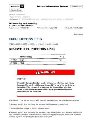
- 1. Shutdown SIS Previous Screen Product: TRACK LOADER Model: 973 TRACK LOADER 66G Configuration: 973 TRACK LOADER / HIGH DRIVE / 66G00001-UP (MACHINE) POWERED BY 3306 ENGINE Disassembly and Assembly 973 TRACK-TYPE LOADERS Media Number -SENR2458-01 Publication Date -01/11/2003 Date Updated -12/06/2014 SENR24580019 FUEL INJECTION LINES SMCS - 1252-11; 1252-12; 1256-11; 1256-12; 1256-15; 1256-16 REMOVE FUEL INJECTION LINES CAUTION Do not let the tops of the fuel nozzles (2) turn when fuel line nuts (1) are loosened. The nozzles will become damaged if the top of the nozzle turns in the body. The engine will be damaged if a damaged fuel injection nozzle is used because the shape of fuel (spray pattern) coming out of the nozzles will not be correct. 1. Hold tops (2) on the fuel nozzles with a wrench and loosen fuel line nuts (1) on the nozzles. 2. Remove bolt (3) from the clamp that holds the fuel lines to the cylinder head. 3. Loosen fuel line nuts (4) at the fuel injection pump. 4. Remove bolt (5) from the clamp that holds fuel lines (6) to cylinder head. Remove fuel lines (6) as a set and the other four fuel lines as a set. Install tooling (A) and (B) on the nozzles, fuel lines and fuel injection pump to keep dirt out of the fuel system. 1/9 973 TRACK LOADER / HIGH DRIVE / 66G00001-UP (MACHINE) POWERED B... 2021/12/1 https://127.0.0.1/sisweb/sisweb/techdoc/techdoc_print_page.jsp?returnurl=/sis...
- 2. INSTALL FUEL INJECTION LINES 1. Remove tooling (A) and (B) from the fuel injection pump, lines and nozzles. 2. Install fuel lines (2) as a set and the other four fuel lines as a set. Start the fuel line nuts on the nozzles and fuel injection pump. Install bolts (1) that hold the fuel lines to the cylinder head. 3. Use a wrench to hold the top of the nozzles. Use tool (C) and a torque wrench to tighten fuel line nuts (3) to a torque of 40 ± 7 N·m (30 ± 5 lb ft). The fuel lines must not make contact with other fuel lines or engine components except at fittings and clamps. NOTE: When a crowfoot wrench is used with a torque wrench, a correction is necessary for the dial reading. To find the amount of correction necessary use the Caterpillar Torque Computer, Form No. GEG02229 which is also Snap-On Form No. SS306B. End By: a) prime the fuel system* *See PRIMING FUEL SYSTEM in the MAINTENANCE GUIDE. 2/9 973 TRACK LOADER / HIGH DRIVE / 66G00001-UP (MACHINE) POWERED B... 2021/12/1 https://127.0.0.1/sisweb/sisweb/techdoc/techdoc_print_page.jsp?returnurl=/sis...
- 3. REMOVE FUEL TRANSFER PUMP 1. Remove fuel lines (1) and (2) from the fuel pump. 2. Remove bolts (3) and (5) and transfer pump (4). INSTALL FUEL TRANSFER PUMP 1. Make sure O-ring seal (2) is in position on the transfer pump. 2. Put transfer pump (1) in position and install the bolts and clip. 3. Install fuel lines (3) and (4). 3/9 973 TRACK LOADER / HIGH DRIVE / 66G00001-UP (MACHINE) POWERED B... 2021/12/1 https://127.0.0.1/sisweb/sisweb/techdoc/techdoc_print_page.jsp?returnurl=/sis...
- 4. DISASSEMBLE FUEL TRANSFER PUMP Start By: a) remove fuel transfer pump Cover (2) is under spring tension. 1. Carefully remove bolts (1) and cover (2) from the fuel transfer pump. 2. Remove spring (3), valve (4) and O-ring seals (5) from the cover. 3. Remove springs (6) and (7) from the pump housing. 4. Remove sleeve (8) from the pump housing. 5. Remove sleeve (12), piston (16), O-ring seal (11) and piston (9) from sleeve (8). Remove plate (15), valve (10) and seal (14) from piston (9). Remove O-ring seal (13) from sleeve (8). 4/9 973 TRACK LOADER / HIGH DRIVE / 66G00001-UP (MACHINE) POWERED B... 2021/12/1 https://127.0.0.1/sisweb/sisweb/techdoc/techdoc_print_page.jsp?returnurl=/sis...
- 5. 6. Remove O-ring seal (17) from the pump housing. 7. Push guide (18) through the pump housing and remove guides (23) and (18) together. Remove rod (20), guide (23), O-ring seal (19) and tappet (21) from guide (18). Remove ring (22) from tappet (21). 8. Remove connector (24), valve (26), and seal (25) from the pump housing. 9. Remove plug (30), spring (28), valve (29) and seal (27) from the pump housing. ASSEMBLE FUEL TRANSFER PUMP 1. Clean all parts and be sure all passages are open. 2. Be sure the O-ring seal is in position on plug (4) and put 4L-7464 Silicone Grease on the O-ring seal. 5/9 973 TRACK LOADER / HIGH DRIVE / 66G00001-UP (MACHINE) POWERED B... 2021/12/1 https://127.0.0.1/sisweb/sisweb/techdoc/techdoc_print_page.jsp?returnurl=/sis...
- 6. NOTE: Valves (2), (6) and (19) must be installed as shown, for the pump to operate correctly. 3. Install seal (1), valve (2), spring (3) and plug (4) in the pump housing as shown. Tighten plug (4) to a torque of 20 ± 7 N·m (15 ± 5 lb ft). 4. Be sure the O-ring seal is in position on connector (7) and put 4L-7464 Silicone Grease on the O-ring seal. 6/9 973 TRACK LOADER / HIGH DRIVE / 66G00001-UP (MACHINE) POWERED B... 2021/12/1 https://127.0.0.1/sisweb/sisweb/techdoc/techdoc_print_page.jsp?returnurl=/sis...
- 7. 5. Install seal (5), valve (6) and connector (7) in the pump housing as shown. Tighten connector (7) to a torque of 55 ± 10 N·m (40 ± 7 lb ft). 6. Install the ring on tappet (8). Install tappet (8), O-ring seal (12), guide (9) and rod (10) in guide (11). Put 4L-7464 Silicone Grease on O-ring seal (12). Install guides (11) and (9) as a unit in the pump housing as shown. 7. Install O-ring seal (13) in the pump housing and put 4L-7464 Silicone Grease on the O-ring seal. 8. Install seal (15), valve (19) and plate (16) in piston (14) as shown. Install piston (14), O-ring seal (17), piston (20) and guide (21) in guide (18) as shown. Install the O-ring seal on guide (18) and put 4L-7464 Silicone Grease on O-ring seal (17) and the O-ring seal on guide (18). 9. Install guide (18) in the pump housing as shown. 7/9 973 TRACK LOADER / HIGH DRIVE / 66G00001-UP (MACHINE) POWERED B... 2021/12/1 https://127.0.0.1/sisweb/sisweb/techdoc/techdoc_print_page.jsp?returnurl=/sis...
- 8. 10. Install springs (19) and (20) in the pump housing as shown. 11. Install O-ring seals (22) and (21) in the cover as shown. Put 4L-7464 Silicone Grease on the O -ring seals. 12. Install spring (23) in the cover. Install valve (24) in the cover with the grooves in the valve toward the cover. 13. Put cover (25) in position on the pump housing and install the bolts that hold it in place. End By: a) install fuel transfer pump 8/9 973 TRACK LOADER / HIGH DRIVE / 66G00001-UP (MACHINE) POWERED B... 2021/12/1 https://127.0.0.1/sisweb/sisweb/techdoc/techdoc_print_page.jsp?returnurl=/sis...
- 9. Copyright 1993 - 2021 Caterpillar Inc. All Rights Reserved. Private Network For SIS Licensees. Wed Dec 1 14:29:40 UTC+0800 2021 9/9 973 TRACK LOADER / HIGH DRIVE / 66G00001-UP (MACHINE) POWERED B... 2021/12/1 https://127.0.0.1/sisweb/sisweb/techdoc/techdoc_print_page.jsp?returnurl=/sis...
- 10. Shutdown SIS Previous Screen Product: TRACK LOADER Model: 973 TRACK LOADER 66G Configuration: 973 TRACK LOADER / HIGH DRIVE / 66G00001-UP (MACHINE) POWERED BY 3306 ENGINE Disassembly and Assembly 973 TRACK-TYPE LOADERS Media Number -SENR2458-01 Publication Date -01/11/2003 Date Updated -12/06/2014 SENR24580020 FUEL RATIO CONTROL SMCS - 1278-11; 1278-12; 1278-15; 1278-16 REMOVE FUEL RATIO CONTROL NOTE: The turbocharger oil lines were removed for better photo illustration only. 1. Disconnect air line (2) from the fuel ratio control. 2. Remove two bolts (1) and remove fuel ratio control (3) from governor housing. 3. Use a pair of needle pliers to remove screen (4) from the governor housing. NOTE: If screen (4) is not clean, the fuel ratio control will not operate correctly. INSTALL FUEL RATIO CONTROL 1/6 973 TRACK LOADER / HIGH DRIVE / 66G00001-UP (MACHINE) POWERED B... 2021/12/1 https://127.0.0.1/sisweb/sisweb/techdoc/techdoc_print_page.jsp?returnurl=/sis...
- 11. 1. Be sure screen (1) is clean and that the O-ring seal is in position on the screen. Install screen (1) in the governor housing. 2. Be sure the other four O-ring seals are in position on the governor housing as shown. 3. Install fuel ratio control (2) on the governor housing. Be sure the flange on the shaft in the fuel ratio control is engaged behind the groove (slot) in the lever in the governor housing. 4. Connect air line (3) to the fuel ratio control. DISASSEMBLE FUEL RATIO CONTROL Start By: a) remove fuel ratio control 1. Remove bolts (2) which hold cover (1) to housing (3). Be careful when bolts (2) are removed because cover (1) is under spring force. 2. Make a separation of the components of the fuel ratio control: cover (1), spring (4), valve (5), spring (6), retainer (7), spring (8), valve assembly (9) and housing (3). 3. Make a separation of the covers (1). 4. Remove nut (11) and stop (10) from the cover. 5. Remove nut (12) and make a separation of nut (12), washer (13), washer (14), diaphragm (15), valve extension (17), spring (16) and valve (18). 2/6 973 TRACK LOADER / HIGH DRIVE / 66G00001-UP (MACHINE) POWERED B... 2021/12/1 https://127.0.0.1/sisweb/sisweb/techdoc/techdoc_print_page.jsp?returnurl=/sis...
- 12. 6. Use tooling (A) to remove snap ring (19). 7. Remove piston (20) from valve (18). 8. Remove seal (21) from piston (20). 9. Inspect all parts and make replacements if necessary. 3/6 973 TRACK LOADER / HIGH DRIVE / 66G00001-UP (MACHINE) POWERED B... 2021/12/1 https://127.0.0.1/sisweb/sisweb/techdoc/techdoc_print_page.jsp?returnurl=/sis...
- 13. ASSEMBLE THE FUEL RATIO CONTROL 1. Put seal (1) on piston (2). Install the seal so the lip is toward the direction of the center of piston (2). 2. Put piston (2) on valve assembly (3). 3. Use tooling (A) to put the snap ring (4) in position. 4. Put O-ring seal (5) in position on valve extension (6). 5. Put diaphragm (10) on retainer (13). The out lip of the diaphragm must be toward the hole with thread. 6. Put engine oil on the seal (5) on valve extension (6) and put valve extension (6) into retainer (13). Install spacer (12) and nut (11). 7. Put spring (7) into valve extension (6) and engage internal valve (8) with hook on the valve extension (6). 8. Put washer (9) on diaphragm (10). The flat side of washer (9) must be in contact with diaphragm (10). 4/6 973 TRACK LOADER / HIGH DRIVE / 66G00001-UP (MACHINE) POWERED B... 2021/12/1 https://127.0.0.1/sisweb/sisweb/techdoc/techdoc_print_page.jsp?returnurl=/sis...
- 14. 9. Put stop (15) in cover (17). Put nut (16) on stop (15). 10. Make a replacement of the gasket on cover (14). Put cover (14) on cover (17) and install the bolts which hold the covers together. 11. Put engine oil on the seal on valve assembly (3) and put valve assembly (3) into housing (22). 12. Put spring (21) on valve assembly (3). 13. Engage retainer (20) with spring (21). Put spring (19) into retainer (20). 14. Put engine oil on valve (8) and put retainer (13) into housing (22). Engage internal valve (8) into valve assembly (3). 15. Put spring (18) into the open face of the washer behind the diaphragm. 16. Put cover (17) against housing (22). Make sure the ring on the diaphragm is engaged with the groove in cover (17). NOTE: Before installing the fuel ratio control, make adjustments according to FUEL INJECTION TEST BENCH, SPECIAL INSTRUCTION, Form No. SEHS7465-01. End By: a) install fuel ratio control 5/6 973 TRACK LOADER / HIGH DRIVE / 66G00001-UP (MACHINE) POWERED B... 2021/12/1 https://127.0.0.1/sisweb/sisweb/techdoc/techdoc_print_page.jsp?returnurl=/sis...
- 15. Copyright 1993 - 2021 Caterpillar Inc. All Rights Reserved. Private Network For SIS Licensees. Wed Dec 1 14:30:36 UTC+0800 2021 6/6 973 TRACK LOADER / HIGH DRIVE / 66G00001-UP (MACHINE) POWERED B... 2021/12/1 https://127.0.0.1/sisweb/sisweb/techdoc/techdoc_print_page.jsp?returnurl=/sis...
- 16. Shutdown SIS Previous Screen Product: TRACK LOADER Model: 973 TRACK LOADER 66G Configuration: 973 TRACK LOADER / HIGH DRIVE / 66G00001-UP (MACHINE) POWERED BY 3306 ENGINE Disassembly and Assembly 973 TRACK-TYPE LOADERS Media Number -SENR2458-01 Publication Date -01/11/2003 Date Updated -12/06/2014 SENR24580021 FUEL INJECTION PUMP HOUSING AND GOVERNOR SMCS - 1286-11; 1286-12 REMOVE FUEL INJECTION PUMP HOUSING AND GOVERNOR Start By: a) remove fuel injection lines b) remove alternator* *See VEHICLE SYSTEMS SECTION. 1. Remove the alternator mounting bracket. 2. Remove air line (1) for the fuel ratio control valve. 3. Remove turbocharger oil return line (2) and the clamp. 4. Disconnect governor linkage (3) from the governor. NOTE: Disconnect governor linkage (3) from the governor. NOTE: Put plugs on fuel line openings to keep dirt out of the fuel system. 1/9 973 TRACK LOADER / HIGH DRIVE / 66G00001-UP (MACHINE) POWERED B... 2021/12/1 https://127.0.0.1/sisweb/sisweb/techdoc/techdoc_print_page.jsp?returnurl=/sis...
- 17. 5. Disconnect fuel return line (4) from the bleed valve. 6. Remove fuel line (5). 7. Remove fuel priming pump (6). 8. Disconnect fuel line (8) from the fuel transfer pump. 9. Disconnect the two wires from fuel pressure switch (7). Remove bolts (9) and the fuel filter base from the fuel injection pump housing. 10. Remove the cover over the fuel injection pump switch timing gear. Loosen bolt (10) approximately 3 mm (.12 in). 11. Install tooling (A) on the fuel injection pump timing gear and loosen the gear on the shaft. Remove tooling (A), bolt (10), and the washer. 2/9 973 TRACK LOADER / HIGH DRIVE / 66G00001-UP (MACHINE) POWERED B... 2021/12/1 https://127.0.0.1/sisweb/sisweb/techdoc/techdoc_print_page.jsp?returnurl=/sis...
- 18. 12. Loosen the bolt in the clamp that holds clean lines (11) to the cylinder block and pull the drain lines out of the clamp. 13. Remove two bolts (12) that hold the governor housing to the oil manifold. 14. Remove three nuts (13) that hold the fuel injection pump housing to the timing gear plate. Remove the fuel injection pump housing and governor. INSTALL FUEL INJECTION PUMP HOUSING AND GOVERNOR Start By: a) remove starter 1. Install the bolt and washer in the end of fuel injection pump camshaft (3). Remove the cover from the fuel injection pump housing so tool (A) can be installed. Slowly turn the camshaft until timing pin (A) engages in the notch in the camshaft. Tool (A) will hold the fuel injection pump camshaft in the correct position to set the fuel injection timing of the engine. Remove bolt from camshaft (3). 3/9 973 TRACK LOADER / HIGH DRIVE / 66G00001-UP (MACHINE) POWERED B... 2021/12/1 https://127.0.0.1/sisweb/sisweb/techdoc/techdoc_print_page.jsp?returnurl=/sis...
- 19. 2. Be sure O-ring seals (1) and (2) are in position on the fuel injection pump housing and governor and put clean oil on the O-ring seals. 3. Put fuel injection pump housing and governor (4) in position on the timing gear plate and oil manifold. Install the three nuts that hold the fuel injection pump housing to the timing gear plate and the two bolts that hold the governor housing to the oil manifold. Install the drain lines in the clamp on the cylinder block and tighten the bolt in the clamp. After the fuel injection pump housing and governor are installed on the timing gear plate, be sure the rack is free to move. The O-ring seal on the drive end of the fuel injection pump can hold the rack and prevent free movement of the rack. If the rack does not move freely, remove the fuel injection pump housing and governor and check the O-ring seal on the drive end on the fuel injection pump housing. If the rack does not move freely, the engine can overspeed and be damaged. Serious personal injury can also be the result. 4. Install washer (5) and bolt (6) in the fuel injection pump camshaft. Install washer (5) with the step on the washer toward the timing gear. Do not tighten bolt (6) more than finger tight. The timing gear must be free to turn on the camshaft. 5. Put No. 1 piston at the top center compression position (TDC) with the following procedure: a) Remove the plug from hole (7) in the flywheel housing. b) Install tool (B) in the flywheel housing. Use tool (B) to turn the crankshaft clockwise (as seen from the front of the engine) until a 3/8" -16 NC bolt (8) at least 3 inches long can be installed through timing hole (7) in the flywheel housing and into the flywheel. Bolt (8) must engage the threads in the flywheel and turn freely. 4/9 973 TRACK LOADER / HIGH DRIVE / 66G00001-UP (MACHINE) POWERED B... 2021/12/1 https://127.0.0.1/sisweb/sisweb/techdoc/techdoc_print_page.jsp?returnurl=/sis...
- 20. c) Remove the breather over hole (9) in the valve cover. Check to see if both rocker arms for the No. 1 piston can be moved backward and forward by hand. NOTE: The No. 1 piston is at the top center compression position when the bolt is installed in the flywheel, and both rocker arms for No. 1 piston can be moved backward and forward. If both rocker arms can not be moved, the No. 1 piston is not at the top center compression position. Remove the bolt from the flywheel. Turn the crankshaft clockwise (as seen from the front of the engine) one full turn (360°) and install the bolt again. 6. Install tooling (C) on the timing gear. It will be necessary to remove one of the studs (10) to install the torque wrench on tooling (C). 7. Install tool (D) on tool (C) as shown. It is not important what position tooling (C) and (D) are installed as long as a clockwise torque can be put on the timing gear. 8. Install tool (E) on the timing gear bolt. Put a torque of approximately 68 N·m (49 lb ft) in a clockwise direction on tool (D) and hold the torque while tool (E) is used to tighten the timing 5/9 973 TRACK LOADER / HIGH DRIVE / 66G00001-UP (MACHINE) POWERED B... 2021/12/1 https://127.0.0.1/sisweb/sisweb/techdoc/techdoc_print_page.jsp?returnurl=/sis...
- 21. gear bolt to a torque of 270 ± 25 N·m (200 ± 18 lb ft). This procedure must be followed to remove all the clearance between the gear teeth (backlash) of the timing gears. 9. Check the timing as follows: a) Remove both timing pin (A) and timing bolt (8). b) Use tool (B) to turn the crankshaft clockwise (as seen from the front of the engine) two full turns and install timing pin (A) in the notch in the fuel injection pump camshaft. Do not turn the crankshaft backward (counterclockwise) to install timing pin (A). c) Install timing bolt (8) in the flywheel. Bolt (8) must engage the threads in the flywheel and turn freely. The timing is correct if both the timing pin and timing bolt can be installed. The timing procedure must be done again if the timing pin and timing bolt can not be installed. d) Remove timing pin (A), timing bolt (8) and tool (B) when the timing is correct. 10. Install the gasket and cover (11) on the fuel injection pump housing. 6/9 973 TRACK LOADER / HIGH DRIVE / 66G00001-UP (MACHINE) POWERED B... 2021/12/1 https://127.0.0.1/sisweb/sisweb/techdoc/techdoc_print_page.jsp?returnurl=/sis...
- 22. 11. Install plug (12) in the flywheel housing. 12. Remove tooling (C) from the timing gear. 13. Put No. 1 or No. 3 Permatex on the threads of stud (10) that was removed and install the stud in the timing gear cover so dimension "X" is 19 mm (.75 in). 14. Install the gasket and cover (13) on the timing gear cover. 15. Install breather (14) on the valve cover. 16. Connect fuel return line (15) to the bleed valve. 17. Be sure the O-ring seal is in position on the fuel injection pump housing and install fuel filter base (17). Install fuel line (16). Connect fuel line (18) to the fuel transfer pump. 18. Install fuel priming pump (19). 7/9 973 TRACK LOADER / HIGH DRIVE / 66G00001-UP (MACHINE) POWERED B... 2021/12/1 https://127.0.0.1/sisweb/sisweb/techdoc/techdoc_print_page.jsp?returnurl=/sis...
- 23. 19. Connect wires (20) to the fuel pressure switch. 20. Install the alternator bracket on the timing gear cover. 21. Install air line (21) for the fuel ratio control. 22. Install turbocharger oil return line (22) and the clamp. 23. Connect governor linkage (23) to the governor. End By: a) install starter b) install alternator* c) install fuel injection lines *See VEHICLE SYSTEMS SECTION. 8/9 973 TRACK LOADER / HIGH DRIVE / 66G00001-UP (MACHINE) POWERED B... 2021/12/1 https://127.0.0.1/sisweb/sisweb/techdoc/techdoc_print_page.jsp?returnurl=/sis...
- 24. Copyright 1993 - 2021 Caterpillar Inc. All Rights Reserved. Private Network For SIS Licensees. Wed Dec 1 14:31:31 UTC+0800 2021 9/9 973 TRACK LOADER / HIGH DRIVE / 66G00001-UP (MACHINE) POWERED B... 2021/12/1 https://127.0.0.1/sisweb/sisweb/techdoc/techdoc_print_page.jsp?returnurl=/sis...
- 25. Shutdown SIS Previous Screen Product: TRACK LOADER Model: 973 TRACK LOADER 66G Configuration: 973 TRACK LOADER / HIGH DRIVE / 66G00001-UP (MACHINE) POWERED BY 3306 ENGINE Disassembly and Assembly 973 TRACK-TYPE LOADERS Media Number -SENR2458-01 Publication Date -01/11/2003 Date Updated -12/06/2014 SENR24580022 GOVERNOR SMCS - 1264-15; 1264-16 DISASSEMBLE GOVERNOR Start By: a) remove fuel injection pump housing and governor b) remove fuel transfer pump c) remove fuel ratio control NOTE: If it is desired to only remove the governor so the fuel injection pump housing can be disassembled. Do only Steps 1, 13, 19, 23, 24, 25, 29, 31, 32 and 35. 1. Remove six bolts (1), two top bolts (2), housing (3) and the gasket. 2. Remove governor spring (4), the two wave washers, one flatwasher and seat (5) from the guide in the housing. 3. Remove bolts (6), cover (7) and the gasket from the housing. Use tooling (A) to remove seal (8) from the cover. 4. Remove low idle adjustment screw (9) and spring (10) from the housing. 5. Remove shaft assembly (11), lever (12) and lever (13) from the housing. 1/18 973 TRACK LOADER / HIGH DRIVE / 66G00001-UP (MACHINE) POWERED B... 2021/12/1 https://127.0.0.1/sisweb/sisweb/techdoc/techdoc_print_page.jsp?returnurl=/sis...
- 26. 6. Remove two snap rings from pins (15) and remove pins (15). Remove plates (14) and stop (16) from the shaft assembly. 7. Remove pin (18), pin (17), and spring (19) from the shaft assembly. 8. Remove shaft (20) and lever (21) for the housing. 2/18 973 TRACK LOADER / HIGH DRIVE / 66G00001-UP (MACHINE) POWERED B... 2021/12/1 https://127.0.0.1/sisweb/sisweb/techdoc/techdoc_print_page.jsp?returnurl=/sis...
- 27. CAUTION Remove check valve (22) only if a replacement is necessary because the check valve will be damaged during removal. 9. Remove check valve (22) if a replacement if necessary. 10. Remove contact (23) and body (24) for the governor dashpot adjustment screw from the housing. Remove bolts (25), cover (26) and the gasket from the housing. 3/18 973 TRACK LOADER / HIGH DRIVE / 66G00001-UP (MACHINE) POWERED B... 2021/12/1 https://127.0.0.1/sisweb/sisweb/techdoc/techdoc_print_page.jsp?returnurl=/sis...
- 28. 11. Remove seal (27) from the spring guide. After seal (27) is removed, the snap ring and bearing can be removed from the spring guide. Remove high idle adjustment screw (28) only if a replacement if necessary. 12. If a replacement of the spring guide is necessary use tool (A) to remove the spring guide from housing (4). 13. Remove two bolts (29), housing (30) and the gasket from the fuel injection pump housing. 14. Remove bolts (31) and block (32) for the full load stop from the housing. 15. Remove bolts (33) and torque control group (34) from the block. 16. Disassemble the torque control group and inspect the spacer, spring and insulator for damage or wear. 17. Remove the bolt that holds collar (35) to bolt (37). Remove collar (35) and spring (36) from bolt (37). Remove bolt (37) from the block. 4/18 973 TRACK LOADER / HIGH DRIVE / 66G00001-UP (MACHINE) POWERED B... 2021/12/1 https://127.0.0.1/sisweb/sisweb/techdoc/techdoc_print_page.jsp?returnurl=/sis...
- 29. Please write to us. Our email: aservicemanualpdf@yahoo.com Please go to the homepage to get the full manual, or other brand PDF manuals. Home Site: aservicemanualpdf.com
- 30. Thank you very much for your reading. Please Click Here. Then Get COMPLETE MANUAL. NO WAITING NOTE: If there is no response to click on the link above, please download the PDF document first and then click on it. GET MORE OTHER MANUALS https://www.aservicemanualpdf.com/ GET MORE OTHER MANUALS https://www.aservicemanualpdf.com/
- 31. 18. Remove the stop screws from collar (35) only if a replacement is necessary. 19. Remove bolts (39) and governor servo (38) from the fuel injection pump housing. 20. Remove lockring (44), seat (43), spring (broken link spring) (42) and sleeve (41) from valve (40). Remove the other lockring (44) from the groove in the center of valve (40). 21. Remove valve (40), sleeve (45), and piston (47) from the governor servo. Remove the O-ring seal from sleeve (45). 22. Remove pin (46) and lever (48) from the governor servo. 23. Use tool (B) to hold spring (50) in compression so ring (49) can be removed. Spring (50) is used to put a preload on the thrust bearing for the camshaft in the fuel injection pump. 24. Remove ring (49) then remove tool (B). 25. Remove bearing (51), sleeves (52) and spring (50) from the governor shaft. 5/18 973 TRACK LOADER / HIGH DRIVE / 66G00001-UP (MACHINE) POWERED B... 2021/12/1 https://127.0.0.1/sisweb/sisweb/techdoc/techdoc_print_page.jsp?returnurl=/sis...
- 32. 26. Remove ring (53) and dashpot assembly (54) from the governor shaft. 27. Use tool (C) to remove snap ring (60) from seat (57). Remove ring (59) and spool (58) from seat (57). 28. Remove seat (57) from spring (56) and remove spring (56) from seat (55). 29. Remove spring (overfueling spring) (61) and riser (62) from the governor shaft. 30. Remove ring (63), races (64) and bearing (65) from the riser. 6/18 973 TRACK LOADER / HIGH DRIVE / 66G00001-UP (MACHINE) POWERED B... 2021/12/1 https://127.0.0.1/sisweb/sisweb/techdoc/techdoc_print_page.jsp?returnurl=/sis...
- 33. 31. Use a screwdriver to remove shield (66) as shown. NOTE: Make a replacement of shield (66) any time it is removed. 32. Remove bolts (67) and carrier (68) for the governor flyweights. 33. Remove dowels (69) and flyweights (71) from the carrier. 34. Remove shaft (70) from the carrier. Remove the dowel from shaft (70). 35. Remove races (72) and bearing (73) from the camshaft in the fuel injection pump housing. 7/18 973 TRACK LOADER / HIGH DRIVE / 66G00001-UP (MACHINE) POWERED B... 2021/12/1 https://127.0.0.1/sisweb/sisweb/techdoc/techdoc_print_page.jsp?returnurl=/sis...