1. Shutdown SIS
Previous Screen
Product: TRACK LOADER
Model: 953 TRACK LOADER 76Y
Configuration: 953 TRACK LOADER / HIGH DRIVE / 76Y00001-01143 (MACHINE) POWERED BY 3204 ENGINE
Disassembly and Assembly
3204 VEHICULAR ENGINE FOR 943 & 953 TRACK-TYPE LOADERS
Media Number -SENR4214-00 Publication Date -01/04/1985 Date Updated -11/10/2001
Fuel Injection Pump Housing (Interim Scroll Fuel System)
SMCS - 1253-011; 1253-012
Disassemble Fuel Injection Pump Housing (Interim Scroll
Fuel System)
START BY:
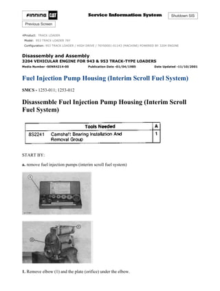
a. remove fuel injection pumps (interim scroll fuel system)
1. Remove elbow (1) and the plate (orifice) under the elbow.
1/6
953 TRACK LOADER / HIGH DRIVE / 76Y00001-01143 (MACHINE) POWERED ...
2021/12/26
https://127.0.0.1/sisweb/sisweb/techdoc/techdoc_print_page.jsp?returnurl=/sis...
2. 2. Remove rack (2) from the fuel injection pump housing.
NOTE: Spacers (3) are different thickness and are used to set the injection timing between
cylinders. Spacers (3) and lifters (4) must be installed in the same bore in the pump housing from
which they are removed. Put identification marks on the spacers and lifters as to their location in
the pump housing.
3. Remove spacers (3) and lifters (4) from the pump housing.
NOTE: The 943 lifters are made of aluminum. The 953 lifters are made of steel.
4. Remove bolt (5), the lock and plate (6) from the camshaft.
5. Remove spring (7) and gear (8) from the camshaft.
2/6
953 TRACK LOADER / HIGH DRIVE / 76Y00001-01143 (MACHINE) POWERED ...
2021/12/26
https://127.0.0.1/sisweb/sisweb/techdoc/techdoc_print_page.jsp?returnurl=/sis...
3. 6. Remove camshaft (10) from the pump housing.
7. Remove bearings (9) and (11) from the pump housing.
8. Use tooling (A) as shown to remove the bearings for the camshaft from the pump housing.
Assemble Fuel Injection Pump Housing (Interim Scroll Fuel
System)
NOTE: Be sure all oil passages in the pump housing are clear. Put clean oil on all parts before
assembly.
3/6
953 TRACK LOADER / HIGH DRIVE / 76Y00001-01143 (MACHINE) POWERED ...
2021/12/26
https://127.0.0.1/sisweb/sisweb/techdoc/techdoc_print_page.jsp?returnurl=/sis...
4. 1. Install the camshaft bearings in the fuel injection pump housing with tooling (A). Install the
bearing in the governor end of the housing so the lubrication hole in the bearing is in alignment
with the lubrication hole in the housing. Install the camshaft bearings so they are 0.25 ± 0.13 mm
(.010 ± .005 in.) below the ends of the pump housing.
NOTICE
Install the rack bearing in the governor end of the housing with the
small holes in the bearing parallel to the vertical centerline of the
pump.
2. Install the rack bearing in the governor end of the housing with tooling (B). Install the bearing
so it is 4.95 ± 0.13 mm (.195 ± .005 in.) below the face of the housing.
NOTICE
Tooling (C) must be used to install the rack bearing in the drive end of
the pump housing. This will put the tab on the bearing in its correct
position, and install the bearing to the correct depth.
3. Install the 5P1665 Plate [part of tooling (C)] on the pump housing. Use the 9S6329 Driver [part
of tooling (C)] to install the rack bearing in the drive end of the pump housing.
4/6
953 TRACK LOADER / HIGH DRIVE / 76Y00001-01143 (MACHINE) POWERED ...
2021/12/26
https://127.0.0.1/sisweb/sisweb/techdoc/techdoc_print_page.jsp?returnurl=/sis...
5. NOTICE
Use extra caution when camshaft (1) is installed in the pump housing to
prevent damage to the camshaft bearings.
4. Install camshaft (1) in the pump housing.
5. Put gear (3), spring (4) and plate (2) in position on the camshaft as shown. Install the lock and
bolt that hold plate (2) in place.
6. Install lifters (5) and the spacers in their original position in the pump housing. Install the lifters
with the pin in the lifter on the same side as the pin in the pump housing.
5/6
953 TRACK LOADER / HIGH DRIVE / 76Y00001-01143 (MACHINE) POWERED ...
2021/12/26
https://127.0.0.1/sisweb/sisweb/techdoc/techdoc_print_page.jsp?returnurl=/sis...
6. NOTE: If it is necessary to check the injection timing between cylinderse see Off-Engine Lifter
Setting procedure in Testing And Adjusting.
7. Install rack (6) in the pump housing with the groove near the end of the rack toward the
governor end of the pump housing.
8. Be sure the hole in plate (orifice) (7) is open, and install plate (7) in the pump housing. Install
the elbow over the plate.
END BY:
a. install fuel injection pumps (interim scroll fuel system)
Copyright 1993 - 2021 Caterpillar Inc.
All Rights Reserved.
Private Network For SIS Licensees.
Sun Dec 26 23:37:46 UTC+0800 2021
6/6
953 TRACK LOADER / HIGH DRIVE / 76Y00001-01143 (MACHINE) POWERED ...
2021/12/26
https://127.0.0.1/sisweb/sisweb/techdoc/techdoc_print_page.jsp?returnurl=/sis...
7. Shutdown SIS
Previous Screen
Product: TRACK LOADER
Model: 953 TRACK LOADER 76Y
Configuration: 953 TRACK LOADER / HIGH DRIVE / 76Y00001-01143 (MACHINE) POWERED BY 3204 ENGINE
Disassembly and Assembly
3204 VEHICULAR ENGINE FOR 943 & 953 TRACK-TYPE LOADERS
Media Number -SENR4214-00 Publication Date -01/04/1985 Date Updated -11/10/2001
Fuel Injection Pump Housing (New Scroll Fuel System
Effective In Production With 10X5411-Up, 45V36536-Up)
SMCS - 1253-015; 1253-016
Disassemble Fuel Injection Pump Housing (New Scroll Fuel
System Effective In Production With 10X5411-UP, 45V36536
-UP)
START BY:
a. remove governor from fuel injection pump housing (new scroll fuel system effective in
production with 10X5411-UP, 45V36536-UP)
1/10
953 TRACK LOADER / HIGH DRIVE / 76Y00001-01143 (MACHINE) POWERED ...
2021/12/26
https://127.0.0.1/sisweb/sisweb/techdoc/techdoc_print_page.jsp?returnurl=/sis...
8. 1. Remove cover (1).
2. Install tooling (B). Engage the timing pin in the center groove of the fuel rack. Move the fuel
rack in the direction of the arrow to find the center groove.
3. Install tooling (D), and remove bushing (2).
4. Install tooling (E), and remove the fuel injection pump.
5. Remove spacer (3).
NOTICE
Do not mix components from fuel injection pump assemblies.
2/10
953 TRACK LOADER / HIGH DRIVE / 76Y00001-01143 (MACHINE) POWERED ...
2021/12/26
https://127.0.0.1/sisweb/sisweb/techdoc/techdoc_print_page.jsp?returnurl=/sis...
9. 6. Remove the remainder of the fuel injection pumps and spacers with Steps 2-5 done again for
each fuel injection pump.
7. Remove cover (4).
8. Remove fuel rack (5).
9. Use a bar magnet to remove lifter assembly (6).
10. Use tooling (A) to remove snap ring (7).
3/10
953 TRACK LOADER / HIGH DRIVE / 76Y00001-01143 (MACHINE) POWERED ...
2021/12/26
https://127.0.0.1/sisweb/sisweb/techdoc/techdoc_print_page.jsp?returnurl=/sis...
10. 11. Use a plastic hammer to move camshaft (8) out of washer (9).
NOTICE
Do not let the camshaft fall because the machined surfaces will be
scratched.
12. Remove camshaft (8).
13. Remove rack rear bearing (10) and camshaft rear bearing (11).
4/10
953 TRACK LOADER / HIGH DRIVE / 76Y00001-01143 (MACHINE) POWERED ...
2021/12/26
https://127.0.0.1/sisweb/sisweb/techdoc/techdoc_print_page.jsp?returnurl=/sis...
11. 14. Install location plate from tooling (B). Align the bore in the plate with the O-ring seal
counterbore in the fuel injection pump housing. Make a mark for alignment.
15. Remove tooling (B).
16. Remove rack bearing (12) and camshaft bearing (13).
Assemble Fuel Injection Pump Housing (New Scroll Fuel
System Effective In Production With 10X5411-Up, 45V36536-
Up)
5/10
953 TRACK LOADER / HIGH DRIVE / 76Y00001-01143 (MACHINE) POWERED ...
2021/12/26
https://127.0.0.1/sisweb/sisweb/techdoc/techdoc_print_page.jsp?returnurl=/sis...
12. NOTE: Be sure all oil passages are clear, and put clean oil on all parts before assembly.
1. Use tool (A) to install the camshaft front bearing. Install the bearing with the joint toward the
top of the fuel injection pump housing. Install the bearing so it is 1.00 ± 0.25 mm (.039 ± .010 in.)
below the surface of the housing. The inside diameter of the bearing must be 55.090 ± 0.039 mm
(2.1688 ± .0015 in.) after assembly. Install the camshaft rear bearing with tooling (A). Install the
bearing with joint toward the top of the fuel injection pump housing. Install the bearing so it is
0.25 ± 0.20 mm (.0098 ± .0078 in.) below the surface of the housing. The inside diameter of the
bearing must be 68.339 ± 0.039 mm (2.6905 ± .0015 in.) after assembly.
2. Use tooling (A) to install the fuel rack rear (governor end) bearing. Install the bearing so it is
7.16 ± 0.13 mm (.282 ± .005 in.) below the surface of the housing.
6/10
953 TRACK LOADER / HIGH DRIVE / 76Y00001-01143 (MACHINE) POWERED ...
2021/12/26
https://127.0.0.1/sisweb/sisweb/techdoc/techdoc_print_page.jsp?returnurl=/sis...
13. 3. Install the locator plate from tooling (B) on the drive end of the fuel injection pump housing to
install the bearing for the fuel rack. Use clean grease to hold the new fuel rack bearing on the
driver from tooling (C). Install the driver and bearing in the plate with the groove in the driver in
alignment with the pin in the plate, and use a hammer to push the bearing into position. The
bearing will be installed to the correct depth when the shoulder of the driver is against the plate.
4. Remove tooling (B) from the fuel injection pump housing. The rack bearing must be installed
so it is 0.25 ± 0.25 mm (0.010 ± 0.010 in.) below the surface of the housing.
5. Install fuel injection pump camshaft (1) in the fuel injection pump housing.
6. Put the fuel injection pump housing on end, and put a block under the camshaft.
7. Put washer (2) over the end of the camshaft, and use tooling (A) and (C) to push washer (2)
against its seat on the camshaft. The camshaft must have 0.285 ± 0.235 mm (0.0112 ± 0.0093 in.)
end play when the washer is pushed against the cam shoulder.
7/10
953 TRACK LOADER / HIGH DRIVE / 76Y00001-01143 (MACHINE) POWERED ...
2021/12/26
https://127.0.0.1/sisweb/sisweb/techdoc/techdoc_print_page.jsp?returnurl=/sis...
14. 8. Use tool (D) to install snap ring (3) in the groove in the camshaft.
9. Install four lifter assemblies (4) in the fuel injection pump housing with the groove in the lifter
in alignment with the pin in the housing.
NOTE: The four lifters are all the same, and can be mixed.
10. Install fuel rack (5) in the fuel injection pump housing with the groove in the end of fuel rack
in alignment with the ear (tab) of the rack bearing at the drive end of the fuel injection pump
housing.
11. Install the timing pin from tooling (B). Engage the timing pin in the center groove of the fuel
rack. Move the fuel rack in the direction of the arrow to locate the center groove.
12. Install spacer (6).
8/10
953 TRACK LOADER / HIGH DRIVE / 76Y00001-01143 (MACHINE) POWERED ...
2021/12/26
https://127.0.0.1/sisweb/sisweb/techdoc/techdoc_print_page.jsp?returnurl=/sis...
15. 13. Put the (slot) groove (8) in the gear segment 180° away from groove (7) in the barrel. When
the fuel injection pump is installed, groove (7) must engage with dowel (9).
14. Use tool (E) to install the fuel injection pump. Installation is made easier by rotation of the
cam lobe away from the lifter assembly.
15. Install O-ring seal (10).
16. Install bushing (11). Tighten bushing (11) by hand until the bushing is even with the top of the
housing. If installation of the bushing can not be made this far by hand, remove it. Remove the
pump, put the parts in alignment again, and install the bushing again.
17. Use tool (F) and a torque wrench to tighten the bushing to a torque of 190 ± 14 N·m (140 ± 10
lb.ft.).
9/10
953 TRACK LOADER / HIGH DRIVE / 76Y00001-01143 (MACHINE) POWERED ...
2021/12/26
https://127.0.0.1/sisweb/sisweb/techdoc/techdoc_print_page.jsp?returnurl=/sis...
16. 18. Remove tooling (B).
19. Install tooling (G) and (H) to measure total rack travel. Correct rack travel is 15.70 mm (.618
in.). A smaller measurement is an indication of incorrect fuel injection pump installation.
20. Complete the installation of the remainder of fuel injection pumps as given in Steps 11-19.
21. Install cover and gasket (12).
END BY:
a. install governor on fuel injection pump housing (new scroll fuel system effective in production
with 10X5411-UP, 45V36536-UP)
Copyright 1993 - 2021 Caterpillar Inc.
All Rights Reserved.
Private Network For SIS Licensees.
Sun Dec 26 23:38:41 UTC+0800 2021
10/10
953 TRACK LOADER / HIGH DRIVE / 76Y00001-01143 (MACHINE) POWERE...
2021/12/26
https://127.0.0.1/sisweb/sisweb/techdoc/techdoc_print_page.jsp?returnurl=/sis...
17. Shutdown SIS
Previous Screen
Product: TRACK LOADER
Model: 953 TRACK LOADER 76Y
Configuration: 953 TRACK LOADER / HIGH DRIVE / 76Y00001-01143 (MACHINE) POWERED BY 3204 ENGINE
Disassembly and Assembly
3204 VEHICULAR ENGINE FOR 943 & 953 TRACK-TYPE LOADERS
Media Number -SENR4214-00 Publication Date -01/04/1985 Date Updated -11/10/2001
Oil Filter Bypass Valve
SMCS - 1314-010
Remove And Install Oil Filter Bypass Valve
NOTE: The tool box was removed for photo purposes only.
1. Remove plug (1), the spring and oil filter bypass valve.
2. Be sure the O-ring seal is in position on plug (1), and put clean oil on the O-ring seal.
3. Install oil filter bypass valve (2), spring (3) and the plug in the oil filter base.
Copyright 1993 - 2021 Caterpillar Inc.
All Rights Reserved.
Private Network For SIS Licensees.
Sun Dec 26 23:39:37 UTC+0800 2021
1/1
953 TRACK LOADER / HIGH DRIVE / 76Y00001-01143 (MACHINE) POWERED ...
2021/12/26
https://127.0.0.1/sisweb/sisweb/techdoc/techdoc_print_page.jsp?returnurl=/sis...
18. Shutdown SIS
Previous Screen
Product: TRACK LOADER
Model: 953 TRACK LOADER 76Y
Configuration: 953 TRACK LOADER / HIGH DRIVE / 76Y00001-01143 (MACHINE) POWERED BY 3204 ENGINE
Disassembly and Assembly
3204 VEHICULAR ENGINE FOR 943 & 953 TRACK-TYPE LOADERS
Media Number -SENR4214-00 Publication Date -01/04/1985 Date Updated -11/10/2001
Engine Oil Cooler (Earlier 943)
SMCS - 1378-011; 1378-012
Remove Engine Oil Cooler (Earlier 943)
NOTE: The radiator guard and engine enclosure were removed for better photo illustration only.
1. Close fuel valve (1) on the fuel tank.
2. Disconnect the wires from fuel pressure switch (2) on the fuel filter base.
NOTE: Put plugs or caps on all fuel line openings when the fuel lines are removed.
3. Remove fuel lines (3) and (4).
1/4
953 TRACK LOADER / HIGH DRIVE / 76Y00001-01143 (MACHINE) POWERED ...
2021/12/26
https://127.0.0.1/sisweb/sisweb/techdoc/techdoc_print_page.jsp?returnurl=/sis...
19. 4. Remove fuel lines (5) and (6).
5. Remove four bolts (7), and remove bracket (8) and the fuel filter base. Move plate (9) and the
fuel lines clear of the engine.
6. Drain the coolant from the engine.
7. Loosen hose clamp (10), and disconnect the hose from the fitting in the cylinder block.
8. Remove bolts (11), and slide engine oil cooler (12) off sleeve (13) to remove it.
9. Put alignment marks on bonnets (14), (15) and the cooler core so the bonnets will be installed in
the correct position. Remove bonnets (14) and (15) from the cooler core.
2/4
953 TRACK LOADER / HIGH DRIVE / 76Y00001-01143 (MACHINE) POWERED ...
2021/12/26
https://127.0.0.1/sisweb/sisweb/techdoc/techdoc_print_page.jsp?returnurl=/sis...
20. Install Engine Oil Cooler (Earlier 943)
1. Use an acceptable rod to clean the tubes in core (1) for the engine oil cooler.
2. Install the bonnets on core (1) in the correct position.
3. Be sure O-ring seals (2) are in position on the oil manifold.
4. Put clean oil on the O-ring seal on sleeve (3). Put the engine oil cooler in position on sleeve (3)
and the oil manifold. Install the two bolts that hold the engine oil cooler in place. Connect hose (4)
to the fitting in the block, and tighten the hose clamp.
5. Fill the engine with coolant to the correct level. See the Maintenance Guide.
3/4
953 TRACK LOADER / HIGH DRIVE / 76Y00001-01143 (MACHINE) POWERED ...
2021/12/26
https://127.0.0.1/sisweb/sisweb/techdoc/techdoc_print_page.jsp?returnurl=/sis...
21. 6. Put plate (5) and bracket (6) and the fuel filter base in position on the engine oil cooler. Install
the four bolts that hold them in place.
7. Install fuel lines (7) and (9).
8. Connect the two wires to fuel pressure switch (8) on the fuel filter base.
9. Open the fuel valve on the fuel tank.
10. Prime the fuel system. See Priming Fuel System in the Maintenance Guide.
Copyright 1993 - 2021 Caterpillar Inc.
All Rights Reserved.
Private Network For SIS Licensees.
Sun Dec 26 23:40:33 UTC+0800 2021
4/4
953 TRACK LOADER / HIGH DRIVE / 76Y00001-01143 (MACHINE) POWERED ...
2021/12/26
https://127.0.0.1/sisweb/sisweb/techdoc/techdoc_print_page.jsp?returnurl=/sis...
22. Shutdown SIS
Previous Screen
Product: TRACK LOADER
Model: 953 TRACK LOADER 76Y
Configuration: 953 TRACK LOADER / HIGH DRIVE / 76Y00001-01143 (MACHINE) POWERED BY 3204 ENGINE
Disassembly and Assembly
3204 VEHICULAR ENGINE FOR 943 & 953 TRACK-TYPE LOADERS
Media Number -SENR4214-00 Publication Date -01/04/1985 Date Updated -11/10/2001
Engine Oil Cooler (953 & Later 943)
SMCS - 1378-012; 1378-011
Remove Engine Oil Cooler (953 & Later 943)
NOTE: The radiator guard and engine enclosure were removed for better photo illustration only.
1. Close the fuel valve on the fuel tank. Drain the coolant from the engine.
2. Disconnect the wires from fuel pressure switch (1) on the fuel filter base.
NOTE: Put plugs or caps on all fuel line openings when the fuel lines are disconnected.
3. Remove fuel lines (2) and (3).
4. Remove fuel lines (4) and (5).
1/5
953 TRACK LOADER / HIGH DRIVE / 76Y00001-01143 (MACHINE) POWERED ...
2021/12/26
https://127.0.0.1/sisweb/sisweb/techdoc/techdoc_print_page.jsp?returnurl=/sis...
23. 5. Remove water line (6) from the oil cooler and the elbow on the timing gear cover.
6. Remove two bolts (8) and bracket (7) from the oil manifold. Move the bracket clear of the oil
cooler.
7. Loosen hose clamp (9), and disconnect the water line from cover (11).
8. Remove 10 bolts (10), and remove cover (11) and the core assembly as a unit from the oil
manifold.
9. Remove cover (11) from the core assembly.
2/5
953 TRACK LOADER / HIGH DRIVE / 76Y00001-01143 (MACHINE) POWERED ...
2021/12/26
https://127.0.0.1/sisweb/sisweb/techdoc/techdoc_print_page.jsp?returnurl=/sis...
24. 10. Carefully lift out each side of divider (12); then slide it out from between the plates of the
core.
Install Engine Oil Cooler (953 & Later 943)
1. Install the divider between the fifth and sixth plates from the flange and on the end opposite
from hole (2) in the flange as shown. Hole (2) does not have the same spacing as the other holes.
Install the divider with boss (1) on the divider in the relation shown to hole (2). The divider must
be installed evenly around the circumference of the plates so the cover will make a seal correctly
when it is installed.
2. Install the gasket and cover (3) on the core as shown.
3. Put the gasket, oil cooler core and cover (3) in position on the oil manifold. Install the bolts that
hold it in place, and connect water line (4) to the cover.
3/5
953 TRACK LOADER / HIGH DRIVE / 76Y00001-01143 (MACHINE) POWERED ...
2021/12/26
https://127.0.0.1/sisweb/sisweb/techdoc/techdoc_print_page.jsp?returnurl=/sis...
25. 4. Put bracket (5) in position on the oil manifold, and install the two bolts that hold it in place.
5. Install water line (6) as shown.
6. Install fuel lines (7) and (8).
7. Install fuel lines (9) and (10).
8. Connect the two wires to fuel pressure switch (11).
9. Fill the engine to the correct level with coolant. See the Maintenance Guide.
10. Open the fuel valve on the fuel tank.
11. Prime the fuel system. See Priming Fuel System in the Maintenance Guide.
4/5
953 TRACK LOADER / HIGH DRIVE / 76Y00001-01143 (MACHINE) POWERED ...
2021/12/26
https://127.0.0.1/sisweb/sisweb/techdoc/techdoc_print_page.jsp?returnurl=/sis...
26. Copyright 1993 - 2021 Caterpillar Inc.
All Rights Reserved.
Private Network For SIS Licensees.
Sun Dec 26 23:41:29 UTC+0800 2021
5/5
953 TRACK LOADER / HIGH DRIVE / 76Y00001-01143 (MACHINE) POWERED ...
2021/12/26
https://127.0.0.1/sisweb/sisweb/techdoc/techdoc_print_page.jsp?returnurl=/sis...
27. Shutdown SIS
Previous Screen
Product: TRACK LOADER
Model: 953 TRACK LOADER 76Y
Configuration: 953 TRACK LOADER / HIGH DRIVE / 76Y00001-01143 (MACHINE) POWERED BY 3204 ENGINE
Disassembly and Assembly
3204 VEHICULAR ENGINE FOR 943 & 953 TRACK-TYPE LOADERS
Media Number -SENR4214-00 Publication Date -01/04/1985 Date Updated -11/10/2001
Oil Pan
SMCS - 1302-012; 1302-011
Remove Oil Pan
1. Remove the guard below the engine. Weight is approximately 66 kg (146 lb.).
2. Remove drain plug (2), and drain the oil from the oil pan.
3. Remove the oil level gauge from the engine.
4. Remove 28 bolts (1) that hold oil pan (3) in place, and remove the oil pan.
5. Remove bolts (5) that hold suction tube (4) in place, and remove the suction tube.
Install Oil Pan
1/2
953 TRACK LOADER / HIGH DRIVE / 76Y00001-01143 (MACHINE) POWERED ...
2021/12/26
https://127.0.0.1/sisweb/sisweb/techdoc/techdoc_print_page.jsp?returnurl=/sis...
28. 1. Put suction tube (1) in position on the oil pump cover, and install the two bolts that hold it in
place. Install the bolt that holds clip (2) to the cylinder block.
2. Inspect the oil pan gasket, and install a new gasket if needed.
3. Put oil pan (3) in position on the engine, and install the 28 bolts that hold it in place.
4. Install the oil level gauge.
5. Tighten drain plug (4) to a torque of 54 ± 6 N·m (40 ± 4 lb.ft.).
6. Fill the engine with oil to the correct level. See the Maintenance Guide.
7. Install the guard below the engine.
Copyright 1993 - 2021 Caterpillar Inc.
All Rights Reserved.
Private Network For SIS Licensees.
Sun Dec 26 23:42:24 UTC+0800 2021
2/2
953 TRACK LOADER / HIGH DRIVE / 76Y00001-01143 (MACHINE) POWERED ...
2021/12/26
https://127.0.0.1/sisweb/sisweb/techdoc/techdoc_print_page.jsp?returnurl=/sis...
29. Please write to us.
Our email:
aservicemanualpdf@yahoo.com
Please go to the homepage
to get the full manual, or
other brand PDF manuals.
Home Site:
aservicemanualpdf.com
30. Thank you very much for
your reading. Please Click
Here. Then Get COMPLETE
MANUAL. NO WAITING
NOTE:
If there is no response to
click on the link above,
please download the PDF
document first and then
click on it.
GET MORE OTHER MANUALS https://www.aservicemanualpdf.com/
GET MORE OTHER MANUALS https://www.aservicemanualpdf.com/
31. Shutdown SIS
Previous Screen
Product: TRACK LOADER
Model: 953 TRACK LOADER 76Y
Configuration: 953 TRACK LOADER / HIGH DRIVE / 76Y00001-01143 (MACHINE) POWERED BY 3204 ENGINE
Disassembly and Assembly
3204 VEHICULAR ENGINE FOR 943 & 953 TRACK-TYPE LOADERS
Media Number -SENR4214-00 Publication Date -01/04/1985 Date Updated -11/10/2001
Oil Pump And Relief Valve
SMCS - 1304-012; 1315-011
Remove Oil Pump And Relief Valve
START BY:
a. remove timing gear cover
1. Remove bolt (2) and the clip.
2. Remove sleeve (3) and guide assembly (1).
NOTE: If the valve assembly will not come out after the clip is removed, hit guide assembly (1)
with a plastic hammer to loosen it.
3. Remove plunger (4) and spring (5) from guide (6).
1/5
953 TRACK LOADER / HIGH DRIVE / 76Y00001-01143 (MACHINE) POWERED ...
2021/12/26
https://127.0.0.1/sisweb/sisweb/techdoc/techdoc_print_page.jsp?returnurl=/sis...
32. 4. Remove bolts (8) and cover (7).
5. Remove inner rotor (10) and outer rotor (9). The bearing in the inner rotor is not serviceable,
and the rotors must be replaced as a set.
6. Remove bearing (11) from the timing gear cover.
Install Oil Pump And Relief Valve
NOTICE
Replacement of rotors must be made as a set.
2/5
953 TRACK LOADER / HIGH DRIVE / 76Y00001-01143 (MACHINE) POWERED ...
2021/12/26
https://127.0.0.1/sisweb/sisweb/techdoc/techdoc_print_page.jsp?returnurl=/sis...
33. 1. If shaft (2) was removed from the timing gear cover, it must be installed to dimension (Y)
which is 21.84 ± 0.25 mm (.860 ± .010 in.) from the end of the shaft to the bottom face of the
counterbore in the cover.
2. Install bearing (1) in the timing gear cover to dimension (X) which is 8.74 ± 0.25 mm (.344
± .010 in.). The bearing joint must be located 45° ± 30° from plane (Z). Use tool (A) to install
bearing (1).
3/5
953 TRACK LOADER / HIGH DRIVE / 76Y00001-01143 (MACHINE) POWERED ...
2021/12/26
https://127.0.0.1/sisweb/sisweb/techdoc/techdoc_print_page.jsp?returnurl=/sis...