
Recommended
Recommended
More Related Content
What's hot
What's hot (20)
Similar to 2008 toyota prius service repair manual
Similar to 2008 toyota prius service repair manual (14)
More from fjjskejdmdn
More from fjjskejdmdn (20)
Recently uploaded
Recently uploaded (20)
2008 toyota prius service repair manual
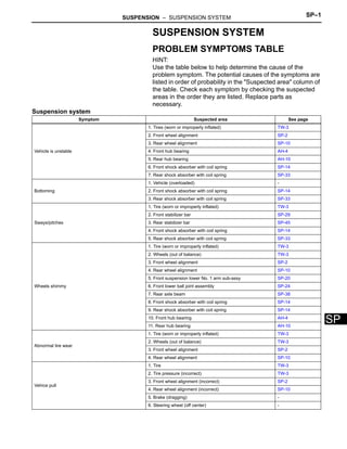
- 1. SUSPENSION – SUSPENSION SYSTEM SP–1 SP SUSPENSION SYSTEM PROBLEM SYMPTOMS TABLE HINT: Use the table below to help determine the cause of the problem symptom. The potential causes of the symptoms are listed in order of probability in the "Suspected area" column of the table. Check each symptom by checking the suspected areas in the order they are listed. Replace parts as necessary. Suspension system Symptom Suspected area See page Vehicle is unstable 1. Tires (worn or improperly inflated) TW-3 2. Front wheel alignment SP-2 3. Rear wheel alignment SP-10 4. Front hub bearing AH-4 5. Rear hub bearing AH-10 6. Front shock absorber with coil spring SP-14 7. Rear shock absorber with coil spring SP-33 Bottoming 1. Vehicle (overloaded) - 2. Front shock absorber with coil spring SP-14 3. Rear shock absorber with coil spring SP-33 Sways/pitches 1. Tire (worn or improperly inflated) TW-3 2. Front stabilizer bar SP-29 3. Rear stabilizer bar SP-45 4. Front shock absorber with coil spring SP-14 5. Rear shock absorber with coil spring SP-33 Wheels shimmy 1. Tire (worn or improperly inflated) TW-3 2. Wheels (out of balance) TW-3 3. Front wheel alignment SP-2 4. Rear wheel alignment SP-10 5. Front suspension lower No. 1 arm sub-assy SP-20 6. Front lower ball joint assembly SP-24 7. Rear axle beam SP-38 8. Front shock absorber with coil spring SP-14 9. Rear shock absorber with coil spring SP-14 10. Front hub bearing AH-4 11. Rear hub bearing AH-10 Abnormal tire wear 1. Tire (worn or improperly inflated) TW-3 2. Wheels (out of balance) TW-3 3. Front wheel alignment SP-2 4. Rear wheel alignment SP-10 Vehice pull 1. Tire TW-3 2. Tire pressure (incorrect) TW-3 3. Front wheel alignment (incorrect) SP-2 4. Rear wheel alignment (incorrect) SP-10 5. Brake (dragging) - 6. Steering wheel (off center) -
- 2. SP–2 SUSPENSION – FRONT WHEEL ALIGNMENT SP FRONT WHEEL ALIGNMENT ADJUSTMENT 1. INSPECT TIRE (a) Inspect the tires (see page TW-3). 2. MEASURE VEHICLE HEIGHT Standard vehicle height Measuring points: A: Ground clearance of front wheel center B: Ground clearance of lower arm No. 1 set bolt center C: Ground clearance of rear axle carrier bush set bolt center D: Ground clearance of rear wheel center NOTICE: Before inspecting the wheel alignment, adjust the vehicle height to the specified value. HINT: Bounce the vehicle at the corners up and down to stabilize the suspension and inspect the vehicle height. 3. INSPECT TOE-IN Standard toe-in HINT: • Measure "C - D" only when "A + B" cannot be measured. • If the toe-in is not within the specified range, adjust it at the rack ends. 4. ADJUST TOE-IN (a) Measure the thread lengths of the right and left rack ends. Standard difference in thread length: 1.5 mm (0.059 in.) or less (b) Remove the rack boot set clips. (c) Loosen the tie rod end lock nuts. (d) Adjust the rack ends if the difference in thread length between the right and left rack ends is not within the specified range. (1) Extend the shorter rack end if the measured toe-in deviates toward the outer-side. (2) Shorten the longer rack end if the measured toe-in deviates toward the inner-side. A D C B Front: Rear: F046082E03 Item Specified Condition Front (A - B) 95 mm (3.74 in.) Rear (D - C) 62 mm (2.44 in.) A B D Front C SA03213E02 Item Specified Condition Toe-in (total) A + B: 0° +-12' (0° +-0.2°) C - D: 0 +-2 mm (0 +-0.08 in.)
- 3. SUSPENSION – FRONT WHEEL ALIGNMENT SP–3 SP (e) Turn the right and left rack ends by an equal amount to adjust toe-in. HINT: Try to adjust toe-in to the center of the specified range. (f) Make sure that the lengths of the right and left rack ends are the same. Standard : 0 +-1 mm (0.0039 in.) (g) Torque the tie rod end lock nuts. Torque: 74 N*m (755 kgf*cm, 55 ft.*lbf) NOTICE: Temporarily tighten the lock nut while holding the hexagonal part of the steering rack end so that the lock nut and the steering rack end do not turn together. Hold the width across the flat part of the tie rod end and tighten the lock nut. (h) Place the boots on the seats and install the clips. HINT: Make sure that the boots are not twisted. (i) Perform VSC system calibration (see page BC-21). 5. INSPECT WHEEL ANGLE (a) Fully turn the steering wheel to the left and right and measure the turning angle. Standard wheel turning angle If the right and left inside wheel angles differ from the specified range, check the right and left rack end lengths. 6. INSPECT CAMBER, CASTER AND STEERING AXIS INCLINATION (a) Put the front wheel on the center of the alignment tester. (b) Remove the center ornament. (c) Install the camber-caster-steering axis inclination gauge at the center of the axle hub or drive shaft. (d) Inspect the camber, caster and steering axis inclination. Standard camber, caster and steering axis inclination Lock Nut Difference F046085E01 A: Inside B: Outside Front A B A B Front C118572E01 Item Specified Condition Inside wheel 40° 35' +-2° (40.58° +-2°) Outside wheel: Reference 34° 15' (34.25°) Gauge Alignment Tester Z003382E08 Item Specified Condition Camber Right-left error -0° 35' +-45' (-0.58° +-0.75°) 45' (0.75°) or less Caster Right-left error 3° 10' +-45' (3.17° +-0.75°) 45' (0.75°) or less
- 4. SP–4 SUSPENSION – FRONT WHEEL ALIGNMENT SP NOTICE: • Inspect with an empty vehicle (without the spare tire or tools). • The maximum tolerance of the right and left difference for the camber and caster is 45' or less. (e) Remove the camber-caster-steering axis inclination gauge and attachment. (f) Install the center ornament. If the caster and steering axis inclination are not within the specified values after the camber has been correctly adjusted, recheck the suspension parts for damage and/or wear. 7. ADJUST CAMBER NOTICE: Inspect toe-in after the camber has been adjusted. (a) Remove the front wheel. (b) Remove the 2 nuts on the lower side of the shock absorber. NOTICE: When removing the nut, stop the bolt from rotating and loosen the nut. (c) Clean the installation surfaces of the shock absorber and the steering knuckle. (d) Temporarily install the 2 nuts. (e) Fully push or pull the front axle hub in the direction of the required adjustment. (f) Tighten the nuts. Torque: 153 N*m (1,560 kgf*cm, 113 ft.*lbf) NOTICE: Keep the bolts from rotating and torque the nuts. (g) Install the front wheel. Torque: 103 N*m (1,050 kgf*cm, 76 ft.*lbf) (h) Check the camber. If the measured value is not within the specified range, calculate the required adjustment amount using the formula below. Camber adjustment amount: Center of the specified range - Measured value Check the installed bolt combination. Select appropriate bolts from the table below to adjust the camber to within the specified range. Standard selection table Steering axis inclination Right-left error 12° 35' +-45' (12.58° +-0.75°) 45' (0.75°) or less Item Specified Condition F046086E01 + - F047225E02 1 2 F047338E01 Item Selection Table Move the axle toward (+) in step (e) Refer to table (1) (Move the axle toward positive side) Move the axle toward (-) in step (e) Refer to table (2) (Move the axle toward negative side)
- 5. SUSPENSION – FRONT WHEEL ALIGNMENT SP–5 SP (i) Measure the camber with the bolts currently installed and check the amount of looseness from the specified range. (Ex: The measured value is - 1°35') (j) Determine whether the direction of the required adjustment is toward the positive or negative side. (Ex: Refer to table (1) (Move the axle toward positive side)) (k) Check the required adjustment amount from the measured value. (Table (1), Table (2)) (Ex: Select "Adjust value: 0°45' to 1°00") (l) Check the currently installed bolt combination. (Ex: " Installed bolt 1: no dot; Installed bolt 2: 2 dots") (m) Select the adjusting bolts. (Ex: "Selected Bolt Combination" results in F for installed bolt 1: 3 dots; Installed bolt 2: 3 dots) (n) Measure the alignment again and check that it is within the specified range. (Ex: Measured value is within -0° 35' +-45')
- 6. SP–6 SUSPENSION – FRONT WHEEL ALIGNMENT SP The body and suspension may be damaged if the camber is not correctly adjusted according to the above table. Table (1) (Move the axle toward positive side) Selected Bolt Combination Bolt Distinguishing Mark C125767E02
- 7. SUSPENSION – FRONT WHEEL ALIGNMENT SP–7 SP NOTICE: Replace the nut with a new one when replacing the bolt. (o) Repeat the steps mentioned above. At step (b), replace 1 or 2 selected bolts. HINT: Replace 1 bolt at a time when replacing 2 bolts.
- 8. SP–8 SUSPENSION – FRONT WHEEL ALIGNMENT SP The body and suspension may be damaged if the camber is not correctly adjusted according to the above table. (p) Repeat the steps mentioned above. At step (b), replace 1 or 2 selected bolts. Table (2) (Move the axle toward negative side) Selected Bolt Combination Bolt Distinguishing Mark C125768E02
- 9. SUSPENSION – FRONT WHEEL ALIGNMENT SP–9 SP NOTICE: Replace the nut with a new one when replacing the bolt. HINT: Replace 1 bolt at a time when replacing 2 bolts.
- 10. SP–10 SUSPENSION – REAR WHEEL ALIGNMENT SP REAR WHEEL ALIGNMENT INSPECTION 1. INSPECT TIRE (a) Inspect the tires (see page TW-3). 2. MEASURE VEHICLE HEIGHT (a) Measure the vehicle height (see page SP-2). 3. INSPECT TOE-IN Standard toe-in HINT: • Measure "C - D" only when "A + B'" cannot be measured. • If the toe-in is not within the specified range, inspect the suspension parts for damage and/or wear, and replace them if necessary. 4. INSPECT CAMBER (a) Install the camber-caster-kingpin gauge or set the vehicle on a wheel alignment tester. (b) Inspect the camber. Standard camber HINT: Camber is not adjustable. If the measurement is not within the specified range, inspect the suspension parts for damage and/or wear, and replace them if necessary. A B D Front C SA03213E02 Item Specified Condition Toe-in (total) A + B: 0° 18' +-15' (0.30° +-0.25°) C - D: 3.0 +-2.5 mm (0.12 +-0.10 in.) Item Specified Condition Camber Right-left error -1° 30' +-30' (-1.50 +-0.5°) 30' (0.5°) or less
- 11. SUSPENSION – FRONT SHOCK ABSORBER WITH COIL SPRING SP–11 SP SUSPENSION & AXLE SUSPENSION FRONT SHOCK ABSORBER WITH COIL SPRING COMPONENTS N*m (kgf*cm, ft.*lbf) : Specified torque Non-reusable part 19 (192, 14) FRONT COIL SPRING INSULATOR LOWER LH FRONT COIL SPRING INSULATOR UPPER LH FRONT COIL SPRING LH FRONT COIL SPRING SEAT UPPER LH FRONT SHOCK ABSORBER ASSEMBLY LH FRONT SHOCK ABSORBER WITH COIL SPRING FRONT SPRING BUMPER LH FRONT STABILIZER LINK ASSEMBLY LH FRONT SUSPENSION SUPPORT LH DUST SEAL FRONT SUSPENSION SUPPORT SUB-ASSEMBLY LH FRONT SPEED SENSOR LH 153 (1,560, 113) 74 (755, 55) 47 (479, 35) FRONT SUSPENSION SUPPORT DUST COVER LH 39 (398, 29) C129239E02
- 12. SP–12 SUSPENSION – FRONT SHOCK ABSORBER WITH COIL SPRING SP REMOVAL HINT: • Use the same procedures for the RH side and LH side. • The procedures listed below are for the LH side. 1. REMOVE FRONT WHEEL 2. REMOVE FRONT WIPER ARM HEAD CAP 3. REMOVE FRONT WIPER ARM LH (See page WW-13) 4. REMOVE FRONT WIPER ARM RH (See page WW-13) 5. REMOVE HOOD TO COWL TOP SEAL (See page WW-13) 6. REMOVE COWL TOP VENTILATOR LOUVER LH (See page WW-13) 7. REMOVE COWL TOP VENTILATOR LOUVER RH (See page WW-13) 8. REMOVE WINDSHIELD WIPER MOTOR AND LINK (See page WW-13) 9. DISCONNECT FRONT STABILIZER LINK ASSEMBLY (a) Place a wooden block on a jack, and support the front suspension lower No. 1 arm with the jack. (b) Remove the nut and separate the front stabilizer link from the shock absorber with coil spring. HINT: Use a 6 mm hexagon wrench to hold the stud if the ball joint turns together with the nut. 10. REMOVE FRONT SHOCK ABSORBER WITH COIL SPRING (a) Remove the bolt and disconnect the front flexible hose No. 1 and speed sensor front LH wire harness. NOTICE: Be sure to completely disconnect the speed sensor front LH from the front shock absorber. (b) Remove the 2 nuts on the lower side of the front shock absorber with coil spring. NOTICE: Keep the bolts inserted. F046088E01 C080880E01 F046086E01
- 13. Thank you very much for your reading. Please Click Here. Then Get COMPLETE MANUAL. NO WAITING NOTE: If there is no response to click on the link above, please download the PDF document first and then click on it.
- 14. SUSPENSION – FRONT SHOCK ABSORBER WITH COIL SPRING SP–13 SP (c) Remove the 3 nuts. (d) Lower the jack slowly. Remove the 2 bolts on the lower side and the front shock absorber with coil spring. NOTICE: Ensure that the speed sensor front LH is completely disconnected from the front shock absorber with coil spring. DISASSEMBLY 1. FIX FRONT SHOCK ABSORBER WITH COIL SPRING (a) Secure the front shock absorber with coil spring in a vise by clamping onto a double nutted bolt affixed to the bracket at the bottom of the absorber, as shown in the illustration to the left. 2. REMOVE FRONT SUPPORT TO FRONT SHOCK ABSORBER LH NUT (a) Attach SST to the coil spring so that the upper and lower hooks of the installed area are as wide as possible. SST 09727-30021 (09727-00010, 09727-00021, 09727-00031) (b) Fully compress the coil spring. NOTICE: Do not use an impact wrench. It will damage SST. HINT: The coil spring can also be installed/removed using the hydraulic spring compressor. (c) Remove the front suspension support dust cover. (d) Secure the front coil spring seat upper with SST and remove the front suspension support to front shock absorber LH nut. SST 09729-22031 3. REMOVE FRONT SUSPENSION SUPPORT SUB- ASSEMBLY LH 4. REMOVE FRONT SUSPENSION SUPPORT LH DUST SEAL 5. REMOVE FRONT COIL SPRING SEAT UPPER LH 6. REMOVE FRONT COIL SPRING INSULATOR UPPER LH 7. REMOVE FRONT COIL SPRING LH 8. REMOVE FRONT SPRING BUMPER LH F046083E01 40 mm (1.57 in.) F047339E02 SST F047340E01 SST F047341E01
- 15. SP–14 SUSPENSION – FRONT SHOCK ABSORBER WITH COIL SPRING SP 9. REMOVE FRONT COIL SPRING INSULATOR LOWER LH 10. REMOVE FRONT SHOCK ABSORBER ASSEMBLY LH INSPECTION 1. INSPECT FRONT SHOCK ABSORBER ASSEMBLY LH (a) Compress and extend the shock absorber rod 4 or more times. Check that there is no abnormal resistance or sound. If there is any abnormality, replace the shock absorber front LH with a new one. NOTICE: When disposing of the shock absorber, see DISPOSAL (see page SP-17). C066739E01