
Recommended
Recommended
More Related Content
More from fiskefjskemem
More from fiskefjskemem (20)
Recently uploaded
Recently uploaded (20)
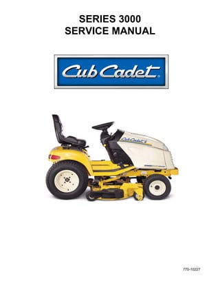
Cub cadet 3205 tractor service repair manual
- 2. Series 3000 Technical Handbook Table of Contents Section Pre-Delivery Check List and Service Specifications 1999 ................................................................................1 Engineering Updates 1999................................................................................................................................2 Fender Removal and Reinstallation ..................................................................................................................3 Hydraulic Step by Step Flow Charts .................................................................................................................4 Power Steering Cylinder Removal and Replacement .......................................................................................5 Power Steering Pump Disassemble, Inspect and Reassemble ........................................................................6 Center Lift Cylinder Removal and Replacement ...............................................................................................7 Pump Adapter Removal and Replacement.......................................................................................................8 BDU-21L-500 Pressure Test Procedure ...........................................................................................................9 Hydraulic Steering Pump Removal and Replacement ....................................................................................10 Hydraulic Valve Removal and Replacement...................................................................................................11 Engine Removal and Replacement.................................................................................................................12 Transmission Removal and Installation ..........................................................................................................13 Transmission Inspection and Disassembly .....................................................................................................14 Transmission Reassembly (Cast Iron Transmission Addendum)...................................................................15 Neutral Control Adjustment .............................................................................................................................16 3000 Series Electrical .....................................................................................................................................17 BDU-21L Transmission ...................................................................................................................................18
- 3. 2 - 1 Cub Cadet 3000 1999 3000 Series Engineering Updates 1. Remove both of the hex bolts and lock nuts securing the front bumper to the frame using a 3/4" socket and a 3/4" wrench. 2. Remove the bumper. 3. Slide the muffler shield over the exhaust pipe and rotate it into position. NOTE: Align all three holes in the top of the muffler shield with the existing shield. Also, the muffler shield will be slanting towards the bottom of the front grill assembly. Heat Shield Heat Shield HEAT SHIELD A heat shield has been installed on all 3000 series tractors for 1999. The heat shield prevents the exhaust gases from browning the grass. Use kit #759- 3927. See Service Advisory CC-371. LIFT LINK The lift link has been modified by strengthening the powder metal that connects the lift lever to the hydraulic valve for 1999. CHECK VALVE For 1999, a check valve will be installed to the hydraulic valve to prevent the decks and other attach- ments from leaking down during and after usage. LIFT STOP BRACKET A lift stop bracket will be installed on the left hand side of the deck to prevent the deck from hanging up dur- ing operations. Use kit #759-3927. ROLLER HEIGHT ADJUSTER The rear roller height adjustment mechanism will be changed for 1999. A newly designed detent pin will replace the old one, preventing the loss of cutting height during operations. Use kit #759-3928. FRONT DECK HANGER ASSEMBLY The front roller bracket has been redesigned to pre- vent the front lift rod from detaching during operation. SEAT IMPROVEMENTS A safer seat spring, part number 732-0869, can be installed to level the seat for petite operators. In addi- tion, the seat part number 757-3010A, is now made out of a softer material for better operator comfort. See Service Advisory CC-358A Sections 5 and 6. FRONT MOWER DECK HEIGHT ADJUSTER The front mower deck height adjuster pins have been changed from ball detent pins to quick pull pins. Sheet Metal Screws Screwdriver Grill Mark used in Production to Test PTO Activation 4. Secure the muffler shield with three sheet metal screws. NOTE: Use a long flat blade screwdriver through the air holes in the grill to tighten the sheet metal screws securely. 5. Install the bumper.
- 4. 2 - 2 Cub Cadet 3000 STEERING WHEEL The thickness of the steering wheel has been increased for operator comfort. New Thicker Steering Wheel Steering Wheel Thicker Old Style Steering Wheel Steering Wheel Thinner ROCK SHAFT ASSEMBLY FOR 3 POINT HITCH 190-365-100 The cylinder arms have been redesigned with two V sections cut out to allow for clearance of the clevis nut on the cylinder shaft. See Service Advisory CC-364. 3000 Series Lift Assembly Grooved Out Area
- 5. 2 - 3 Cub Cadet 3000
- 6. 2 - 4 Cub Cadet 3000
- 7. 2 - 5 Cub Cadet 3000
- 8. 2 - 6 Cub Cadet 3000
- 9. 2 - 7 Cub Cadet 3000
- 10. NOTES
- 11. 3 - 1 Cub Cadet 3000 1. Slide the seat back and remove the front two pan torx head screws using a T30 torx. 2. Slide the seat forward and remove the rear two pan torx head screws using a T30 torx. 3. Pivot the seat assembly to the side and disconnect the seat safety switch. See figure 1. NOTE: Be careful not to scratch the fender with the seat support brackets. It is advisable to use a towel or cloth under the seat when pivoting the seat. 4. Remove the seat from the tractor. See figure 1. 5. Remove all the hex bolts securing the three foot pedals to the right side of the unit using a 9/16 socket. See figure 2. Fender Assembly Removal and Reinstallation FIGURE 1. Torx Screws Seat Safety Switch FIGURE 2. Hex Bolts Hex Bolts Reverse Pedal Forward Pedal Brake Pedal FIGURE 3. Hex Bolt Differential Lock Out Pedal Nylon Flange Bearing E-Clip 6. Remove the hex bolt securing the differential lock out pedal on the left side of the unit using a 9/16 socket. Remove the “E” clip and the nylon flange bearing from the pivot shaft. FIGURE 4. Wing Nut Side Panel Latch Dash Screen Side Panel Latch Rubber Foot Pads 7. Remove both rubber floor pads from the running boards. See figure 4. 8. Lift the hood and remove the battery cover. 9. Remove both side panels from the tractor by raising the latches horizontally and turning the latches 1/4 turn. See figure 4. 10. Loosen all four plastic wing nuts holding the dash panel screen in place. See figure 4. 11. Pull the dash screen towards the rear of the unit and out of the dash panel. See figure 4.
- 12. 3 - 2 Cub Cadet 3000 12. Remove all four running board hex bolts from the tractor using a 1/2” socket. See figure 5. NOTE: There are two bolts fastening the running boards to the frame where the foot pads connect and there are two bolts fastening the running boards to the dash panel. FIGURE 5. Hex Bolt Hex Bolt FIGURE 6. Tail Light Reverse Light White Wire for Reverse 13. Remove the fuel cap. 14. Remove the tail light sockets from the tail light assemblies by pushing in on the sockets gently and twisting a 1/4 turn. See figure 6. NOTE: When pulling the sockets out of the tail light assemblies, it is very important to make sure the light bulbs come straight out, or the light bulbs will fall into the tail light assemblies. Also, note the color of the wires for reinstallation. The white wires go to the reverse lights. See figure 6. FIGURE 7. Hydraulic Lift Handle Clamp 1/2" Socket 17. Remove the lift handle from the tractor through the slot in the flap. See figure 8. NOTE: If the lever is not removed at this time, damage may occur to the lift knob. 18. Raise and remove the fender assembly. FIGURE 8. Slot for Lift Handle 15. Raise the rear fender high enough to access the hydraulic lift handle clamp. See figure 7. 16. Loosen the clamp connecting the hydraulic lift handle to the center lift valve using a 1/2” socket. 19. Reinstall the fuel cap.
- 13. 4 - 1 Cub Cadet 3000
- 14. 4 - 2 Cub Cadet 3000
- 15. 4 - 3 Cub Cadet 3000
- 16. 4 - 4 Cub Cadet 3000
- 17. Thank you very much for your reading. Please Click Here. Then Get COMPLETE MANUAL. NO WAITING NOTE: If there is no response to click on the link above, please download the PDF document first and then click on it.
- 18. 4 - 5 Cub Cadet 3000
- 19. 4 - 6 Cub Cadet 3000