SlideShare a Scribd company logo
1 of 20
Download to read offline
Service Information
Document Title: Function Group: Information Type: Date:
Engine, description 210 Service Information 2014/7/1 0
Profile:
Engine, description
Cummins LTA 10–C & M11–C




The engine is a 6-cylinder, 4-stroke, direct injected, turbocharged, water cooled assembly with a cast iron block and
cylinder head.
Gears in the engine gear case are hardened helical type for strength and reduced noise, arranged to provide quiet,
smooth transmission of power.
The cylinder block and head are designed with internal passages formed as sets for lubrication and cooling. The
water pump and oil cooler are integrally mounted.
The fan belt is a poly type V-belt for improved performance.
Figure 1
Engine fuel pump side
1.
2.
3.
4.
5.
6.
7.
8.
9.
10.
11.
Fuel pump
Fuel shut–off manual override
Refrigerant compressor mounting location
Engine data tag
Fuel return to tank
Coolant filter
Fuel filter
Engine serial number
Oil pressure pick–up
Starter
Side oil drain
Figure 2
Engine exhaust side
1.
2.
3.
4.
5.
6.
7.
8.
9.
Provision for coolant heater
Heater supply
Coolant temperature pick–up
Engine vent (coolant)
Heater return
Make–up line from radiator
Coolant inlet
Oil drain
Provision for oil pan sump heater
Engine characteristic curve (EC360)
Cummins LTA 10–C
Engine characteristics
Item Specifications
Rated output (Net) 250 PS / 1700 rpm (248 HP / 1700 rpm)
Max. torque (Net) 114 kgf·m /1300 rpm (823 lbf·ft / 1300 rpm)
Min. fuel consumption 152 g / PS·h
Rated fuel consumption 153 g / PS·h
Figure 3
Engine, characteristic curve (EC360)
A Fuel consumption (g/PS–HR) C Engine speed (RPM)
B Torque (kg–m) D Power (PS)
NOTE!
For detailed information on the engine, consult the separate engine service manual
Engine characteristic curve (EC360)
Cummins M11–C
Engine characteristics
Item Specifications
Rated output (Net) 250 PS / 1700 rpm (248 HP / 1700 rpm)
Max. torque (Net) 120 kgf·m / 1300 rpm (866 lbf·ft / 1300 rpm)
Min. fuel consumption 153 g / PS·h
Rated fuel consumption 157 g / PS·h
Figure 4
Engine, characteristic curve (EC360)
A Fuel consumption (g/PS–HR) C Engine speed (RPM)
B Torque (kg–m) D Power (PS)
NOTE!
For detailed information on the engine, consult the separate engine service manual
Engine characteristic curve (EC460)
Cummins LTA 10–C
Engine characteristics
Item Specifications
Rated output (Net) 300 PS / 2000 rpm (298 HP / 2000 rpm)
Max. torque (Net) 135 kgf·m /1500 rpm (975 lbf·ft / 1500 rpm)
Min. fuel consumption 152 g / PS·h
Rated fuel consumption 156 g / PS·h
Figure 5
Engine, characteristic curve (EC460)
A Fuel consumption (g/PS–HR) C Engine speed (RPM)
B Torque (kg–m) D Power (PS)
NOTE!
For detailed information on the engine, consult the separate engine service manual
Engine characteristic curve(EC460)
Cummins M11-C
Engine characteristics
Item Specifications
Rated output (Net) 300 PS / 2000 rpm (298 HP / 2000 rpm)
Max. torque (Net) 120 kgf·m / 1500 rpm (866 lbf·ft / 1500 rpm)
Min. fuel consumption 150 g / PS·h
Rated fuel consumption 160 g / PS·h
Figure 6
Engine, characteristic curve (EC460)
A Fuel consumption (g/PS–HR) C Engine speed (RPM)
B Torque (kg–m) D Power (PS)
NOTE!
For detailed information on the engine, consult the separate engine service manual
Service Information
Document Title: Function Group: Information Type: Date:
Adjusting engine valve
and injectors
214 Service Information 2014/7/1 0
Profile:
Adjusting engine valve and injectors
Valves and injectors must be correctly adjusted for the engine to operate efficiently. Valve and injector adjustment must be
performed using the values listed in this section. The table gives the adjustment limits for fixed timed engines.
Adjust the valves and the injectors at each 1500 hours or 1 year maintenance interval. If the valves and injectors have been
adjusted during troubleshooting or before the 1500 hours or 1 year scheduled maintenance interval, adjustment is not
required at this time.
Valve and injector adjustment limits
Valve and injector Adjustment Limits
“Top stop” Injector Preload : 0.6 ~ 0.7 N·m
Intake valve mm 0.35 0.014
Exhaust valve in 0.68 0.027
All overhead valve and injector adjustments must be made when the engine is cold, and stabilized coolant temperature is 60
°C (140 °F) or below.
Figure 1
Valve and injector adjustment condition
Remove the crankcase breather tube from the crankcase breather outlet.
Remove the 16 capscrews, isolators and spacers from the cover.
Remove the rocker lever cover and gasket.
Figure 2
Remove the rocker lever cover and gasket
Each cylinder has three rocker levers :



The long rocker lever (E) is the exhaust lever.
The center rocker lever is the injector lever.
The short rocker lever (I) is the intake lever.
Refer to the figure for valve rocker lever locations.
Figure 3
Valve rocker lever locations
The crankshaft rotation is clockwise when viewed from the front of the engine.
The cylinders are numbered from the front gear cover end of the engine.
The engine firing order is 1–5–3–6–2–4
Figure 4
The engine firing order
The valves and injectors on the same cylinders are not adjusted at the same index mark on the accessory drive pulley on
fixed timed engines.
One pair of valves and one injector are adjusted at each pulley index mark before rotating the accessory drive to the next
index mark.
Two crankshaft revolutions are required to adjust all the valves and injectors.
Injector and valve adjustment sequence
Set cylinder
Bar engine
in direction
of rotation
Pulley
position Injector Valve
Start
Advance to
Advance to
Advance to
Advance to
Advance to
A
B
C
A
B
C
3
6
2
4
1
5
5
3
6
2
4
1
Firing order : 1 – 5 – 3 – 6 – 2 – 4
WARNING
Do not pull or pry on the fan to manually rotate the crankshaft. To do so can damage the fan blades. Damaged fan
blades can cause premature fan failures which can result in serious personal injury or property damage.
The valve set marks are located on the accessory drive pulley. The marks align with a pointer on the gear cover.
Use the accessory drive shaft to rotate the crankshaft.
Figure 5
Rotation, crankshaft
The adjustment can begin on any valve set mark. In the following example the adjustment will begin on the ‘A’ valve set
mark with cylinder No. 5 valves closed and cylinder No. 3 injector ready for adjustment.
Rotate the accessory drive shaft clockwise until the ‘A’ valve set mark on the accessory drive pulley is aligned with the
pointer on the gear cover.
Figure 6
Position, valve mark
When the ‘A’ mark is aligned with the pointer, the intake and exhaust valves for cylinder No. 5 must be closed. If these
conditions are correct, cylinder No. 4 injector and cylinder No. 2 valves are ready to set.
Both valves are closed when both rockers are loose, and can be moved from side to side.
Figure 7
Position, valve
Loosen the injector adjusting screw locknut on cylinder No. 3 Tighten the adjusting screw until all the clearance is removed
from the injector train.
Tighten the adjusting screw one additional turn to correctly seat the link.
Figure 8
Adjustment, injector
Loosen the injector adjusting screw until the injector spring retainer washer touches the top stop screw.
Figure 9
Adjustment, injector
CAUTION
An over-tightened setting on the injector adjusting screw will produce increased stress on the injector train and the
camshaft injector lobe which can result in engine damage. Use torque wrench to tighten the adjusting screw.
Tightening torque : 0.6 ~ 0.7 N·m (5 ~6 lb·in)
Figure 10
Tightening torque, adjusting screw
Hold the adjusting screw in this position.
The adjusting screw must not turn when the locknut is tightened.
Tightening torque :


Without torque wrench adapter : 61 N·m (45 lbf·ft)
With torque wrench adapter (1) : (Part no. ST–669) 47 N·m (35 lbf·ft)
Figure 11
Tightening torque, adjusting screw
Adjust the valves on the appropriate cylinder according to the sequence chart before rotating the accessory drive to the next
valve set mark.
Injector and valve adjustment sequence
Set cylinder
Bar engine
in direction
of rotation
Pulley
position Injector Valve
Start
Advance to
Advance to
Advance to
Advance to
Advance to
A
B
C
A
B
C
3
6
2
4
1
5
5
3
6
2
4
1
Firing order : 1 – 5 – 3 – 6 – 2 – 4
Select a feeler gauge for the correct valve lash specifications.
Valve lash specifications
Intake Exhaust
0.36 mm
(0.014 in)
0.69 mm
(0.027 in)
Insert the feeler gauge between the top of the cross-head and the rocker lever pad.
Figure 12
Checking, clearance
Two different methods for establishing valve lash clearance are described below. Either method can be used, however, the
torque wrench method has proven to be the most consistent. It eliminated the need to feel the drag on the feeler gauge.
 Torque wrench method :
Use the inch pound torque wrench, (Part No. 3376592) (Normally used to set preload on top stop injectors) and tighten the
adjusting screw.
Tightening torque : 0.7 N·m (6 lb·in)
 Touch method :
Tighten the adjusting screw until a light drag is felt on the feeler gauge.
Figure 13
Adjusting, valve clearance
Hold the adjusting screw in this position. The adjusting screw must not turn when the locknut is tightened.
Tighten the locknut.
Tightening torque :


Without torque wrench adapter : 61 N·m (45 lbf·ft)
With torque wrench adapter (1) :
(Part no. St–669) 47 N·m (35 lbf·ft)
Figure 14
Tightening torque, locknut
After tightening the locknut to the correct torque value, check to make sure the feeler gauge will slide backward and forward
between the cross– 4head and the rocker lever with only a slight drag.
Figure 15
Checking, locknut torque
If using the touch method, attempt to insert a feeler gauge that is 0.03 mm (0.001 in) thick between the cross–head and the
rocker lever pad. The valve lash is not correct when a thicker feeler gauge will fit.
Figure 16
Checking, valve lash
Adjust the jacobs engine brake, if applicable, after adjusting the valves before rotating the accessory drive pulley to the next
index mark.
Refer to jacobs engine brake–adjustment following this procedure.
After adjusting the valves, rotate the accessory drive and align the next valve set mark on the accessory drive pulley with the
pointer on the gear cover.
Figure 17
Marking, drive pulley with the pointer on the gear cover
Adjust the appropriate injector and valves following the injector and valve adjustment sequence chart.
Repeat the process to adjust all injectors and valves.
After adjusting all the valves and injectors, check the torque on the adjusting screw locknuts to make sure none were
overlooked.
Injector and valve adjustment sequence
Set cylinder
Bar engine
in direction
of rotation
Pulley
position Injector Valve
Start
Advance to
Advance to
Advance to
Advance to
Advance to
A
B
C
A
B
C
3
6
2
4
1
5
5
3
6
2
4
1
Firing order : 1 – 5 – 3 – 6 – 2 – 4
If the valve cover gasket was not damaged, it can be used again. If the gasket was damaged, it must be discarded and a new
one used.
Install the gasket on the cover.
Figure 18
Install the gasket on the cover
Install the cover on the rocker lever housing.
Install the 16 isolators, spacers and capscrews in the cover.
Figure 19
Install the cover on the rocker lever housing
Tighten the capscrews in the sequence shown.
Torque value : 15 N·m (130 lb·in)
Figure 20
Tighten the capscrews
Install the hose on the crankcase breather.
Figure 21
Install, breather
Service Information
Document Title: Function Group: Information Type: Date:
Engine mounting 218 Service Information 2014/7/1 0
Profile:
Engine mounting
Figure 1
Engine mounting, side view
CAUTION
Check the color markings for cushion installation.
Front (fan side) – Blue and white
Rear (flywheel side) – Green
Figure 2
Cushion
Tightening torque, unit : kgf·m (lbf·ft)
No. Mounting position Tightening torque
Front (A) 52 ± 5 (375 ± 36)
1 Engine mounting bracket
Rear (B) 18 ~ 20 (133 ~ 144)
Front (A) 70 ± 7 (505 ± 50)
2 Engine mounting cushion
Rear (B) 90 ± 9 (650 ± 65)
Service Information
Document Title: Function Group: Information Type: Date:
Lubrication system 220 Service Information 2014/7/1 0
Profile:
Lubrication system
Engine lubricating oil is supplied to the contact faces of rotating components such as air compressor, camshaft, piston,
intake/exhaust valve, rocker arm and timing gear by means of forced lubrication from the oil pump.
Lubricating oil flow diagram
Figure 1
Lubricating oil flow diagram
1.
2.
3.
4.
5.
6.
7.
8.
9.
10.
11.
12.
Oil pump
Pressure regulator valve
Oil return to pan
High pressure relief valve
Oil return to pan
Cooled oil bypass valve
Oil cooler
Bypass filtered oil return
Combination oil filter
Filter bypass valve
Accessory drive/air compressor
Idler gears
Service Information
Document Title: Function Group: Information Type: Date:
Fuel injection system 230 Service Information 2014/7/1 0
Profile:
Fuel injection system
Highly pressurized fuel compressed by the fuel PT pump is direct injected through the injection nozzle into the combustion
chamber.
Remaining fuel after injection is returned to tank automatically.
A water separator installed to protect the fuel system components provides a means to drain off the water and contaminants
collected from the system.
Figure 1
Fuel injection system
1.
2.
3.
4.
5.
6.
7.
Fuel inlet supply
Fuel filter
Fuel PT pump
Fuel to injectors
Injector
Fuel drain return
Gear pump cooling return
Service Information
Document Title: Function Group: Information Type: Date:
Fuel tank, description 2341 Service Information 2014/7/1 0
Profile:
Fuel tank, description
Figure 1
Fuel tank
1 Tank 6 O–ring 11 Spring washer
2 Cap 7 Capscrew 12 Capscrew
3 Screen 8 Plain washer 13 Level gauge
4 Drain cock 9 Spring washer
5 Plug 10 Shim
 When mounting the tank, adjust the height by use of shim (10).
Tightening torque :



Bolt (7) : 52.2 ± 5.2 kgf·m (377 ± 38 lbf·ft)
Drain cock : 1.6 ~ 1.9 kgf·m (11.6 ~13.7 lbf·ft)
Bolt (13) : 2.0 ± 0.2 kgf·m ( 14 ± 1.4 lbf·ft )
Suggest:
If the above button click is invalid.
Please download this document
first, and then click the above link
to download the complete manual.
Thank you so much for reading
Service Information
Document Title: Function Group: Information Type: Date:
Fuel filling pump,
description
2344 Service Information 2014/7/1 0
Profile:
Fuel filling pump, description


The pump outlet is plumbed directly to the fuel tank to reduce the risk of introducing contamination.
The master switch must be in the ON position to operate the fuel filling pump.
CAUTION
The filter at the end of fuel filling pump inlet hose is a strainer, and will not filter impurities from the fuel. When filling use
CLEAN fuel only!
CAUTION
Do not operate the fuel filling pump without fuel or for extended periods of time.
CAUTION
Drain the fuel from the suction hose before putting it in the storage compartment.
CAUTION
In case of the pump has been disassembled, assemble the pump so the that the sharp portion of the vane faces the
counterclockwise direction.
Figure 1
Structure, fuel filling pump (35 liter)
1. X : Section X - X

More Related Content

More from fijsekkkdmdm3e

Volvo L150F Wheel Loader Service Repair Manual Instant Download.pdf
Volvo L150F Wheel Loader Service Repair Manual Instant Download.pdfVolvo L150F Wheel Loader Service Repair Manual Instant Download.pdf
Volvo L150F Wheel Loader Service Repair Manual Instant Download.pdffijsekkkdmdm3e
 
Volvo L150E Wheel Loader Service Repair Manual Instant Download.pdf
Volvo L150E Wheel Loader Service Repair Manual Instant Download.pdfVolvo L150E Wheel Loader Service Repair Manual Instant Download.pdf
Volvo L150E Wheel Loader Service Repair Manual Instant Download.pdffijsekkkdmdm3e
 
Volvo L250G Wheel Loader Service Repair Manual Instant Download.pdf
Volvo L250G Wheel Loader Service Repair Manual Instant Download.pdfVolvo L250G Wheel Loader Service Repair Manual Instant Download.pdf
Volvo L250G Wheel Loader Service Repair Manual Instant Download.pdffijsekkkdmdm3e
 
Volvo L180G Wheel Loader Service Repair Manual Instant Download.pdf
Volvo L180G Wheel Loader Service Repair Manual Instant Download.pdfVolvo L180G Wheel Loader Service Repair Manual Instant Download.pdf
Volvo L180G Wheel Loader Service Repair Manual Instant Download.pdffijsekkkdmdm3e
 
Volvo L180G HL (L180GHL) Wheel Loader Service Repair Manual Instant Download.pdf
Volvo L180G HL (L180GHL) Wheel Loader Service Repair Manual Instant Download.pdfVolvo L180G HL (L180GHL) Wheel Loader Service Repair Manual Instant Download.pdf
Volvo L180G HL (L180GHL) Wheel Loader Service Repair Manual Instant Download.pdffijsekkkdmdm3e
 
Volvo L220D Wheel Loader Service Repair Manual Instant Download.pdf
Volvo L220D Wheel Loader Service Repair Manual Instant Download.pdfVolvo L220D Wheel Loader Service Repair Manual Instant Download.pdf
Volvo L220D Wheel Loader Service Repair Manual Instant Download.pdffijsekkkdmdm3e
 
Volvo L180F Wheel Loader Service Repair Manual Instant Download.pdf
Volvo L180F Wheel Loader Service Repair Manual Instant Download.pdfVolvo L180F Wheel Loader Service Repair Manual Instant Download.pdf
Volvo L180F Wheel Loader Service Repair Manual Instant Download.pdffijsekkkdmdm3e
 
Volvo L90F Wheel Loader Service Repair Manual Instant Download.pdf
Volvo L90F Wheel Loader Service Repair Manual Instant Download.pdfVolvo L90F Wheel Loader Service Repair Manual Instant Download.pdf
Volvo L90F Wheel Loader Service Repair Manual Instant Download.pdffijsekkkdmdm3e
 
Volvo L150G Wheel Loader Service Repair Manual Instant Download.pdf
Volvo L150G Wheel Loader Service Repair Manual Instant Download.pdfVolvo L150G Wheel Loader Service Repair Manual Instant Download.pdf
Volvo L150G Wheel Loader Service Repair Manual Instant Download.pdffijsekkkdmdm3e
 
Volvo L180E Wheel Loader Service Repair Manual Instant Download.pdf
Volvo L180E Wheel Loader Service Repair Manual Instant Download.pdfVolvo L180E Wheel Loader Service Repair Manual Instant Download.pdf
Volvo L180E Wheel Loader Service Repair Manual Instant Download.pdffijsekkkdmdm3e
 
Volvo MC60B Skid Steer Loader Service Repair Manual Instant Download.pdf
Volvo MC60B Skid Steer Loader Service Repair Manual Instant Download.pdfVolvo MC60B Skid Steer Loader Service Repair Manual Instant Download.pdf
Volvo MC60B Skid Steer Loader Service Repair Manual Instant Download.pdffijsekkkdmdm3e
 
Volvo L180F HL (L180FHL) Wheel Loader Service Repair Manual Instant Download.pdf
Volvo L180F HL (L180FHL) Wheel Loader Service Repair Manual Instant Download.pdfVolvo L180F HL (L180FHL) Wheel Loader Service Repair Manual Instant Download.pdf
Volvo L180F HL (L180FHL) Wheel Loader Service Repair Manual Instant Download.pdffijsekkkdmdm3e
 
Volvo L70G Wheel Loader Service Repair Manual Instant Download.pdf
Volvo L70G Wheel Loader Service Repair Manual Instant Download.pdfVolvo L70G Wheel Loader Service Repair Manual Instant Download.pdf
Volvo L70G Wheel Loader Service Repair Manual Instant Download.pdffijsekkkdmdm3e
 
Volvo L330D Wheel Loader Service Repair Manual Instant Download.pdf
Volvo L330D Wheel Loader Service Repair Manual Instant Download.pdfVolvo L330D Wheel Loader Service Repair Manual Instant Download.pdf
Volvo L330D Wheel Loader Service Repair Manual Instant Download.pdffijsekkkdmdm3e
 
Volvo L330C LL (L330CLL) Wheel Loader Service Repair Manual Instant Download.pdf
Volvo L330C LL (L330CLL) Wheel Loader Service Repair Manual Instant Download.pdfVolvo L330C LL (L330CLL) Wheel Loader Service Repair Manual Instant Download.pdf
Volvo L330C LL (L330CLL) Wheel Loader Service Repair Manual Instant Download.pdffijsekkkdmdm3e
 
Volvo L330C Wheel Loader Service Repair Manual Instant Download.pdf
Volvo L330C Wheel Loader Service Repair Manual Instant Download.pdfVolvo L330C Wheel Loader Service Repair Manual Instant Download.pdf
Volvo L330C Wheel Loader Service Repair Manual Instant Download.pdffijsekkkdmdm3e
 
Volvo L90COR L90C OR Wheel Loader Service Repair Manual Instant Download.pdf
Volvo L90COR L90C OR Wheel Loader Service Repair Manual Instant Download.pdfVolvo L90COR L90C OR Wheel Loader Service Repair Manual Instant Download.pdf
Volvo L90COR L90C OR Wheel Loader Service Repair Manual Instant Download.pdffijsekkkdmdm3e
 
Volvo L90D Wheel Loader Service Repair Manual Instant Download.pdf
Volvo L90D Wheel Loader Service Repair Manual Instant Download.pdfVolvo L90D Wheel Loader Service Repair Manual Instant Download.pdf
Volvo L90D Wheel Loader Service Repair Manual Instant Download.pdffijsekkkdmdm3e
 
Volvo L25B Compact Wheel Loader Service Repair Manual Instant Download.pdf
Volvo L25B Compact Wheel Loader Service Repair Manual Instant Download.pdfVolvo L25B Compact Wheel Loader Service Repair Manual Instant Download.pdf
Volvo L25B Compact Wheel Loader Service Repair Manual Instant Download.pdffijsekkkdmdm3e
 
Volvo L40B Compact Wheel Loader Service Repair Manual Instant Download.pdf
Volvo L40B Compact Wheel Loader Service Repair Manual Instant Download.pdfVolvo L40B Compact Wheel Loader Service Repair Manual Instant Download.pdf
Volvo L40B Compact Wheel Loader Service Repair Manual Instant Download.pdffijsekkkdmdm3e
 

More from fijsekkkdmdm3e (20)

Volvo L150F Wheel Loader Service Repair Manual Instant Download.pdf
Volvo L150F Wheel Loader Service Repair Manual Instant Download.pdfVolvo L150F Wheel Loader Service Repair Manual Instant Download.pdf
Volvo L150F Wheel Loader Service Repair Manual Instant Download.pdf
 
Volvo L150E Wheel Loader Service Repair Manual Instant Download.pdf
Volvo L150E Wheel Loader Service Repair Manual Instant Download.pdfVolvo L150E Wheel Loader Service Repair Manual Instant Download.pdf
Volvo L150E Wheel Loader Service Repair Manual Instant Download.pdf
 
Volvo L250G Wheel Loader Service Repair Manual Instant Download.pdf
Volvo L250G Wheel Loader Service Repair Manual Instant Download.pdfVolvo L250G Wheel Loader Service Repair Manual Instant Download.pdf
Volvo L250G Wheel Loader Service Repair Manual Instant Download.pdf
 
Volvo L180G Wheel Loader Service Repair Manual Instant Download.pdf
Volvo L180G Wheel Loader Service Repair Manual Instant Download.pdfVolvo L180G Wheel Loader Service Repair Manual Instant Download.pdf
Volvo L180G Wheel Loader Service Repair Manual Instant Download.pdf
 
Volvo L180G HL (L180GHL) Wheel Loader Service Repair Manual Instant Download.pdf
Volvo L180G HL (L180GHL) Wheel Loader Service Repair Manual Instant Download.pdfVolvo L180G HL (L180GHL) Wheel Loader Service Repair Manual Instant Download.pdf
Volvo L180G HL (L180GHL) Wheel Loader Service Repair Manual Instant Download.pdf
 
Volvo L220D Wheel Loader Service Repair Manual Instant Download.pdf
Volvo L220D Wheel Loader Service Repair Manual Instant Download.pdfVolvo L220D Wheel Loader Service Repair Manual Instant Download.pdf
Volvo L220D Wheel Loader Service Repair Manual Instant Download.pdf
 
Volvo L180F Wheel Loader Service Repair Manual Instant Download.pdf
Volvo L180F Wheel Loader Service Repair Manual Instant Download.pdfVolvo L180F Wheel Loader Service Repair Manual Instant Download.pdf
Volvo L180F Wheel Loader Service Repair Manual Instant Download.pdf
 
Volvo L90F Wheel Loader Service Repair Manual Instant Download.pdf
Volvo L90F Wheel Loader Service Repair Manual Instant Download.pdfVolvo L90F Wheel Loader Service Repair Manual Instant Download.pdf
Volvo L90F Wheel Loader Service Repair Manual Instant Download.pdf
 
Volvo L150G Wheel Loader Service Repair Manual Instant Download.pdf
Volvo L150G Wheel Loader Service Repair Manual Instant Download.pdfVolvo L150G Wheel Loader Service Repair Manual Instant Download.pdf
Volvo L150G Wheel Loader Service Repair Manual Instant Download.pdf
 
Volvo L180E Wheel Loader Service Repair Manual Instant Download.pdf
Volvo L180E Wheel Loader Service Repair Manual Instant Download.pdfVolvo L180E Wheel Loader Service Repair Manual Instant Download.pdf
Volvo L180E Wheel Loader Service Repair Manual Instant Download.pdf
 
Volvo MC60B Skid Steer Loader Service Repair Manual Instant Download.pdf
Volvo MC60B Skid Steer Loader Service Repair Manual Instant Download.pdfVolvo MC60B Skid Steer Loader Service Repair Manual Instant Download.pdf
Volvo MC60B Skid Steer Loader Service Repair Manual Instant Download.pdf
 
Volvo L180F HL (L180FHL) Wheel Loader Service Repair Manual Instant Download.pdf
Volvo L180F HL (L180FHL) Wheel Loader Service Repair Manual Instant Download.pdfVolvo L180F HL (L180FHL) Wheel Loader Service Repair Manual Instant Download.pdf
Volvo L180F HL (L180FHL) Wheel Loader Service Repair Manual Instant Download.pdf
 
Volvo L70G Wheel Loader Service Repair Manual Instant Download.pdf
Volvo L70G Wheel Loader Service Repair Manual Instant Download.pdfVolvo L70G Wheel Loader Service Repair Manual Instant Download.pdf
Volvo L70G Wheel Loader Service Repair Manual Instant Download.pdf
 
Volvo L330D Wheel Loader Service Repair Manual Instant Download.pdf
Volvo L330D Wheel Loader Service Repair Manual Instant Download.pdfVolvo L330D Wheel Loader Service Repair Manual Instant Download.pdf
Volvo L330D Wheel Loader Service Repair Manual Instant Download.pdf
 
Volvo L330C LL (L330CLL) Wheel Loader Service Repair Manual Instant Download.pdf
Volvo L330C LL (L330CLL) Wheel Loader Service Repair Manual Instant Download.pdfVolvo L330C LL (L330CLL) Wheel Loader Service Repair Manual Instant Download.pdf
Volvo L330C LL (L330CLL) Wheel Loader Service Repair Manual Instant Download.pdf
 
Volvo L330C Wheel Loader Service Repair Manual Instant Download.pdf
Volvo L330C Wheel Loader Service Repair Manual Instant Download.pdfVolvo L330C Wheel Loader Service Repair Manual Instant Download.pdf
Volvo L330C Wheel Loader Service Repair Manual Instant Download.pdf
 
Volvo L90COR L90C OR Wheel Loader Service Repair Manual Instant Download.pdf
Volvo L90COR L90C OR Wheel Loader Service Repair Manual Instant Download.pdfVolvo L90COR L90C OR Wheel Loader Service Repair Manual Instant Download.pdf
Volvo L90COR L90C OR Wheel Loader Service Repair Manual Instant Download.pdf
 
Volvo L90D Wheel Loader Service Repair Manual Instant Download.pdf
Volvo L90D Wheel Loader Service Repair Manual Instant Download.pdfVolvo L90D Wheel Loader Service Repair Manual Instant Download.pdf
Volvo L90D Wheel Loader Service Repair Manual Instant Download.pdf
 
Volvo L25B Compact Wheel Loader Service Repair Manual Instant Download.pdf
Volvo L25B Compact Wheel Loader Service Repair Manual Instant Download.pdfVolvo L25B Compact Wheel Loader Service Repair Manual Instant Download.pdf
Volvo L25B Compact Wheel Loader Service Repair Manual Instant Download.pdf
 
Volvo L40B Compact Wheel Loader Service Repair Manual Instant Download.pdf
Volvo L40B Compact Wheel Loader Service Repair Manual Instant Download.pdfVolvo L40B Compact Wheel Loader Service Repair Manual Instant Download.pdf
Volvo L40B Compact Wheel Loader Service Repair Manual Instant Download.pdf
 

Recently uploaded

Vip Begusarai Escorts Service Girl ^ 9332606886, WhatsApp Anytime Begusarai
Vip Begusarai Escorts Service Girl ^ 9332606886, WhatsApp Anytime BegusaraiVip Begusarai Escorts Service Girl ^ 9332606886, WhatsApp Anytime Begusarai
Vip Begusarai Escorts Service Girl ^ 9332606886, WhatsApp Anytime Begusaraimeghakumariji156
 
Shimla Call Girls 💯Call Us 🔝 9xx000xx09 🔝 💃 Top Class Russian Shimla Call Gir...
Shimla Call Girls 💯Call Us 🔝 9xx000xx09 🔝 💃 Top Class Russian Shimla Call Gir...Shimla Call Girls 💯Call Us 🔝 9xx000xx09 🔝 💃 Top Class Russian Shimla Call Gir...
Shimla Call Girls 💯Call Us 🔝 9xx000xx09 🔝 💃 Top Class Russian Shimla Call Gir...Call Girls Mumbai
 
Call Girls Kolkata +910000000000 call me Independent Escort Service Bengal
Call Girls Kolkata +910000000000 call me Independent Escort Service BengalCall Girls Kolkata +910000000000 call me Independent Escort Service Bengal
Call Girls Kolkata +910000000000 call me Independent Escort Service BengalCall Girls Mumbai
 
Call Girl in Faridabad | Whatsapp No 📞 8168257667 📞 VIP Escorts Service Avail...
Call Girl in Faridabad | Whatsapp No 📞 8168257667 📞 VIP Escorts Service Avail...Call Girl in Faridabad | Whatsapp No 📞 8168257667 📞 VIP Escorts Service Avail...
Call Girl in Faridabad | Whatsapp No 📞 8168257667 📞 VIP Escorts Service Avail...Hyderabad Escorts Agency
 
Top profile Call Girls In Ranchi [ 7014168258 ] Call Me For Genuine Models We...
Top profile Call Girls In Ranchi [ 7014168258 ] Call Me For Genuine Models We...Top profile Call Girls In Ranchi [ 7014168258 ] Call Me For Genuine Models We...
Top profile Call Girls In Ranchi [ 7014168258 ] Call Me For Genuine Models We...gajnagarg
 
Premium Call Girls Nagpur Call Girls (Adult Only) 💯Call Us 🔝 6378878445 🔝 💃 E...
Premium Call Girls Nagpur Call Girls (Adult Only) 💯Call Us 🔝 6378878445 🔝 💃 E...Premium Call Girls Nagpur Call Girls (Adult Only) 💯Call Us 🔝 6378878445 🔝 💃 E...
Premium Call Girls Nagpur Call Girls (Adult Only) 💯Call Us 🔝 6378878445 🔝 💃 E...vershagrag
 
Changodar Call Girls Book Now 7737669865 Top Class Escort Service Available
Changodar Call Girls Book Now 7737669865 Top Class Escort Service AvailableChangodar Call Girls Book Now 7737669865 Top Class Escort Service Available
Changodar Call Girls Book Now 7737669865 Top Class Escort Service Availablegargpaaro
 
Washim Call Girls 📞9332606886 Call Girls in Washim Escorts service book now C...
Washim Call Girls 📞9332606886 Call Girls in Washim Escorts service book now C...Washim Call Girls 📞9332606886 Call Girls in Washim Escorts service book now C...
Washim Call Girls 📞9332606886 Call Girls in Washim Escorts service book now C...Dipal Arora
 
Bhubaneswar🌹Vip Call Girls Odisha❤Heer 9777949614 💟 Full Trusted CALL GIRLS I...
Bhubaneswar🌹Vip Call Girls Odisha❤Heer 9777949614 💟 Full Trusted CALL GIRLS I...Bhubaneswar🌹Vip Call Girls Odisha❤Heer 9777949614 💟 Full Trusted CALL GIRLS I...
Bhubaneswar🌹Vip Call Girls Odisha❤Heer 9777949614 💟 Full Trusted CALL GIRLS I...jabtakhaidam7
 
Call Girls in Goa (Panaji) call me [🔝9701288194🔝] escort service 24X7
Call Girls in Goa (Panaji) call me [🔝9701288194🔝] escort service 24X7Call Girls in Goa (Panaji) call me [🔝9701288194🔝] escort service 24X7
Call Girls in Goa (Panaji) call me [🔝9701288194🔝] escort service 24X7jaspritkaur4u
 
Amreli } Russian Call Girls Ahmedabad - Phone 8005736733 Escorts Service at 6...
Amreli } Russian Call Girls Ahmedabad - Phone 8005736733 Escorts Service at 6...Amreli } Russian Call Girls Ahmedabad - Phone 8005736733 Escorts Service at 6...
Amreli } Russian Call Girls Ahmedabad - Phone 8005736733 Escorts Service at 6...gragchanchal546
 
Marathi Call Girls Santacruz WhatsApp +91-9930687706, Best Service
Marathi Call Girls Santacruz WhatsApp +91-9930687706, Best ServiceMarathi Call Girls Santacruz WhatsApp +91-9930687706, Best Service
Marathi Call Girls Santacruz WhatsApp +91-9930687706, Best Servicemeghakumariji156
 
Harni Road ? Cheap Call Girls In Ahmedabad - 450+ Call Girl Cash Payment 8005...
Harni Road ? Cheap Call Girls In Ahmedabad - 450+ Call Girl Cash Payment 8005...Harni Road ? Cheap Call Girls In Ahmedabad - 450+ Call Girl Cash Payment 8005...
Harni Road ? Cheap Call Girls In Ahmedabad - 450+ Call Girl Cash Payment 8005...gragfaguni
 
Kolkata Call Girls Bengal 👉👉 0000000000 Top Class Call Girl Service Available
Kolkata Call Girls Bengal 👉👉 0000000000 Top Class Call Girl Service AvailableKolkata Call Girls Bengal 👉👉 0000000000 Top Class Call Girl Service Available
Kolkata Call Girls Bengal 👉👉 0000000000 Top Class Call Girl Service AvailableCall Girls Mumbai
 
如何办理(NCL毕业证书)纽卡斯尔大学毕业证毕业证成绩单原版一比一
如何办理(NCL毕业证书)纽卡斯尔大学毕业证毕业证成绩单原版一比一如何办理(NCL毕业证书)纽卡斯尔大学毕业证毕业证成绩单原版一比一
如何办理(NCL毕业证书)纽卡斯尔大学毕业证毕业证成绩单原版一比一avy6anjnd
 
👉 Agartala Call Girls Service Just Call 🍑👄6378878445 🍑👄 Top Class Call Girl S...
👉 Agartala Call Girls Service Just Call 🍑👄6378878445 🍑👄 Top Class Call Girl S...👉 Agartala Call Girls Service Just Call 🍑👄6378878445 🍑👄 Top Class Call Girl S...
👉 Agartala Call Girls Service Just Call 🍑👄6378878445 🍑👄 Top Class Call Girl S...vershagrag
 
Goa ❤CALL GIRL ❤CALL GIRLS IN Goa ESCORT SERVICE❤CALL GIRL
Goa ❤CALL GIRL  ❤CALL GIRLS IN Goa ESCORT SERVICE❤CALL GIRLGoa ❤CALL GIRL  ❤CALL GIRLS IN Goa ESCORT SERVICE❤CALL GIRL
Goa ❤CALL GIRL ❤CALL GIRLS IN Goa ESCORT SERVICE❤CALL GIRLCall Girls Mumbai
 
Nangloi Jat Escorts Service Girl ^ 9332606886, WhatsApp Anytime Nangloi Jat
Nangloi Jat Escorts Service Girl ^ 9332606886, WhatsApp Anytime Nangloi JatNangloi Jat Escorts Service Girl ^ 9332606886, WhatsApp Anytime Nangloi Jat
Nangloi Jat Escorts Service Girl ^ 9332606886, WhatsApp Anytime Nangloi Jatmeghakumariji156
 
What Does It Mean When Mercedes Says 'ESP Inoperative See Owner's Manual'
What Does It Mean When Mercedes Says 'ESP Inoperative See Owner's Manual'What Does It Mean When Mercedes Says 'ESP Inoperative See Owner's Manual'
What Does It Mean When Mercedes Says 'ESP Inoperative See Owner's Manual'Euromotive Performance
 
Muslim Call Girls Churchgate WhatsApp +91-9930687706, Best Service
Muslim Call Girls Churchgate WhatsApp +91-9930687706, Best ServiceMuslim Call Girls Churchgate WhatsApp +91-9930687706, Best Service
Muslim Call Girls Churchgate WhatsApp +91-9930687706, Best Servicemeghakumariji156
 

Recently uploaded (20)

Vip Begusarai Escorts Service Girl ^ 9332606886, WhatsApp Anytime Begusarai
Vip Begusarai Escorts Service Girl ^ 9332606886, WhatsApp Anytime BegusaraiVip Begusarai Escorts Service Girl ^ 9332606886, WhatsApp Anytime Begusarai
Vip Begusarai Escorts Service Girl ^ 9332606886, WhatsApp Anytime Begusarai
 
Shimla Call Girls 💯Call Us 🔝 9xx000xx09 🔝 💃 Top Class Russian Shimla Call Gir...
Shimla Call Girls 💯Call Us 🔝 9xx000xx09 🔝 💃 Top Class Russian Shimla Call Gir...Shimla Call Girls 💯Call Us 🔝 9xx000xx09 🔝 💃 Top Class Russian Shimla Call Gir...
Shimla Call Girls 💯Call Us 🔝 9xx000xx09 🔝 💃 Top Class Russian Shimla Call Gir...
 
Call Girls Kolkata +910000000000 call me Independent Escort Service Bengal
Call Girls Kolkata +910000000000 call me Independent Escort Service BengalCall Girls Kolkata +910000000000 call me Independent Escort Service Bengal
Call Girls Kolkata +910000000000 call me Independent Escort Service Bengal
 
Call Girl in Faridabad | Whatsapp No 📞 8168257667 📞 VIP Escorts Service Avail...
Call Girl in Faridabad | Whatsapp No 📞 8168257667 📞 VIP Escorts Service Avail...Call Girl in Faridabad | Whatsapp No 📞 8168257667 📞 VIP Escorts Service Avail...
Call Girl in Faridabad | Whatsapp No 📞 8168257667 📞 VIP Escorts Service Avail...
 
Top profile Call Girls In Ranchi [ 7014168258 ] Call Me For Genuine Models We...
Top profile Call Girls In Ranchi [ 7014168258 ] Call Me For Genuine Models We...Top profile Call Girls In Ranchi [ 7014168258 ] Call Me For Genuine Models We...
Top profile Call Girls In Ranchi [ 7014168258 ] Call Me For Genuine Models We...
 
Premium Call Girls Nagpur Call Girls (Adult Only) 💯Call Us 🔝 6378878445 🔝 💃 E...
Premium Call Girls Nagpur Call Girls (Adult Only) 💯Call Us 🔝 6378878445 🔝 💃 E...Premium Call Girls Nagpur Call Girls (Adult Only) 💯Call Us 🔝 6378878445 🔝 💃 E...
Premium Call Girls Nagpur Call Girls (Adult Only) 💯Call Us 🔝 6378878445 🔝 💃 E...
 
Changodar Call Girls Book Now 7737669865 Top Class Escort Service Available
Changodar Call Girls Book Now 7737669865 Top Class Escort Service AvailableChangodar Call Girls Book Now 7737669865 Top Class Escort Service Available
Changodar Call Girls Book Now 7737669865 Top Class Escort Service Available
 
Washim Call Girls 📞9332606886 Call Girls in Washim Escorts service book now C...
Washim Call Girls 📞9332606886 Call Girls in Washim Escorts service book now C...Washim Call Girls 📞9332606886 Call Girls in Washim Escorts service book now C...
Washim Call Girls 📞9332606886 Call Girls in Washim Escorts service book now C...
 
Bhubaneswar🌹Vip Call Girls Odisha❤Heer 9777949614 💟 Full Trusted CALL GIRLS I...
Bhubaneswar🌹Vip Call Girls Odisha❤Heer 9777949614 💟 Full Trusted CALL GIRLS I...Bhubaneswar🌹Vip Call Girls Odisha❤Heer 9777949614 💟 Full Trusted CALL GIRLS I...
Bhubaneswar🌹Vip Call Girls Odisha❤Heer 9777949614 💟 Full Trusted CALL GIRLS I...
 
Call Girls in Goa (Panaji) call me [🔝9701288194🔝] escort service 24X7
Call Girls in Goa (Panaji) call me [🔝9701288194🔝] escort service 24X7Call Girls in Goa (Panaji) call me [🔝9701288194🔝] escort service 24X7
Call Girls in Goa (Panaji) call me [🔝9701288194🔝] escort service 24X7
 
Amreli } Russian Call Girls Ahmedabad - Phone 8005736733 Escorts Service at 6...
Amreli } Russian Call Girls Ahmedabad - Phone 8005736733 Escorts Service at 6...Amreli } Russian Call Girls Ahmedabad - Phone 8005736733 Escorts Service at 6...
Amreli } Russian Call Girls Ahmedabad - Phone 8005736733 Escorts Service at 6...
 
Marathi Call Girls Santacruz WhatsApp +91-9930687706, Best Service
Marathi Call Girls Santacruz WhatsApp +91-9930687706, Best ServiceMarathi Call Girls Santacruz WhatsApp +91-9930687706, Best Service
Marathi Call Girls Santacruz WhatsApp +91-9930687706, Best Service
 
Harni Road ? Cheap Call Girls In Ahmedabad - 450+ Call Girl Cash Payment 8005...
Harni Road ? Cheap Call Girls In Ahmedabad - 450+ Call Girl Cash Payment 8005...Harni Road ? Cheap Call Girls In Ahmedabad - 450+ Call Girl Cash Payment 8005...
Harni Road ? Cheap Call Girls In Ahmedabad - 450+ Call Girl Cash Payment 8005...
 
Kolkata Call Girls Bengal 👉👉 0000000000 Top Class Call Girl Service Available
Kolkata Call Girls Bengal 👉👉 0000000000 Top Class Call Girl Service AvailableKolkata Call Girls Bengal 👉👉 0000000000 Top Class Call Girl Service Available
Kolkata Call Girls Bengal 👉👉 0000000000 Top Class Call Girl Service Available
 
如何办理(NCL毕业证书)纽卡斯尔大学毕业证毕业证成绩单原版一比一
如何办理(NCL毕业证书)纽卡斯尔大学毕业证毕业证成绩单原版一比一如何办理(NCL毕业证书)纽卡斯尔大学毕业证毕业证成绩单原版一比一
如何办理(NCL毕业证书)纽卡斯尔大学毕业证毕业证成绩单原版一比一
 
👉 Agartala Call Girls Service Just Call 🍑👄6378878445 🍑👄 Top Class Call Girl S...
👉 Agartala Call Girls Service Just Call 🍑👄6378878445 🍑👄 Top Class Call Girl S...👉 Agartala Call Girls Service Just Call 🍑👄6378878445 🍑👄 Top Class Call Girl S...
👉 Agartala Call Girls Service Just Call 🍑👄6378878445 🍑👄 Top Class Call Girl S...
 
Goa ❤CALL GIRL ❤CALL GIRLS IN Goa ESCORT SERVICE❤CALL GIRL
Goa ❤CALL GIRL  ❤CALL GIRLS IN Goa ESCORT SERVICE❤CALL GIRLGoa ❤CALL GIRL  ❤CALL GIRLS IN Goa ESCORT SERVICE❤CALL GIRL
Goa ❤CALL GIRL ❤CALL GIRLS IN Goa ESCORT SERVICE❤CALL GIRL
 
Nangloi Jat Escorts Service Girl ^ 9332606886, WhatsApp Anytime Nangloi Jat
Nangloi Jat Escorts Service Girl ^ 9332606886, WhatsApp Anytime Nangloi JatNangloi Jat Escorts Service Girl ^ 9332606886, WhatsApp Anytime Nangloi Jat
Nangloi Jat Escorts Service Girl ^ 9332606886, WhatsApp Anytime Nangloi Jat
 
What Does It Mean When Mercedes Says 'ESP Inoperative See Owner's Manual'
What Does It Mean When Mercedes Says 'ESP Inoperative See Owner's Manual'What Does It Mean When Mercedes Says 'ESP Inoperative See Owner's Manual'
What Does It Mean When Mercedes Says 'ESP Inoperative See Owner's Manual'
 
Muslim Call Girls Churchgate WhatsApp +91-9930687706, Best Service
Muslim Call Girls Churchgate WhatsApp +91-9930687706, Best ServiceMuslim Call Girls Churchgate WhatsApp +91-9930687706, Best Service
Muslim Call Girls Churchgate WhatsApp +91-9930687706, Best Service
 

Volvo EC360 LC EC360LC Excavator Service Repair Manual Instant Download.pdf

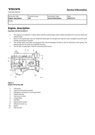
  • 1. Service Information Document Title: Function Group: Information Type: Date: Engine, description 210 Service Information 2014/7/1 0 Profile: Engine, description Cummins LTA 10–C & M11–C     The engine is a 6-cylinder, 4-stroke, direct injected, turbocharged, water cooled assembly with a cast iron block and cylinder head. Gears in the engine gear case are hardened helical type for strength and reduced noise, arranged to provide quiet, smooth transmission of power. The cylinder block and head are designed with internal passages formed as sets for lubrication and cooling. The water pump and oil cooler are integrally mounted. The fan belt is a poly type V-belt for improved performance. Figure 1 Engine fuel pump side 1. 2. 3. 4. 5. 6. 7. 8. 9. 10. 11. Fuel pump Fuel shut–off manual override Refrigerant compressor mounting location Engine data tag Fuel return to tank Coolant filter Fuel filter Engine serial number Oil pressure pick–up Starter Side oil drain
  • 2. Figure 2 Engine exhaust side 1. 2. 3. 4. 5. 6. 7. 8. 9. Provision for coolant heater Heater supply Coolant temperature pick–up Engine vent (coolant) Heater return Make–up line from radiator Coolant inlet Oil drain Provision for oil pan sump heater Engine characteristic curve (EC360) Cummins LTA 10–C Engine characteristics Item Specifications Rated output (Net) 250 PS / 1700 rpm (248 HP / 1700 rpm) Max. torque (Net) 114 kgf·m /1300 rpm (823 lbf·ft / 1300 rpm) Min. fuel consumption 152 g / PS·h Rated fuel consumption 153 g / PS·h
  • 3. Figure 3 Engine, characteristic curve (EC360) A Fuel consumption (g/PS–HR) C Engine speed (RPM) B Torque (kg–m) D Power (PS) NOTE! For detailed information on the engine, consult the separate engine service manual Engine characteristic curve (EC360) Cummins M11–C Engine characteristics Item Specifications Rated output (Net) 250 PS / 1700 rpm (248 HP / 1700 rpm) Max. torque (Net) 120 kgf·m / 1300 rpm (866 lbf·ft / 1300 rpm) Min. fuel consumption 153 g / PS·h Rated fuel consumption 157 g / PS·h
  • 4. Figure 4 Engine, characteristic curve (EC360) A Fuel consumption (g/PS–HR) C Engine speed (RPM) B Torque (kg–m) D Power (PS) NOTE! For detailed information on the engine, consult the separate engine service manual Engine characteristic curve (EC460) Cummins LTA 10–C Engine characteristics Item Specifications Rated output (Net) 300 PS / 2000 rpm (298 HP / 2000 rpm) Max. torque (Net) 135 kgf·m /1500 rpm (975 lbf·ft / 1500 rpm) Min. fuel consumption 152 g / PS·h Rated fuel consumption 156 g / PS·h
  • 5. Figure 5 Engine, characteristic curve (EC460) A Fuel consumption (g/PS–HR) C Engine speed (RPM) B Torque (kg–m) D Power (PS) NOTE! For detailed information on the engine, consult the separate engine service manual Engine characteristic curve(EC460) Cummins M11-C Engine characteristics Item Specifications Rated output (Net) 300 PS / 2000 rpm (298 HP / 2000 rpm) Max. torque (Net) 120 kgf·m / 1500 rpm (866 lbf·ft / 1500 rpm) Min. fuel consumption 150 g / PS·h Rated fuel consumption 160 g / PS·h
  • 6. Figure 6 Engine, characteristic curve (EC460) A Fuel consumption (g/PS–HR) C Engine speed (RPM) B Torque (kg–m) D Power (PS) NOTE! For detailed information on the engine, consult the separate engine service manual
  • 7. Service Information Document Title: Function Group: Information Type: Date: Adjusting engine valve and injectors 214 Service Information 2014/7/1 0 Profile: Adjusting engine valve and injectors Valves and injectors must be correctly adjusted for the engine to operate efficiently. Valve and injector adjustment must be performed using the values listed in this section. The table gives the adjustment limits for fixed timed engines. Adjust the valves and the injectors at each 1500 hours or 1 year maintenance interval. If the valves and injectors have been adjusted during troubleshooting or before the 1500 hours or 1 year scheduled maintenance interval, adjustment is not required at this time. Valve and injector adjustment limits Valve and injector Adjustment Limits “Top stop” Injector Preload : 0.6 ~ 0.7 N·m Intake valve mm 0.35 0.014 Exhaust valve in 0.68 0.027 All overhead valve and injector adjustments must be made when the engine is cold, and stabilized coolant temperature is 60 °C (140 °F) or below. Figure 1 Valve and injector adjustment condition Remove the crankcase breather tube from the crankcase breather outlet. Remove the 16 capscrews, isolators and spacers from the cover. Remove the rocker lever cover and gasket. Figure 2 Remove the rocker lever cover and gasket
  • 8. Each cylinder has three rocker levers :    The long rocker lever (E) is the exhaust lever. The center rocker lever is the injector lever. The short rocker lever (I) is the intake lever. Refer to the figure for valve rocker lever locations. Figure 3 Valve rocker lever locations The crankshaft rotation is clockwise when viewed from the front of the engine. The cylinders are numbered from the front gear cover end of the engine. The engine firing order is 1–5–3–6–2–4 Figure 4 The engine firing order The valves and injectors on the same cylinders are not adjusted at the same index mark on the accessory drive pulley on fixed timed engines. One pair of valves and one injector are adjusted at each pulley index mark before rotating the accessory drive to the next index mark. Two crankshaft revolutions are required to adjust all the valves and injectors. Injector and valve adjustment sequence Injector and valve adjustment sequence Set cylinder Bar engine in direction of rotation Pulley position Injector Valve Start Advance to Advance to Advance to Advance to Advance to A B C A B C 3 6 2 4 1 5 5 3 6 2 4 1 Firing order : 1 – 5 – 3 – 6 – 2 – 4 WARNING Do not pull or pry on the fan to manually rotate the crankshaft. To do so can damage the fan blades. Damaged fan blades can cause premature fan failures which can result in serious personal injury or property damage. The valve set marks are located on the accessory drive pulley. The marks align with a pointer on the gear cover. Use the accessory drive shaft to rotate the crankshaft.
  • 9. Figure 5 Rotation, crankshaft The adjustment can begin on any valve set mark. In the following example the adjustment will begin on the ‘A’ valve set mark with cylinder No. 5 valves closed and cylinder No. 3 injector ready for adjustment. Rotate the accessory drive shaft clockwise until the ‘A’ valve set mark on the accessory drive pulley is aligned with the pointer on the gear cover. Figure 6 Position, valve mark When the ‘A’ mark is aligned with the pointer, the intake and exhaust valves for cylinder No. 5 must be closed. If these conditions are correct, cylinder No. 4 injector and cylinder No. 2 valves are ready to set. Both valves are closed when both rockers are loose, and can be moved from side to side. Figure 7 Position, valve Loosen the injector adjusting screw locknut on cylinder No. 3 Tighten the adjusting screw until all the clearance is removed from the injector train. Tighten the adjusting screw one additional turn to correctly seat the link.
  • 10. Figure 8 Adjustment, injector Loosen the injector adjusting screw until the injector spring retainer washer touches the top stop screw. Figure 9 Adjustment, injector CAUTION An over-tightened setting on the injector adjusting screw will produce increased stress on the injector train and the camshaft injector lobe which can result in engine damage. Use torque wrench to tighten the adjusting screw. Tightening torque : 0.6 ~ 0.7 N·m (5 ~6 lb·in) Figure 10 Tightening torque, adjusting screw Hold the adjusting screw in this position. The adjusting screw must not turn when the locknut is tightened. Tightening torque :   Without torque wrench adapter : 61 N·m (45 lbf·ft) With torque wrench adapter (1) : (Part no. ST–669) 47 N·m (35 lbf·ft)
  • 11. Figure 11 Tightening torque, adjusting screw Adjust the valves on the appropriate cylinder according to the sequence chart before rotating the accessory drive to the next valve set mark. Injector and valve adjustment sequence Injector and valve adjustment sequence Set cylinder Bar engine in direction of rotation Pulley position Injector Valve Start Advance to Advance to Advance to Advance to Advance to A B C A B C 3 6 2 4 1 5 5 3 6 2 4 1 Firing order : 1 – 5 – 3 – 6 – 2 – 4 Select a feeler gauge for the correct valve lash specifications. Valve lash specifications Valve lash specifications Intake Exhaust 0.36 mm (0.014 in) 0.69 mm (0.027 in) Insert the feeler gauge between the top of the cross-head and the rocker lever pad. Figure 12 Checking, clearance Two different methods for establishing valve lash clearance are described below. Either method can be used, however, the torque wrench method has proven to be the most consistent. It eliminated the need to feel the drag on the feeler gauge.  Torque wrench method :
  • 12. Use the inch pound torque wrench, (Part No. 3376592) (Normally used to set preload on top stop injectors) and tighten the adjusting screw. Tightening torque : 0.7 N·m (6 lb·in)  Touch method : Tighten the adjusting screw until a light drag is felt on the feeler gauge. Figure 13 Adjusting, valve clearance Hold the adjusting screw in this position. The adjusting screw must not turn when the locknut is tightened. Tighten the locknut. Tightening torque :   Without torque wrench adapter : 61 N·m (45 lbf·ft) With torque wrench adapter (1) : (Part no. St–669) 47 N·m (35 lbf·ft) Figure 14 Tightening torque, locknut After tightening the locknut to the correct torque value, check to make sure the feeler gauge will slide backward and forward between the cross– 4head and the rocker lever with only a slight drag. Figure 15 Checking, locknut torque If using the touch method, attempt to insert a feeler gauge that is 0.03 mm (0.001 in) thick between the cross–head and the
  • 13. rocker lever pad. The valve lash is not correct when a thicker feeler gauge will fit. Figure 16 Checking, valve lash Adjust the jacobs engine brake, if applicable, after adjusting the valves before rotating the accessory drive pulley to the next index mark. Refer to jacobs engine brake–adjustment following this procedure. After adjusting the valves, rotate the accessory drive and align the next valve set mark on the accessory drive pulley with the pointer on the gear cover. Figure 17 Marking, drive pulley with the pointer on the gear cover Adjust the appropriate injector and valves following the injector and valve adjustment sequence chart. Repeat the process to adjust all injectors and valves. After adjusting all the valves and injectors, check the torque on the adjusting screw locknuts to make sure none were overlooked. Injector and valve adjustment sequence Injector and valve adjustment sequence Set cylinder Bar engine in direction of rotation Pulley position Injector Valve Start Advance to Advance to Advance to Advance to Advance to A B C A B C 3 6 2 4 1 5 5 3 6 2 4 1 Firing order : 1 – 5 – 3 – 6 – 2 – 4 If the valve cover gasket was not damaged, it can be used again. If the gasket was damaged, it must be discarded and a new one used. Install the gasket on the cover.
  • 14. Figure 18 Install the gasket on the cover Install the cover on the rocker lever housing. Install the 16 isolators, spacers and capscrews in the cover. Figure 19 Install the cover on the rocker lever housing Tighten the capscrews in the sequence shown. Torque value : 15 N·m (130 lb·in) Figure 20 Tighten the capscrews Install the hose on the crankcase breather. Figure 21 Install, breather
  • 15. Service Information Document Title: Function Group: Information Type: Date: Engine mounting 218 Service Information 2014/7/1 0 Profile: Engine mounting Figure 1 Engine mounting, side view CAUTION Check the color markings for cushion installation. Front (fan side) – Blue and white Rear (flywheel side) – Green Figure 2 Cushion Tightening torque, unit : kgf·m (lbf·ft) No. Mounting position Tightening torque Front (A) 52 ± 5 (375 ± 36) 1 Engine mounting bracket Rear (B) 18 ~ 20 (133 ~ 144) Front (A) 70 ± 7 (505 ± 50) 2 Engine mounting cushion Rear (B) 90 ± 9 (650 ± 65)
  • 16. Service Information Document Title: Function Group: Information Type: Date: Lubrication system 220 Service Information 2014/7/1 0 Profile: Lubrication system Engine lubricating oil is supplied to the contact faces of rotating components such as air compressor, camshaft, piston, intake/exhaust valve, rocker arm and timing gear by means of forced lubrication from the oil pump. Lubricating oil flow diagram Figure 1 Lubricating oil flow diagram 1. 2. 3. 4. 5. 6. 7. 8. 9. 10. 11. 12. Oil pump Pressure regulator valve Oil return to pan High pressure relief valve Oil return to pan Cooled oil bypass valve Oil cooler Bypass filtered oil return Combination oil filter Filter bypass valve Accessory drive/air compressor Idler gears
  • 17. Service Information Document Title: Function Group: Information Type: Date: Fuel injection system 230 Service Information 2014/7/1 0 Profile: Fuel injection system Highly pressurized fuel compressed by the fuel PT pump is direct injected through the injection nozzle into the combustion chamber. Remaining fuel after injection is returned to tank automatically. A water separator installed to protect the fuel system components provides a means to drain off the water and contaminants collected from the system. Figure 1 Fuel injection system 1. 2. 3. 4. 5. 6. 7. Fuel inlet supply Fuel filter Fuel PT pump Fuel to injectors Injector Fuel drain return Gear pump cooling return
  • 18. Service Information Document Title: Function Group: Information Type: Date: Fuel tank, description 2341 Service Information 2014/7/1 0 Profile: Fuel tank, description Figure 1 Fuel tank 1 Tank 6 O–ring 11 Spring washer 2 Cap 7 Capscrew 12 Capscrew 3 Screen 8 Plain washer 13 Level gauge 4 Drain cock 9 Spring washer 5 Plug 10 Shim  When mounting the tank, adjust the height by use of shim (10). Tightening torque :    Bolt (7) : 52.2 ± 5.2 kgf·m (377 ± 38 lbf·ft) Drain cock : 1.6 ~ 1.9 kgf·m (11.6 ~13.7 lbf·ft) Bolt (13) : 2.0 ± 0.2 kgf·m ( 14 ± 1.4 lbf·ft )
  • 19. Suggest: If the above button click is invalid. Please download this document first, and then click the above link to download the complete manual. Thank you so much for reading
  • 20. Service Information Document Title: Function Group: Information Type: Date: Fuel filling pump, description 2344 Service Information 2014/7/1 0 Profile: Fuel filling pump, description   The pump outlet is plumbed directly to the fuel tank to reduce the risk of introducing contamination. The master switch must be in the ON position to operate the fuel filling pump. CAUTION The filter at the end of fuel filling pump inlet hose is a strainer, and will not filter impurities from the fuel. When filling use CLEAN fuel only! CAUTION Do not operate the fuel filling pump without fuel or for extended periods of time. CAUTION Drain the fuel from the suction hose before putting it in the storage compartment. CAUTION In case of the pump has been disassembled, assemble the pump so the that the sharp portion of the vane faces the counterclockwise direction. Figure 1 Structure, fuel filling pump (35 liter) 1. X : Section X - X