
Recommended
Recommended
More Related Content
What's hot
What's hot (6)
Similar to Hitachi ex1200 5 excavator service repair manual
Similar to Hitachi ex1200 5 excavator service repair manual (11)
More from fhhsjdkmem
More from fhhsjdkmem (20)
Recently uploaded
Recently uploaded (20)
Hitachi ex1200 5 excavator service repair manual
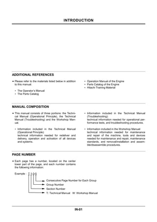
- 1. INTRODUCTION IN-01 ADDITIONAL REFERENCES Please refer to the materials listed below in addition to this manual. The Operator’s Manual The Parts Catalog Operation Manual of the Engine Parts Catalog of the Engine Hitachi Training Material MANUAL COMPOSITION This manual consists of three portions: the Techni- cal Manual (Operational Principle), the Technical Manual (Troubleshooting) and the Workshop Man- ual. Information included in the Technical Manual (Operational Principle): technical information needed for redeliver and delivery, operation and activation of all devices and systems. Information included in the Technical Manual (Troubleshooting): technical information needed for operational per- formance tests, and troubleshooting procedures. Information included in the Workshop Manual: technical information needed for maintenance and repair of the machine, tools and devices needed for maintenance and repair, maintenance standards, and removal/installation and assem- ble/disassemble procedures. PAGE NUMBER Each page has a number, located on the center lower part of the page, and each number contains the following information: Example : T 1-3-5 Consecutive Page Number for Each Group Group Number Section Number T: Technical Manual W: Workshop Manual
- 2. SECTION AND GROUP CONTENTS WORKSHOP MANUAL SECTION 1 GENERAL INFORMATION Group 1 Precautions for disassembling and Assembling Group 2 Tightening Torque SECTION 2 UPPERSTRUCTURE Group 1 Cab Group 2 Counterweight Group 3 Main Frame Group 4 Pump Device Group 5 Control Valve Group 6 Swing Device Group 7 Pilot Valve Group 8 Pilot Shut-Off Valve Group 9 Shockless Valve SECTION 3 UNDERCARRIAGE Group 1 Swing Bearing Group 2 Travel Device Group 3 Center Joint Group 4 Track Adjuster Group 5 Front Idler Group 6 Upper and Lower Roller Group 7 Track SECTION 4 FRONT ATTACHMENT Group 1 Front Attachment Group 2 Cylinder SECTION 5 ENGINE TECHNICAL MANUAL (Operational Principle) SECTION 1 GENERAL Group 1 Specification Group 2 Component Layout SECTION 2 SYSTEM Group 1 Control System Group 2 Hydraulic System Group 3 Electrical System SECTION 3 COMPONENT OPERATION Group 1 Pump Device Group 2 Swing Device Group 3 Control Valve Group 4 Pilot Valve Group 5 Travel Device Group 6 Others(Upperstructure) Group 7 Others(Undercarriage) TECHNICAL MANUAL (Troubleshooting) SECTION 4 OPERATIONAL PER- FORMANCE TEST Group 1 Introduction Group 2 Engine Test Group 3 Excavator Test Group 4 Hydraulic Component Test Group 5 Standard SECTION 5 TROUBLESHOOTING Group 1 Diagnosing Procedure Group 2 Component Layout Group 3 Troubleshooting A Group 4 Troubleshooting B Group 5 Troubleshooting C Group 6 Electrical System Inspection
- 3. 183W-1-1 SECTION 1 GENERAL INFORMATION CONTENTS Group 1 Precautions for Disassembling and Assembling Precautions for Disassembling and Assembling........................................... W1-1-1 Maintenance Standard Terminology........ W1-1-7 Group 2 Tightening Torque Tightening Torque Specification.............. W1-2-1 Torque Chart .......................................... W1-2-3 Piping Joint ............................................ W1-2-6 Periodic Replacement of Parts ............. W1-2-10
- 4. GENERAL / Precautions for Disassembling and Assembling W1-1-1 PRECAUTIONS FOR DISASSEMBLING AND ASSEMBLING Precautions for Disassembling and Assembling • Clean the Machine Thoroughly wash the machine before bringing it into the shop. Bringing a dirty machine into the shop may cause machine components to be contaminated during disassembling/assembling, resulting in damage to machine components, as well as decreased efficiency in service work. • Inspect the Machine Be sure to thoroughly understand all disassem- bling/assembling procedures beforehand, to help avoid incorrect disassembling of components as well as personal injury. Check and record the items listed below to prevent problems from occurring in the future. • The machine model, machine serial number, and hour meter reading. • Reason for disassembly (symptoms, failed parts, and causes). • Clogging of filters and oil, water or air leaks, if any. • Capacities and condition of lubricants. • Loose or damaged parts. • Prepare and Clean Tools and Disassembly Area Prepare the necessary tools to be used and the area for disassembling work. • Precautions for Disassembling • To prevent dirt from entering, cap or plug the removed pipes. • Before disassembling, clean the exterior of the components and place on a work bench. • Before disassembling, drain gear oil from the reduction gear. • Be sure to provide appropriate containers for draining fluids. • Use matching marks for easier reassembling. • Be sure to use the specified special tools, when instructed. • If a part or component cannot be removed after removing its securing nuts and bolts, do not attempt to remove it forcibly. Find the cause(s), then take the appropriate measures to remove it. • Orderly arrange disassembled parts. Mark and tag them as necessary. • Store common parts, such as bolts and nuts with reference to where they are to be used and in a manner that will prevent loss. • Inspect the contact or sliding surfaces of disassembled parts for abnormal wear, sticking, or other damage. • Measure and record the degree of wear and clearances.
- 5. GENERAL / Precautions for Disassembling and Assembling W1-1-2 • Precautions for Assembling • Be sure to clean all parts and inspect them for any damage. If any damage is found, repair or replace part. • Dirt or debris on the contact or sliding surfaces may shorten the service life of the machine. Take care not to contaminate any contact or sliding surfaces. • Be sure to replace O-rings, backup rings, and oil seals with new ones once they are disassembled. Apply a film of grease before installing. • Be sure that liquid-gasket-applied surfaces are clean and dry. • If an anti-corrosive agent has been used on a new part, be sure to thoroughly clean the part to remove the agent. • Utilize matching marks when assembling. • Be sure to use the designated tools to assemble bearings, bushings and oil seals. • Keep a record of the number of tools used for disassembly/assembly. After assembling is complete, count the number of tools, so as to make sure that no forgotten tools remain in the assembled machine. Bleeding Air from Hydraulic System When hydraulic oil is drained, the suction filter or the suction lines are replaced, or the removal and instal- lation of the pump, swing motor, travel motor or cylin- der is done, bleed air from the hydraulic system in the following procedures: IMPORTANT: If the engine is started with air trapped in the hydraulic pump hous- ing, damage to the pump may result. If the hydraulic motor is operated with air trapped in the hydraulic mo- tor housing, damage to the motor may result. If the cylinder is operated with air trapped in the cylinder tube, damage to the cylinder may result. Be sure to bleed air before starting the engine. • Bleeding Air from Hydraulic Pump • Remove the air bleeding plug from the top of the pump and fill the pump housing with hydraulic oil. • After the pump housing is filled with hydraulic oil, temporarily tighten the plug. Then, start the en- gine and run at slow idle speed. • Slightly loosen the plug to bleed air from the pump housing until hydraulic oil oozes out. • After bleeding all the air, securely tighten the plug. • Bleeding Air from Travel Motor / Swing Motor • With the drain plug / hose on travel motor / swing motor removed, fill the motor case with hydraulic oil.
- 6. GENERAL / Precautions for Disassembling and Assembling W1-1-3 • Bleeding Air from Hydraulic Circuit • After refilling hydraulic oil, start the engine. While operating each cylinder, swing motor and travel motor evenly, operate the machine under light loads for 10 to 15 minutes. Slowly start each op- eration (never fully stroke the cylinders during ini- tial operation stage). As the pilot oil circuit has an air bleed device, air trapped in the pilot oil circuit will be bled while performing the above operation for approx. 5 minutes. • Reposition the front attachment to check hydraulic oil level. • Stop the engine. Recheck hydraulic oil level. Re- plenish oil as necessary. W183-04-02-003 W183-04-02-002
- 7. GENERAL / Precautions for Disassembling and Assembling W1-1-4 Floating Seal Precautions 1. In general, replace the floating seal with a new one after disassembling. If the floating seal is to be reused, follow these procedures: (1) Keep seal rings together as a matched set with seal ring faces together. Insert a piece of cardboard to protect surfaces. (2) Check the slide surface on seal ring (A) for scuffing, scoring, corrosion, deformation or uneven wear. (3) Check O-ring (B) for tears, breaks, deformation or hardening. 2. If incorrectly assembled, oil leakage or damage will occur. Be sure to do the following, to prevent trouble. (1) Clean the floating seal and seal mounting bores with cleaning solvent. Use a wire brush to remove mud, rust or dirt. After cleaning, thoroughly dry parts with compressed air. (2) Clean the floating seal and seal mounting bores. Check the bore surface for scuffing or scoring by touching the surface with touch. (3) Check that the O-ring is not twisted, and that it is installed correctly on the seal ring. (4) After installing the floating seal, check that seal ring surface (A) is parallel with seal mating face (C) by measuring the distances (A) and (C) at point (a) and (b), as illustrated. If these distances differ, correct the O-ring seating. W105-03-05-019 W105-03-05-020 W110-03-05-004 a b b b a a a=b C A B Incorrect Correct Incorrect Correct A B
- 8. GENERAL / Precautions for Disassembling and Assembling W1-1-5 Precautions for Using Nylon Sling 1. Follow the precautions below to use nylon slings safely. • Attach protectors (soft material) on the corners of the load so that the nylon sling does not directly contact the corners. This will prevent the nylon sling from being damaged and the lifted load from slipping. • Lower the temperature of the lifted load to lower than 100 °C (212 °F). If unavoidably lifting a load with a temperature of 100 °C (212 °F) or more, reduce the load weight. • Do not lift acid or alkali chemicals. • Take care not to allow the sling to become wet. The load may slip. • When required to use more than one sling, use slings with the same width and length to keep the lifted load balanced. • When lifting a load using an eyehole, be sure to eliminate any gaps between the sling and load. (Refer to the right illustration.) Reduce the load weight so that it is less than 80 % of the sling breaking force. • Avoid using twisted, bound, connected, or hitched slings. • Do not place any object on twisted or bent slings. (Refer to the right illustration.) • When removing the slings from under the load, take care not to damage the nylon slings. Avoid contact with protrusions. • Avoid dragging slings on the ground, throwing slings or pushing slings with a metal object. • When using with other types of slings (wire rope) or accessories (shackle), protect the joint so that the nylon sling is not damaged. • Store the nylon slings indoors so they won’t dete- riorate with heat, sun light, or chemicals. W102-04-02-016 W105-04-01-008 W162-01-01-009 Correct Eyehole Lifting Method Incorrect Eyehole Lifting Method Bent Sling
- 9. GENERAL / Precautions for Disassembling and Assembling W1-1-6 CAUTION: If a load is lifted with a damaged nylon sling, serious personal injury may re- sult. Be sure to visually check the nylon sling for any damage before using. 2. Before using a nylon sling, visually check the ny- lon sling for any damage corresponding to exam- ples shown to the right. If any damage is found, cut and discard the sling. Even if no damage is found, do not use slings older than 7-years. Damaged Appearance W162-01-01-002 W162-01-01-003 W162-01-01-004 W162-01-01-005 W162-01-01-006 W162-01-01-007 W162-01-01-008 Broken Sewing Thread Scuffing Broken Sewing Thread Fuzz Broken Sewing Thread Separation of Belt Broken Sewing Thread Scuffing Scoring Broken Warp Fuzz
- 10. GENERAL / Precautions for Disassembling and Assembling W1-1-7 MAINTENANCE STANDARD TERMINOL- OGY “Standard” 1. Dimension for parts on a new machine. 2. Dimension of new components or assemblies adjusted to specification. “Allowable Limit” 1. Normal machine performance cannot be accom- plished after exceeding this limit. 2. Repair or adjustment is impossible after exceed- ing this limit. 3. Therefore, in consideration of operation efficiency and maintenance expense, proper maintenance shall be carried out before reaching the “Allowable Limit”.
- 11. GENERAL / Tightening W1-2-1 TIGHTENING TORQUE SPECIFICATIONS Torque Descriptions Bolt Dia. (mm) Q’ty Wrench Size mm N m (kgf m) (lbf ft) Engine cushion rubber mounting bolt(Fan side) (Pump side) 22 33 2 2 32 50 740 2550 (75) (260) (540) (1880) Engine bracket mounting bolt 27 12 41 1030 (105) (760) Radiator mounting bolt 27 4 30 1030 (105) (760) Hydraulic oil tank mounting bolt 20 8 30 540 (55) (400) Fuel tank mounting bolt 20 8 41 540 (55) (400) ORS fittings for hydraulic hoses and piping 1-7/16- 12UNF 1-11/16- 12UNF 4 4 41 50 205 340 (21) (35) (152) (251) Pump mission mounting bolt 1/2-13UNF 16 19 118 (12) (87) Pump device mounting bolt(Hexagon wrench) 20 12 17 390 (40) (290) Pump mounting bolt(Hexagon wrench) 16 4 14 205 (21) (152) Gear pump mounting bolt 27 2 22 137 (14) (102) Control valve mounting bolt 20 8 30 390 (40) (290) Swing control valve mounting bolt 16 3 17 49 (5) (36) Swing device mounting bolt 27 32 41 1370 (140) (1010) Swing motor mounting bolt 12 24 19 88 (9) (65) Battery mounting nut 12 2 19 34 (3.5) (26) Cab mounting bolt 16 8 24 265 (27) (195) Cab bed mounting bolt 16 58 24 205 (21) (152) Swing bearing mounting bolt(Upperstructure) (Undercarriage) 36 36 52 50 55 55 2750 2750 (280) (280) (2030) (2030) Travel device mounting bolt Travel motor mounting bolt Sprocket mounting bolt 27 18 27 52 8 60 41 27 41 1370 295 1370 (140) (30) (140) (1010) (215) (1010) Upper roller mounting bolt 20 24 30 540 (55) (400) Lower roller mounting bolt 27 64 41 1370 (140) (1010) Shoe mounting bolt 30 416 46 2840 (290) (2100) Track guard mounting bolt 27 28 41 1370 (140) (1010) Side frame mounting bolt 42 52 65 3920 (400) (2900) Counterweight mounting bolt 45 6 63 3920 (400) (2900) Oil cooler mounting bolt 24 4 36 930 (95) (690) Front pin-retaining(Backhoe) Stopper bolt A Stopper bolt B 20 20 12 12 30 30 390 390 (40) (40) (290) (290) Front pin-retaining(Loading shovel) Stopper bolt A Stopper bolt B Stopper bolt C Stopper bolt D 20 20 16 12 14 4 18 6 30 17 24 19 390 540 265 88 (40) (55) (27) (9) (290) (400) (195) (65) Side cutter mounting bolt 33 12 50 2550 (260) (1880)
- 12. Thank you very much for your reading. Please Click Here. Then Get COMPLETE MANUAL. NO WAITING NOTE: If there is no response to click on the link above, please download the PDF document first and then click on it.
- 13. GENERAL / Tightening W1-2-2 NOTE 1. Apply lubricant (e.g. white zinc B dissolved into spindle oil) to bolts and nuts to reduce friction coefficient of them. 2. Make sure bolt and nut threads are clean before installing. 3. Apply LOCTITE to threads before installilng and tightening swing bearing mounting bolts and lower roller mounting bolts.
- 14. GENERAL / Tightening W1-2-3 TORQUE CHART CAUTION: Use tools appropriate for the work to be done. Makeshift tools and proce- dures can create safety hazards. For loosen- ing and tightening nuts and bolts, use correct size tools. Otherwise, tightening tools may slip, potentially causing personal injury. Bolt Types Tighten nuts or bolts correctly to torque specifications. Four different types and grades of bolt are employed. Make sure to employ correct bolts and tighten them correctly when assembling the machine or compo- nents. SA-040 W162-01-01-001 Specified Tightening Torque Chart T Bolt H Bolt, Socket bolt M Bolt Bolt Dia. Wrench Size Hexagon Wrench Size N m (kgf m) (lbf ft) N m (kgf m) (lbf ft) N m (kgf m) (lbf ft) M 8 13 6 29.5 (3) (22) 19.5 (2) (14.5) 9.8 (1) (7.2) M 10 17 8 64 (6.5) (47) 49 (5) (36) 19.5 (2) (14.5) M 12 19 10 108 (11) (80) 88 (9) (65) 34 (3.5) (25.5) M 14 22 12 175 (18) (130) 137 (14) (101) 54 (5.5) (40) M 16 24 14 265 (27) (195) 205 (21) (152) 78 (8) (58) M 18 27 14 390 (40) (290) 295 (30) (220) 118 (12) (87) M 20 30 17 540 (55) (400) 390 (40) (290) 167 (17) (123) M 22 32 17 740 (75) (540) 540 (55) (400) 215 (22) (159) M 24 36 19 930 (95) (690) 690 (70) (505) 275 (28) (205) M 27 41 19 1370 (140) (1010) 1030 (105) (760) 390 (40) (290) M 30 46 22 1910 (195) (1410) 1420 (145) (1050) 540 (55) (400) M 33 50 24 2550 (260) (1880) 1910 (195) (1410) 740 (75) (540) M 36 55 27 3140 (320) (2310) 2400 (245) (1770) 930 (95) (690) Socket Bolt Hexagon M Bolt Hexagon H Bolt Hexagon T Bolt