
Recommended
Recommended
More Related Content
Similar to 2003 Nissan Altima Service Repair Manual.pdf
Similar to 2003 Nissan Altima Service Repair Manual.pdf (20)
More from f7seujdkdmdm7y
More from f7seujdkdmdm7y (13)
Recently uploaded
Recently uploaded (20)
2003 Nissan Altima Service Repair Manual.pdf
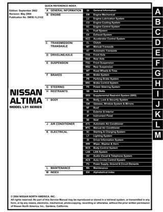
- 1. -1 QUICK REFERENCE INDEX A GENERAL INFORMATION GI General Information B ENGINE EM Engine Mechanical LU Engine Lubrication System CO Engine Cooling System EC Engine Control System FL Fuel System EX Exhaust System ACC Accelerator Control System C TRANSMISSION/ TRANSAXLE CL Clutch MT Manual Transaxle AT Automatic Transaxle D DRIVELINE/AXLE FAX Front Axle RAX Rear Axle E SUSPENSION FSU Front Suspension RSU Rear Suspension WT Road Wheels & Tires F BRAKES BR Brake System PB Parking Brake System BRC Brake Control System G STEERING PS Power Steering System H RESTRAINTS SB Seat Belts SRS Supplemental Restraint System (SRS) I BODY BL Body, Lock & Security System GW Glasses, Window System & Mirrors RF Roof EI Exterior & Interior IP Instrument Panel SE Seat J AIR CONDITIONER ATC Automatic Air Conditioner MTC Manual Air Conditioner K ELECTRICAL SC Starting & Charging System LT Lighting System DI Driver Information System WW Wiper, Washer & Horn BCS Body Control System LAN LAN System AV Audio Visual & Telephone System ACS Auto Cruise Control System PG Power Supply, Ground & Circuit Elements L MAINTENANCE MA Maintenance M INDEX IDX Alphabetical Index Edition: September 2002 Revision: May 2004 Publication No. SM3E-1L31U2 B D © 2004 NISSAN NORTH AMERICA, INC. All rights reserved. No part of this Service Manual may be reproduced or stored in a retrieval system, or transmitted in any form, or by any means, electronic, mechanical, photo-copying, recording or otherwise, without the prior written permission of Nissan North America, Inc., Gardena, California. A C E F G H I J K L M
- 2. -2 FOREWORD This manual contains maintenance and repair procedures for the 2003 NISSAN ALTIMA. In order to assure your safety and the efficient functioning of the vehicle, this manual should be read thoroughly. It is especially important that the PRECAUTIONS in the GI section be completely understood before starting any repair task. All information in this manual is based on the latest product information at the time of publication. The right is reserved to make changes in specifi- cations and methods at any time without notice. IMPORTANT SAFETY NOTICE The proper performance of service is essential for both the safety of the technician and the efficient functioning of the vehicle. The service methods in this Service Manual are described in such a manner that the service may be performed safely and accurately. Service varies with the procedures used, the skills of the technician and the tools and parts available. Accordingly, anyone using service procedures, tools or parts which are not specifically recommended by NISSAN must first be completely satisfied that neither personal safety nor the vehicle’s safety will be jeopardized by the service method selected.
- 3. QUICK REFERENCE CHART: ALTIMA (EQUIPPED WITH 2.5L, QR ENGINE) 2003 QUICK REFERENCE CHART: ALTIMA (EQUIPPED WITH 2.5L, QR ENGINE) PFP:00000 Engine Tune-Up Data ELS000ME Drive Belt Deflection and Tension Spark Plugs (Double Platinum Tipped) Front Wheel Alignment (Unladen*1) ELS000MF Cylinder arrangement In-line 4 Displacement cm3 (cu in) 2,488 (151.82) Bore and stroke mm (in) 89.0 x 100 (3.50 - 3.94) Valve arrangement DOHC Firing order 1-3-4-2 Number of piston rings Compression 2 Oil 1 Compression ratio 9.5:1 Compression pressure kPa (kg/cm2, psi) / 250 rpm Standard 1,250 (12.8, 182) Minimum 1,060 (10.8, 154) Differential limit between cylinders 98 (1.0, 14) Idle speed A/T (in neutral) rpm 700 ± 50 Ignition timing (BTDC at idle speed) 15° ± 5° CO% at idle 0.3 – 9.5% and engine runs smoothly Radiator cap relief pressure kPa (kg/cm2, psi) Standard 79 – 98 (0.8 – 1.0, 11 – 14) Limit 59 (0.6, 9) Cooling system leakage testing pressure kPa (kg/cm2 , psi) 157 (1.6, 23) Tension of drive belts Auto adjustment by auto-tensioner Type Standard PLFR5A-11 Hot PLFR4A-11 Cold PLFR6A-11 Plug gap Nominal: 1.1 mm (0.043 in) Tire size 205/65R16 215/55R17 Camber Degree minute (Decimal degree) Minimum −1°00′ (−1.00°) Nominal −0°15′ (−0.25°) Maximum 0°30′ (0.50°) Left and right difference 45′ (0.75°) or less SFA234AC
- 4. 2003 QUICK REFERENCE CHART: ALTIMA (EQUIPPED WITH 2.5L, QR ENGINE) *1: Fuel, radiator coolant and engine oil full. Spare tire, jack, hand tools and mats in designated positions. *2: On power steering models, wheel turning force (at circumference of steering wheel) of 98 to 147 N (10 to 15 kg, 22 to 33 lb) with engine idle. Rear Wheel Alignment (Unladen*) ELS000MG *: Fuel, radiator coolant and engine oil full. Spare tire, jack, hand tools and mats in designated positions. Caster Degree minute (Decimal degree) Minimum 2°05′ (2.08°) Nominal 2°50′ (2.83°) Maximum 3°35′ (3.58°) Left and right difference 45′ (0.75°) or less Kingpin inclination Degree minute (Decimal degree) Minimum 13°50′ (13.83°) Nominal 14°35′ (14.58°) Maximum 15°20′ (15.33°) Total toe-in Distance (A − B) mm (in) Minimum −0.5 (−0.02) Nominal 0.5 (0.02) Maximum 1.5 (0.06) Angle (left plus right) Degree minute (Decimal degree) Minimum −4′ (−0.07°) Nominal 2′ (0.03°) Maximum 8′ (0.13°) Wheel turning angle Full turn*2 Inside Degree minute (Decimal degree) Minimum 34°30′ (34.5°) 32°00′ (32.0°) Nominal 38°00′ (38.0°) 35°30′ (35.5°) Maximum 39°00′ (39.0°) 36°30′ (36.5°) Outside Degree minute (Decimal degree) Nominal 30°30′ (30.5°) 29°00′ (29.0°) Camber Degree minute (Decimal degree) Minimum −0°04′ (−0.07°) Nominal −0°34′ (−0.57°) Maximum 0°64′ (-1.07°) Total toe-in Distance (A − B) mm (in) Minimum 2.4 (0.09) Nominal 3.9 (0.15) Maximum 5.4 (0.21) Angle (left plus right) Degree minute (Decimal degree) Minimum 6′ (0.1°) Nominal 10′ (0.167°) Maximum 14′ (0.233°) SFA234AC
- 5. QUICK REFERENCE CHART: ALTIMA (EQUIPPED WITH 2.5L, QR ENGINE) 2003 Brake ELS000MH Unit: mm (in) Disc Brake - Repair Limits Unit: mm (in) Brake Pedal Unit: mm (in) Front brake Brake model CLZ25VD disc brake Cylinder bore diameter 57.2 (2.252) Pad Length × width × thickness 125.6 × 46 × 11 (4.94 × 1.81 × 0.43) Rotor outer diameter × thickness 296 × 26 (11.65 × 1.02) Rear brake Brake model AD9V disc brake Cylinder bore diameter 34.9 (1.3740) Pad Length × width × thickness 89.1 × 39.5 × 10 (3.508 × 1.555 × 0.31) Rotor outer diameter × thickness 292 × 9 (11.50 × 0.35) Master cylinder Cylinder bore diameter 23.81 (15/16) Control valve Screw in type 30 × 0.4 (1.18 × 0.02) Brake booster Booster model M215T Diaphragm diameter Primary 230 (9.06) Secondary 205 (8.07) Recommended brake fluid Genuine NISSAN Super Heavy Duty Brake Fluid or equivalent, DOT 3 (US FMVSS No. 116) Brake model CLZ25VD (Front) AD9V (Rear) Pad wear limit Minimum thickness 2.0 (0.079) 1.5 (0.059) Rotor repair limit Maximum runout 0.07 (0.0028) 0.07 (0.0028) Minimum thickness 22.0 (0.866) 8.0 (0.31) Free height “H”* M/T 164.1 - 174.1 (6.46 - 6.85) A/T 173.1 - 183.1 (6.81 - 7.21) Clearance “C” between pedal stopper and threaded end of stop lamp switch or ASCD switch 0.74 - 1.96 (0.0291 - 0.0772) WFIA0022E
- 6. 2003 QUICK REFERENCE CHART: ALTIMA (EQUIPPED WITH 2.5L, QR ENGINE) *: Measured from surface of dash reinforcement panel to surface of pedal pad Refill Capacities ELS000MI Engine Coolant Capacity (Approximate) Unit: (US qt, Imp qt) Engine Oil Capacity (Approximate) Unit: (US qt, Imp qt) Miscellaneous Capacity (Approximate) Drain and refill (without reservoir) 6.9 (7 1/4, 6 1/8) Reservoir tank (at MAX level) 0.7 (3/4, 5/8) Drain and refill With oil filter change 4.2 (4 1/2, 3 3/4) Without oil filter change 4.0 (4 1/4, 3 1/2) Dry engine (engine overhaul) 4.6 (4 7/8, 4) System description Metric measurement US measurement Imp measure Fuel tank 75.5 20 gal 16 5/8 gal Power steering system 1.0 2 1/8 pt 1 3/4 pt Transaxle M/T (RS5F51A) 2.3 2 3/8 qt 2 qt A/T (RE4F04B) 9.2 9 3/4 qt 8 1/8 qt Air conditioning system Refrigerant 0.475 - 0.525 kg 1.045 - 1.155 lb 1.045 - 1.155 lb Compressor oil 150 m 5.01 fl oz 5.03 fl oz
- 7. QUICK REFERENCE CHART: ALTIMA (EQUIPPED WITH 3.5L, VQ ENGINE) 2003 QUICK REFERENCE CHART: ALTIMA (EQUIPPED WITH 3.5L, VQ ENGINE) PFP:00027 Engine Tune-Up Data ELS000MJ *1: Under the following conditions: ● Air conditioner switch: OFF ● Electric load: OFF (Lights, heater fan & rear window defogger) ● Steering wheel: Kept in straight-ahead position Cylinder arrangement V-6 Displacement cm3 (cu in) 3,498 (213.45) Bore and stroke mm (in) 95.5 x 81.4 (3.76 - 3.205) Valve arrangement DOHC Firing order 1-2-3-4-5-6 Number of piston rings Compression 2 Oil 1 Number of main bearings 4 Compression ratio 10.0:1 Compression pressure kPa (kg/cm2, psi) / 250 rpm Standard 1,275 (13.0, 185) Minimum 981 (10.0, 142) Differential limit between cylinders 98 (1.0, 14) Idle speed rpm No-load*1 (in “P” or N” position) 700 ± 50 Ignition timing (BTDC at idle speed) 15° ± 5° CO% at idle 0.7 – 9.9% and engine runs smoothly Radiator cap relief pressure kPa (kg/cm2 , psi) Standard 79 – 98 (0.8 – 1.0, 11 – 14) Limit 59 (0.6, 9) Cooling system leakage testing pressure kPa (kg/cm2 , psi) 157 (1.6, 23)
- 8. 2003 QUICK REFERENCE CHART: ALTIMA (EQUIPPED WITH 3.5L, VQ ENGINE) Drive Belt Deflection and Tension Spark Plugs (Double Platinum Tipped) Front Wheel Alignment (Unladen*1) ELS000MK Deflection adjustment Unit: mm (in) Tension adjustment Unit: N (kg, lb) Used belt New belt Used belt New belt Limit After adjustment Limit After adjustment Alternator, Air conditioner compressor 7.0 (0.28) 4.2 - 4.6 (0.17 - 0.18) 3.7 - 4.1 (0.15 - 0.16) 294 (30, 66) 730 - 818 (74.5 - 83.5, 164 - 184) 838 - 926 (85.5 - 94.5, 188 - 208) Power steering oil pump 11.0 (0.43) 7.3 - 8.0 (0.29 - 0.32) 6.5 - 7.2 (0.26 - 0.28) 196 (20, 44) 495 - 583 (50.5 - 59.5, 111.3 - 131.1) 603 - 691 (61.5 - 70.5, 135.6 - 155.4) Type Standard PLFR5A-11 Hot PLFR4A-11 Cold PLFR6A-11 Plug gap Nominal: 1.1 mm (0.043 in) Tire size 205/65R16 215/55R17 Camber Degree minute (Decimal degree) Minimum −1°00′ (−1.00°) Nominal −0°15′ (−0.25°) Maximum 0°30′ (0.50°) Left and right difference 45′ (0.75°) or less Caster Degree minute (Decimal degree) Minimum 2°05′ (2.08°) Nominal 2°50′ (2.83°) Maximum 3°35′ (3.58°) Left and right difference 45′ (0.75°) or less Kingpin inclination Degree minute (Decimal degree) Minimum 13°50′ (13.83°) Nominal 14°35′ (14.58°) Maximum 15°20′ (15.33°) Total toe-in Distance (A − B) mm (in) Minimum −0.5 (−0.02) Nominal 0.5 (0.02) Maximum 1.5 (0.06) Angle (left plus right) Degree minute (Decimal degree) Minimum −4′ (−0.07°) Nominal 2′ (0.03°) Maximum 8′ (0.13°) SFA234AC
- 9. QUICK REFERENCE CHART: ALTIMA (EQUIPPED WITH 3.5L, VQ ENGINE) 2003 *1: Fuel, radiator coolant and engine oil full. Spare tire, jack, hand tools and mats in designated positions. *2: On power steering models, wheel turning force (at circumference of steering wheel) of 98 to 147 N (10 to 15 kg, 22 to 33 lb) with engine idle. Rear Wheel Alignment (Unladen*) ELS000ML *: Fuel, radiator coolant and engine oil full. Spare tire, jack, hand tools and mats in designated positions. Brake ELS000MM Unit: mm (in) Wheel turning angle Full turn*2 Inside Degree minute (Decimal degree) Minimum 34°30′ (34.5°) 32°00′ (32.0°) Nominal 38°00′ (38.0°) 35°30′ (35.5°) Maximum 39°00′ (39.0°) 36°30′ (36.5°) Outside Degree minute (Decimal degree) Nominal 30°30′ (30.5°) 29°00′ (29.0°) Camber Degree minute (Decimal degree) Minimum −0°10′ (−0.17°) Nominal −0°40′ (−0.67°) Maximum -0°70′ (-1.17°) Total toe-in Distance (A − B) mm (in) Minimum 2.5 (0.10) Nominal 4.0 (0.16) Maximum 5.5 (0.22) Angle (left plus right) Degree minute (Decimal degree) Minimum 6′ (0.1°) Nominal 10′ (0.167°) Maximum 14′ (0.233°) SFA234AC Front brake Brake model CLZ25VD disc brake Cylinder bore diameter 57.2 (2.252) Pad Length × width × thickness 125.6 × 46 × 11 (4.94 × 1.81 × 0.43) Rotor outer diameter × thickness 296 × 26 (11.65 × 1.02) Rear brake Brake model AD9V disc brake Cylinder bore diameter 34.9 (1.3740) Pad Length × width × thickness 89.1 × 39.5 × 10 (3.508 × 1.555 × 0.31) Rotor outer diameter × thickness 292 × 9 (11.50 × 0.35) Master cylinder Cylinder bore diameter 23.81 (15/16) Control valve Screw in type 30 × 0.4 (1.18 × 0.02) Brake booster Booster model M215T Diaphragm diameter Primary 230 (9.06) Secondary 205 (8.07) Recommended brake fluid Genuine NISSAN Super Heavy Duty Brake Fluid or equivalent, DOT 3 (US FMVSS No. 116)
- 10. 2003 QUICK REFERENCE CHART: ALTIMA (EQUIPPED WITH 3.5L, VQ ENGINE) Disc Brake - Repair Limits Unit: mm (in) Brake Pedal Unit: mm (in) *: Measured from surface of dash reinforcement panel to surface of pedal pad Refill Capacities ELS000MN Engine Coolant Capacity (Approximate) Unit: (US qt, Imp qt) Engine Oil Capacity (Approximate) Unit: (US qt, Imp qt) Miscellaneous Capacity (Approximate) Brake model CLZ25VD (Front) AD9V (Rear) Pad wear limit Minimum thickness 2.0 (0.079) 1.5 (0.059) Rotor repair limit Maximum runout 0.07 (0.0028) 0.07 (0.0028) Minimum thickness 22.0 (0.866) 8.0 (0.31) Free height “H”* M/T 164.1 - 174.1 (6.46 - 6.85) A/T 173.1 - 183.1 (6.81 - 7.21) Clearance “C” between pedal stopper and threaded end of stop lamp switch or ASCD switch 0.74 - 1.96 (0.0291 - 0.0772) WFIA0022E Drain and refill (without reservoir) 7.5 (7 7/8, 6 5/8) Reservoir tank (at MAX level) 0.7 (3/4, 5/8) Drain and refill With oil filter change 4.0 (4 1/4, 3 1/2) Without oil filter change 3.7 (3 7/8, 3 1/4) Dry engine (engine overhaul) 5.0 (5 1/4, 4 3/8) System description Metric measurement US measurement Imp measurement Fuel tank 75.5 20 gal 16 5/8 gal Power steering system 1.0 2 1/8 pt 1 3/4 pt
- 11. QUICK REFERENCE CHART: ALTIMA (EQUIPPED WITH 3.5L, VQ ENGINE) 2003 Transaxle M/T (RS5F51A) 2.3 2 3/8 qt 2 qt A/T (RE4F04B) 9.2 9 3/4 qt 8 1/8 qt Air conditioning system Refrigerant 0.475 - 0.525 kg 1.045 - 1.155 lb 1.045 - 1.155 lb Compressor oil 150 m 5.01 fl oz 5.03 fl oz
- 12. GI-1 GENERAL INFORMATION A GENERAL INFORMATION CONTENTS C D E F G H I J K L M B GI SECTION Revision: May 2004 2003 Altima PRECAUTIONS ..................................................... ..... 3 Description .......................................................... ..... 3 Precautions for Supplemental Restraint System (SRS) “AIR BAG” and “SEAT BELT PRE-TEN- SIONER” ............................................................. ..... 3 General Precautions ........................................... ..... 3 Precautions for Three Way Catalyst .................... ..... 5 Precautions For Fuel ........................................... ..... 5 GASOLINE ENGINE (PREMIUM GASOLINE) ..... 5 GASOLINE ENGINE (REGULAR GASOLINE)..... 5 Precautions for Multiport Fuel Injection System or Engine Control System ....................................... ..... 5 Precautions for Hoses ......................................... ..... 6 HOSE REMOVAL AND INSTALLATION .......... ..... 6 HOSE CLAMPING ........................................... ..... 6 Precautions for Engine Oils ................................. ..... 6 HEALTH PROTECTION PRECAUTIONS ........ ..... 6 ENVIRONMENTAL PROTECTION PRECAU- TIONS .............................................................. ..... 7 Precautions for Air Conditioning .......................... ..... 7 HOW TO USE THIS MANUAL .............................. ..... 8 Description .......................................................... ..... 8 Terms .................................................................. ..... 8 Units .................................................................... ..... 8 Contents .............................................................. ..... 8 Components ........................................................ ..... 8 SYMBOLS ........................................................ ..... 9 How to Follow Trouble Diagnoses ....................... ..... 9 DESCRIPTION ................................................. ..... 9 HOW TO FOLLOW TEST GROUPS IN TROU- BLE DIAGNOSES ............................................ ... 10 REFERENCE INFORMATION ......................... ....11 KEY TO SYMBOLS SIGNIFYING MEASURE- MENTS OR PROCEDURES ............................ ....11 How to Read Wiring Diagrams ............................ ... 12 CONNECTOR SYMBOLS ................................ ... 12 SAMPLE/WIRING DIAGRAM - EXAMPL - ...... ... 14 DESCRIPTION ................................................. ... 15 Abbreviations ...................................................... ... 20 SERVICEINFORMATIONFORELECTRICALINCI- DENT ...................................................................... ... 22 How to Check Terminal ........................................ ... 22 CONNECTOR AND TERMINAL PIN KIT ......... ... 22 HOW TO PROBE CONNECTORS ................... ... 22 Howto Perform Efficient Diagnosis foran Electrical Incident ................................................................ ... 25 WORK FLOW ................................................... ... 25 INCIDENT SIMULATION TESTS ..................... ... 25 CIRCUIT INSPECTION .................................... ... 28 Control Units and Electrical Parts ........................ ... 33 PRECAUTIONS ............................................... ... 33 SMJ INSTALLATION ........................................ ... 34 CONSULT-II CHECKING SYSTEM ....................... ... 35 Description ........................................................... ... 35 Function and System Application ........................ ... 35 Nickel Metal Hydride Battery Replacement ......... ... 36 Checking Equipment ........................................... ... 36 CONSULT-II Start Procedure ............................... ... 36 CONSULT-II Data Link Connector (DLC) Circuit . ... 37 INSPECTION PROCEDURE ........................... ... 37 LIFTING POINT ...................................................... ... 38 Special Service Tools .......................................... ... 38 Garage Jack and Safety Stand ............................ ... 38 2-pole Lift ............................................................. ... 40 Board-on Lift ........................................................ ... 40 TOW TRUCK TOWING .......................................... ... 41 Tow Truck Towing ................................................ ... 41 Vehicle Recovery (Freeing a stuck vehicle) ......... ... 41 TIGHTENING TORQUE OF STANDARD BOLTS . ... 42 Tightening Torque Table ...................................... ... 42 RECOMMENDED CHEMICAL PRODUCTS AND SEALANTS ............................................................ ... 43 Recommended Chemical Products and Sealants... 43 IDENTIFICATION INFORMATION ......................... ... 44 Model Variation .................................................... ... 44 IDENTIFICATION NUMBER ............................ ... 45 IDENTIFICATION PLATE ................................ ... 46 ENGINE SERIAL NUMBER ............................. ... 46 AUTOMATIC TRANSAXLE NUMBER ............. ... 46 MANUAL TRANSAXLE NUMBER .................... ... 47
- 13. GI-2 Revision: May 2004 2003 Altima Dimensions .......................................................... ... 47 Wheels & Tires .................................................... ... 47 TERMINOLOGY ..................................................... ...48 SAE J1930 Terminology List ................................ ...48
- 14. PRECAUTIONS GI-3 C D E F G H I J K L M B GI Revision: May 2004 2003 Altima PRECAUTIONS PFP:00001 Description EAS000W2 Observe the following precautions to ensure safe and proper servicing. These precautions are not described in each individual section. Precautions for Supplemental Restraint System (SRS) “AIR BAG” and “SEAT BELT PRE-TENSIONER” EAS000W3 The Supplemental Restraint System such as “AIR BAG” and “SEAT BELT PRE-TENSIONER”, used along with a front seat belt, helps to reduce the risk or severity of injury to the driver and front passenger for certain types of collision. Information necessary to service the system safely is included in the SRS and SB section of this Service Manual. WARNING: ● To avoid rendering the SRS inoperative, which could increase the risk of personal injury or death in the event of a collision which would result in air bag inflation, all maintenance must be per- formed by an authorized NISSAN/INFINITI dealer. ● Improper maintenance, including incorrect removal and installation of the SRS, can lead to per- sonal injury caused by unintentional activation of the system. For removal of Spiral Cable and Air Bag Module, see the SRS section. ● Do not use electrical test equipment on any circuit related to the SRS unless instructed to in this Service Manual. SRS wiring harnesses can be identified by yellow and/or orange harnesses or harness connectors. General Precautions EAS000W4 ● Do not operate the engine for an extended period of time without proper exhaust ventilation. Keep the work area well ventilated and free of any inflammable materials. Special care should be taken when handling any inflammable or poisonous materials, such as gasoline, refriger- ant gas, etc. When working in a pit or other enclosed area, be sure to properly ventilate the area before working with hazard- ous materials. Do not smoke while working on the vehicle. ● Before jacking up the vehicle, apply wheel chocks or other tire blocks to the wheels to prevent the vehicle from moving. After jacking up the vehicle, support the vehicle weight with safety stands at the points designated for proper lifting before working on the vehicle. These operations should be done on a level surface. ● When removing a heavy component such as the engine or tran- saxle/transmission, be careful not to lose your balance and drop them. Also, do not allow them to strike adjacent parts, especially the brake tubes and master cylinder. SGI285 SGI231
- 15. GI-4 PRECAUTIONS Revision: May 2004 2003 Altima ● Before starting repairs which do not require battery power: Turn off ignition switch. Disconnect the negative battery terminal. ● If the battery terminals are disconnected, recorded memory of radio and each control unit is erased. ● To prevent serious burns: Avoid contact with hot metal parts. Do not remove the radiator cap when the engine is hot. ● Dispose of drained oil or the solvent used for cleaning parts in an appropriate manner. ● Do not attempt to top off the fuel tank after the fuel pump nozzle shuts off automatically. Continued refueling may cause fuel overflow, resulting in fuel spray and possibly a fire. ● Clean all disassembled parts in the designated liquid or solvent prior to inspection or assembly. ● Replace oil seals, gaskets, packings, O-rings, locking washers, cotter pins, self-locking nuts, etc. with new ones. ● Replace inner and outer races of tapered roller bearings and needle bearings as a set. ● Arrange the disassembled parts in accordance with their assembled locations and sequence. ● Do not touch the terminals of electrical components which use microcomputers (such as ECM). Static electricity may damage internal electronic components. ● After disconnecting vacuum or air hoses, attach a tag to indicate the proper connection. ● Use only the fluids and lubricants specified in this manual. ● Use approved bonding agent, sealants or their equivalents when required. ● Use hand tools, power tools (disassembly only) and recom- mended special tools where specified for safe and efficient ser- vice repairs. ● When repairing the fuel, oil, water, vacuum or exhaust systems, check all affected lines for leaks. ● Before servicing the vehicle: Protect fenders, upholstery and carpeting with appropriate cov- ers. Take caution that keys, buckles or buttons do not scratch paint. SEF289H SGI233 PBIC0190E SGI234
- 16. PRECAUTIONS GI-5 C D E F G H I J K L M B GI Revision: May 2004 2003 Altima WARNING: To prevent ECM from storing the diagnostic trouble codes, do not carelessly disconnect the harness connectors which are related to the engine control system and TCM (transmission control module) system. The connectors should be disconnected only when working according to the WORK FLOW of TROUBLE DIAGNOSES in EC and AT sections. Precautions for Three Way Catalyst EAS000W5 If a large amount of unburned fuel flows into the catalyst, the catalyst temperature will be excessively high. To prevent this, follow the instructions. ● Use unleaded gasoline only. Leaded gasoline will seriously damage the three way catalyst. ● When checking for ignition spark or measuring engine compression, make tests quickly and only when necessary. ● Do not run engine when the fuel tank level is low, otherwise the engine may misfire, causing damage to the catalyst. Do not place the vehicle on flammable material. Keep flammable material off the exhaust pipe and the three way catalyst. Precautions For Fuel EAS000W6 GASOLINE ENGINE (PREMIUM GASOLINE) Use premium unleaded gasoline with an octane rating of at least 95 RON (research octane number). If pre- mium unleaded gasoline is not available, regular unleaded gasoline with an octane rating of at least 91 RON (research octane number) can be used. However, for maximum vehicle performance, the use of premium unleaded gasoline is recommended. CAUTION: Do not use leaded gasoline. Using leaded gasoline will damage the three way catalyst. Using a fuel other than that specified could adversely affect the emission control devices and systems, and could also affect the warranty coverage validity. GASOLINE ENGINE (REGULAR GASOLINE) ● Three way catalyst equipped models ... use unleaded gasoline with an octane rating of at least 91 RON (research octane number). CAUTION: Do not use leaded gasoline. Using leaded gasoline will damage the three way catalyst. ● Except for the above models ... use unleaded or leaded gasoline with an octane rating of at least 88 RON (research octane number). Use unleaded gasoline if instructed on the fuel filler lid. Precautions for Multiport Fuel Injection System or Engine Control System EAS000W7 ● Before connecting or disconnecting any harness connector for the multiport fuel injection system or ECM: Turn ignition switch to “OFF” position. Disconnect negative battery terminal. Otherwise, there may be damage to ECM. ● Before disconnecting pressurized fuel line from fuel pump to injectors, be sure to release fuel pressure. ● Be careful not to jar components such as ECM and mass air flow sensor. SGI787
- 17. GI-6 PRECAUTIONS Revision: May 2004 2003 Altima Precautions for Hoses EAS000W8 HOSE REMOVAL AND INSTALLATION ● To prevent damage to rubber hose, do not pry off rubber hose with tapered tool or screwdriver. ● To reinstall the rubber hose securely, make sure that hose inser- tion length and orientation is correct. (If tube is equipped with hose stopper, insert rubber hose into tube until it butts up against hose stopper.) HOSE CLAMPING ● If old rubber hose is re-used, install hose clamp in its original position (at the indentation where the old clamp was). If there is a trace of tube bulging left on the old rubber hose, align rubber hose at that position. ● Discard old clamps; replace with new ones. ● After installing plate clamps, apply force to them in the direction of the arrow, tightening rubber hose equally all around. Precautions for Engine Oils EAS000W9 Prolonged and repeated contact with used engine oil may cause skin cancer. Try to avoid direct skin contact with used oil. If skin contact is made, wash thoroughly with soap or hand cleaner as soon as possible. HEALTH PROTECTION PRECAUTIONS ● Avoid prolonged and repeated contact with oils, particularly used engine oils. SMA019D SMA020D SMA021D SMA022D
- 18. PRECAUTIONS GI-7 C D E F G H I J K L M B GI Revision: May 2004 2003 Altima ● Wear protective clothing, including impervious gloves where practicable. ● Do not put oily rags in pockets. ● Avoid contaminating clothes, particularly underpants, with oil. ● Heavily soiled clothing and oil-impregnated footwear should not be worn. Overalls must be cleaned regu- larly. ● First aid treatment should be obtained immediately for open cuts and wounds. ● Use barrier creams, applying them before each work period, to help the removal of oil from the skin. ● Wash with soap and water to ensure all oil is removed (skin cleansers and nail brushes will help). Prepa- rations containing lanolin replace the natural skin oils which have been removed. ● Do not use gasoline, kerosene, diesel fuel, gas oil, thinners or solvents for cleaning skin. ● If skin disorders develop, obtain medical advice without delay. ● Where practical, degrease components prior to handling. ● Where there is a risk of eye contact, eye protection should be worn, for example, chemical goggles or face shields; in addition an eye wash facility should be provided. ENVIRONMENTAL PROTECTION PRECAUTIONS Dispose of used oil and used oil filters through authorized waste disposal contractors to licensed waste dis- posal sites, or to the waste oil reclamation trade. If in doubt, contact the local authority for advice on disposal facilities. It is illegal to pour used oil on to the ground, down sewers or drains, or into water sources. The regulations concerning pollution vary between regions. Precautions for Air Conditioning EAS000WA Use an approved refrigerant recovery unit any time the air conditioning system must be discharged. Refer to ATC/MTC section “HFC-134a (R-134a) Service Procedure”, “REFRIGERANT LINES” for specific instructions.
- 19. Thank you very much for your reading. Please Click Here Then Get More Information.