SlideShare a Scribd company logo
1 of 5
Download to read offline
5
8. GÜÇ İLETİMİ
Şekil 8.1. Enerji iletimi yapılana iki baralı radyal sistem
Şekil 8.1 deki sistemde, tek faz eşdeğeri için analiz yapılacağından V1 ve V2 faz-nötr
gerilimleridir. Basitleştirme açısından, birinci baranın yük açısı referans olarak alınarak 1=0
ikinci baranın yük açısı için 2= kabul edilmiştir.
1 1V V 0 2 2V V (8.1)
*
112 1S V I 12 12 12S P j Q (8.2)
1 2
1
V V
I
jX (8.3)
1 2 1 2
12 1 1
V 0 VV V
S V V 0
jX jX (8.4)
21 2
12 1 1 1 2
V 0 V j
S V 0 (V V V )
jX X
(8.5)
2
12 1 1 2 1 2
j
S (V V V Cos j V V Sin )
X
(8.6)
2
12 1 2 1 1 2
1
S V V Sin j (V V V Cos )
X
(8.7)
Generatör Bara 1 Hat Bara 2 Yük
V1 1=0
jX
V2 - 2
6
2
1 2 1 1 2
12
V V (V V V Cos )
S Sin j
X X
(8.8)
2
1 1 2
12
V V V
Q Cos
X X (8.9)
1 2
12
V V
P Sin
X (8.10)
(8.10.) İfadesinden anlaşılacağı üzere, birinci baradan ikinci baraya aktif güç iletimi hatbaşı ve
hat sonu gerilimlerinin genlikleri ve yük açısı ile doğru orantılı, buna karşılık hattın reaktansı ile
ters orantılıdır.
8.2. P - Eğrileri
Yük açısı, = 0 o
ile 180o
arasında değiştirilerek 8.10. denklemine göre P12 hesaplanıp eğrisi
çizdirilirse, P- eğrisi elde edilir.
Örnek sistem verileri;
V1=220 kV, V2=220 kV, X=100 Ohm
0 20 40 60 80 100 120 140 160 180
0
50
100
150
200
250
300
350
400
450
500
AÇI
AKTIFGÜÇ(MW)
Şekil 8.2. P- eğrisi (V1=V2=220 kV, X=100 Ohm)
7
V1=220 kV, V2=220 kV, X=100 Ohm, ( =30 ) iken
1 2
12
V V 220 220 48400
P Sin Sin(30 ) 0,5 242 MW
X 100 100
0 20 40 60 80 100 120 140 160 180
0
50
100
150
200
250
300
350
400
450
500
AÇI (Derece)
AKTIFGUC(MW)
242 MW
30 Derece
Şekil 8.3. Şekil 8.2. eğrisi üzerinde ( =30 ) yük durumu (P=242 MW)
8.10. denkleminden de görülebileceği gibi ( =90 ) duurmunda maksimum güç transfer
edilmektedir.
o
90
1 2
12_ max
V V
P
X (8.11)
Aynı örnek sistemde;
V1=220 kV, V2=220 kV, X=100 Ohm, ( =90 ) iken
1 2
12_ max
V V 220 220 48400
P 484 MW
X 100 100
8
0 20 40 60 80 100 120 140 160 180
0
50
100
150
200
250
300
350
400
450
500
AÇI (Derece)
AKTIFGUC(MW)
242 MW
30 Derece 90 Derece
Pmax= 484 MW
Şekil 8.3. Şekil 8.2. eğrisi üzerinde ( =30 ) yük durumu ve ( =90 ) maksimum güç durumu
(Pmax=484 MW)
8.3. Seri kompanzasyon
İletim hatlarına seri kompanzasyon yaparak hattın seri reaktansı küçültülür. Bunun için hattın
belli bir yerinde (genellikle hat ortası) iletim hattına seri olarak “kondansatör” ilave edilir.
Bu durumda, XL hattın endüktif reaktansı küçülerek (XL- XC) veya (Kd < 1) olarak Kd.(XL- XC)
şeklinde ifade edilebilir.
1 2 1 2
12_ max
L C d L
V V V V
P Sin Sin
(X X ) K .X (8.12)
Örnek :
Yukarıdaki örnek sistemde % 40 seri kompanzasyon yapılması durumunda (Kd=0.6);
12_ max
220 220 48400
P xSin(30 ) x0,5 806,6x0,5 403,3MW
0.6x100 60
Maksimum aktif güç = 806 MW, aynı ( =30 ) için taşınabilecek aktif güç ise 403 MW olmuştur.
Bir başka yorum; önceki örnekte taşınan 242 MW lık güç ( =17,46 ) açı ile taşınmaktadır.
9
12_ max
220 220
P Sin( ) 242MW
0.6x100
=== =17,46
0 20 40 60 80 100 120 140 160 180
0
100
200
300
400
500
600
700
800
900
AÇI (Derece)
AKTIFGUC(MW)
PB
-max
PA
-max
PA
PB
dAdAB
90 derece
Yorumlar :
Seri Kompanzasyon yapılması durumunda;
1- Taşınabilecek Maksimum Güç artmaktadır,
2- Aynı ( ) yük açısında daha büyük güç taşınabilmektedir,
3- Aynı güç daha küçük yük açısı ile taşınabilmektedir.
Önemli Not :
Güç Sistemleri 3 Fazlı olduğu için iletilecek toplam güç için ifade ;
1 2
12 3
V V
(P ) 3 Sin
X (8.13)
Şeklinde olmalıdır.

More Related Content

What's hot

Doc modelagem _492246747
Doc modelagem _492246747Doc modelagem _492246747
Doc modelagem _492246747Peterson Silva
 
Basics of Regulators
Basics of RegulatorsBasics of Regulators
Basics of Regulatorsssuser4b487e1
 
Operational Amplifier Design
Operational Amplifier DesignOperational Amplifier Design
Operational Amplifier DesignBharat Biyani
 
Ee gate-15-paper-02 new2
Ee gate-15-paper-02 new2Ee gate-15-paper-02 new2
Ee gate-15-paper-02 new2Sreenadh Reddy
 
Lecture 09 em transmission lines
Lecture 09   em transmission linesLecture 09   em transmission lines
Lecture 09 em transmission linesAmit Rastogi
 
High efficiency power amplifiers
High efficiency power amplifiersHigh efficiency power amplifiers
High efficiency power amplifiersAbhishek Kadam
 
Ece 523 project – fully differential two stage telescopic op amp
Ece 523 project – fully differential two stage telescopic op ampEce 523 project – fully differential two stage telescopic op amp
Ece 523 project – fully differential two stage telescopic op ampKarthik Rathinavel
 
subsidization and cross subsidization
subsidization and cross subsidizationsubsidization and cross subsidization
subsidization and cross subsidizationSoumyadipSamanta4
 
Power electronics-lab-manual
Power electronics-lab-manualPower electronics-lab-manual
Power electronics-lab-manualponarun
 
Exercicios diodo-e-retificadores-v (1)
Exercicios diodo-e-retificadores-v (1)Exercicios diodo-e-retificadores-v (1)
Exercicios diodo-e-retificadores-v (1)Ivanir Silva
 
ANÁLISE DE FLUXO DE POTÊNCIA EM REGIME PERMANENTE DE SISTEMAS ELÉTRICOS DE PO...
ANÁLISE DE FLUXO DE POTÊNCIA EM REGIME PERMANENTE DE SISTEMAS ELÉTRICOS DE PO...ANÁLISE DE FLUXO DE POTÊNCIA EM REGIME PERMANENTE DE SISTEMAS ELÉTRICOS DE PO...
ANÁLISE DE FLUXO DE POTÊNCIA EM REGIME PERMANENTE DE SISTEMAS ELÉTRICOS DE PO...Anderson Amorim
 

What's hot (20)

Díodos
DíodosDíodos
Díodos
 
Three Phase Theory
Three Phase TheoryThree Phase Theory
Three Phase Theory
 
Doc modelagem _492246747
Doc modelagem _492246747Doc modelagem _492246747
Doc modelagem _492246747
 
Fet completo
Fet completoFet completo
Fet completo
 
Theory of AC and DC Meter Testing
Theory of AC and DC Meter TestingTheory of AC and DC Meter Testing
Theory of AC and DC Meter Testing
 
Active filters
Active filtersActive filters
Active filters
 
Transmission lines
Transmission linesTransmission lines
Transmission lines
 
Parameters of jfet.pptx
Parameters of jfet.pptxParameters of jfet.pptx
Parameters of jfet.pptx
 
Basics of Regulators
Basics of RegulatorsBasics of Regulators
Basics of Regulators
 
Operational Amplifier Design
Operational Amplifier DesignOperational Amplifier Design
Operational Amplifier Design
 
Ee gate-15-paper-02 new2
Ee gate-15-paper-02 new2Ee gate-15-paper-02 new2
Ee gate-15-paper-02 new2
 
Lecture 09 em transmission lines
Lecture 09   em transmission linesLecture 09   em transmission lines
Lecture 09 em transmission lines
 
High efficiency power amplifiers
High efficiency power amplifiersHigh efficiency power amplifiers
High efficiency power amplifiers
 
Ece 523 project – fully differential two stage telescopic op amp
Ece 523 project – fully differential two stage telescopic op ampEce 523 project – fully differential two stage telescopic op amp
Ece 523 project – fully differential two stage telescopic op amp
 
diversity
diversitydiversity
diversity
 
subsidization and cross subsidization
subsidization and cross subsidizationsubsidization and cross subsidization
subsidization and cross subsidization
 
Power electronics-lab-manual
Power electronics-lab-manualPower electronics-lab-manual
Power electronics-lab-manual
 
Exercicios diodo-e-retificadores-v (1)
Exercicios diodo-e-retificadores-v (1)Exercicios diodo-e-retificadores-v (1)
Exercicios diodo-e-retificadores-v (1)
 
ANÁLISE DE FLUXO DE POTÊNCIA EM REGIME PERMANENTE DE SISTEMAS ELÉTRICOS DE PO...
ANÁLISE DE FLUXO DE POTÊNCIA EM REGIME PERMANENTE DE SISTEMAS ELÉTRICOS DE PO...ANÁLISE DE FLUXO DE POTÊNCIA EM REGIME PERMANENTE DE SISTEMAS ELÉTRICOS DE PO...
ANÁLISE DE FLUXO DE POTÊNCIA EM REGIME PERMANENTE DE SISTEMAS ELÉTRICOS DE PO...
 
DIODES
DIODES DIODES
DIODES
 

ENERJİ İLETİM SİSTEMLERİ 8

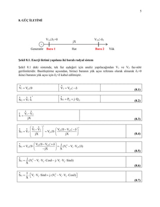
  • 1. 5 8. GÜÇ İLETİMİ Şekil 8.1. Enerji iletimi yapılana iki baralı radyal sistem Şekil 8.1 deki sistemde, tek faz eşdeğeri için analiz yapılacağından V1 ve V2 faz-nötr gerilimleridir. Basitleştirme açısından, birinci baranın yük açısı referans olarak alınarak 1=0 ikinci baranın yük açısı için 2= kabul edilmiştir. 1 1V V 0 2 2V V (8.1) * 112 1S V I 12 12 12S P j Q (8.2) 1 2 1 V V I jX (8.3) 1 2 1 2 12 1 1 V 0 VV V S V V 0 jX jX (8.4) 21 2 12 1 1 1 2 V 0 V j S V 0 (V V V ) jX X (8.5) 2 12 1 1 2 1 2 j S (V V V Cos j V V Sin ) X (8.6) 2 12 1 2 1 1 2 1 S V V Sin j (V V V Cos ) X (8.7) Generatör Bara 1 Hat Bara 2 Yük V1 1=0 jX V2 - 2
  • 2. 6 2 1 2 1 1 2 12 V V (V V V Cos ) S Sin j X X (8.8) 2 1 1 2 12 V V V Q Cos X X (8.9) 1 2 12 V V P Sin X (8.10) (8.10.) İfadesinden anlaşılacağı üzere, birinci baradan ikinci baraya aktif güç iletimi hatbaşı ve hat sonu gerilimlerinin genlikleri ve yük açısı ile doğru orantılı, buna karşılık hattın reaktansı ile ters orantılıdır. 8.2. P - Eğrileri Yük açısı, = 0 o ile 180o arasında değiştirilerek 8.10. denklemine göre P12 hesaplanıp eğrisi çizdirilirse, P- eğrisi elde edilir. Örnek sistem verileri; V1=220 kV, V2=220 kV, X=100 Ohm 0 20 40 60 80 100 120 140 160 180 0 50 100 150 200 250 300 350 400 450 500 AÇI AKTIFGÜÇ(MW) Şekil 8.2. P- eğrisi (V1=V2=220 kV, X=100 Ohm)
  • 3. 7 V1=220 kV, V2=220 kV, X=100 Ohm, ( =30 ) iken 1 2 12 V V 220 220 48400 P Sin Sin(30 ) 0,5 242 MW X 100 100 0 20 40 60 80 100 120 140 160 180 0 50 100 150 200 250 300 350 400 450 500 AÇI (Derece) AKTIFGUC(MW) 242 MW 30 Derece Şekil 8.3. Şekil 8.2. eğrisi üzerinde ( =30 ) yük durumu (P=242 MW) 8.10. denkleminden de görülebileceği gibi ( =90 ) duurmunda maksimum güç transfer edilmektedir. o 90 1 2 12_ max V V P X (8.11) Aynı örnek sistemde; V1=220 kV, V2=220 kV, X=100 Ohm, ( =90 ) iken 1 2 12_ max V V 220 220 48400 P 484 MW X 100 100
  • 4. 8 0 20 40 60 80 100 120 140 160 180 0 50 100 150 200 250 300 350 400 450 500 AÇI (Derece) AKTIFGUC(MW) 242 MW 30 Derece 90 Derece Pmax= 484 MW Şekil 8.3. Şekil 8.2. eğrisi üzerinde ( =30 ) yük durumu ve ( =90 ) maksimum güç durumu (Pmax=484 MW) 8.3. Seri kompanzasyon İletim hatlarına seri kompanzasyon yaparak hattın seri reaktansı küçültülür. Bunun için hattın belli bir yerinde (genellikle hat ortası) iletim hattına seri olarak “kondansatör” ilave edilir. Bu durumda, XL hattın endüktif reaktansı küçülerek (XL- XC) veya (Kd < 1) olarak Kd.(XL- XC) şeklinde ifade edilebilir. 1 2 1 2 12_ max L C d L V V V V P Sin Sin (X X ) K .X (8.12) Örnek : Yukarıdaki örnek sistemde % 40 seri kompanzasyon yapılması durumunda (Kd=0.6); 12_ max 220 220 48400 P xSin(30 ) x0,5 806,6x0,5 403,3MW 0.6x100 60 Maksimum aktif güç = 806 MW, aynı ( =30 ) için taşınabilecek aktif güç ise 403 MW olmuştur. Bir başka yorum; önceki örnekte taşınan 242 MW lık güç ( =17,46 ) açı ile taşınmaktadır.
  • 5. 9 12_ max 220 220 P Sin( ) 242MW 0.6x100 === =17,46 0 20 40 60 80 100 120 140 160 180 0 100 200 300 400 500 600 700 800 900 AÇI (Derece) AKTIFGUC(MW) PB -max PA -max PA PB dAdAB 90 derece Yorumlar : Seri Kompanzasyon yapılması durumunda; 1- Taşınabilecek Maksimum Güç artmaktadır, 2- Aynı ( ) yük açısında daha büyük güç taşınabilmektedir, 3- Aynı güç daha küçük yük açısı ile taşınabilmektedir. Önemli Not : Güç Sistemleri 3 Fazlı olduğu için iletilecek toplam güç için ifade ; 1 2 12 3 V V (P ) 3 Sin X (8.13) Şeklinde olmalıdır.