SlideShare a Scribd company logo
1 of 22
Download to read offline
Part No. 11185SL
Service Manual
ReelmasterR 7000
Preface
The purpose of this publication is to provide the service
technician with information for troubleshooting, testing
and repair of major systems and components on the
Reelmaster 7000.
REFER TO THE TRACTION UNIT AND CUTTING
UNIT OPERATOR’S MANUALS FOR OPERATING,
MAINTENANCE AND ADJUSTMENT INSTRUC-
TIONS. For reference, insert a copy of the Operator’s
Manuals and Parts Catalog for your machine into Chap-
ter 2 of this service manual. Additional copies of the Op-
erator’s Manuals and Parts Catalog are available on the
internet at www.Toro.com.
The Toro Company reserves the right to change product
specifications or this publication without notice.
This safety symbol means DANGER, WARNING
or CAUTION, PERSONAL SAFETY INSTRUC-
TION. When you see this symbol, carefully read
the instructions that follow. Failure to obey the
instructions may result in personal injury.
NOTE: A NOTE will give general information about the
correct operation, maintenance, service, testing or re-
pair of the machine.
IMPORTANT: The IMPORTANT notice will give im-
portant instructions which must be followed to pre-
vent damage to systems or components on the
machine.
E The Toro Company -- 2011
Reelmaster 7000
Table Of Contents
Chapter 1 -- Safety
General Safety Instructions 1 -- 2. . . . . . . . . . . . . . . . . .
Jacking Instructions 1 -- 4. . . . . . . . . . . . . . . . . . . . . . . . .
Safety and Instruction Decals 1 -- 5. . . . . . . . . . . . . . . .
Chapter 2 -- Product Records and Maintenance
Product Records 2 -- 1. . . . . . . . . . . . . . . . . . . . . . . . . . .
Maintenance 2 -- 1. . . . . . . . . . . . . . . . . . . . . . . . . . . . . . .
Equivalents and Conversions 2 -- 2. . . . . . . . . . . . . . . .
Torque Specifications 2 -- 3. . . . . . . . . . . . . . . . . . . . . . .
Chapter 3 -- Kubota Diesel Engine
Specifications 3 -- 2. . . . . . . . . . . . . . . . . . . . . . . . . . . . . .
General Information 3 -- 3. . . . . . . . . . . . . . . . . . . . . . . .
Service and Repairs 3 -- 4. . . . . . . . . . . . . . . . . . . . . . . .
KUBOTA WORKSHOP MANUAL, DIESEL ENGINE,
03--M--DI--E3B SERIES
Chapter 4 -- Hydraulic System
Specifications 4 -- 3. . . . . . . . . . . . . . . . . . . . . . . . . . . . . .
General Information 4 -- 4. . . . . . . . . . . . . . . . . . . . . . . .
Hydraulic Schematic 4 -- 10. . . . . . . . . . . . . . . . . . . . . . .
Hydraulic Flow Diagrams 4 -- 12. . . . . . . . . . . . . . . . . . .
Special Tools 4 -- 26. . . . . . . . . . . . . . . . . . . . . . . . . . . . .
Troubleshooting 4 -- 30. . . . . . . . . . . . . . . . . . . . . . . . . . .
Testing 4 -- 36. . . . . . . . . . . . . . . . . . . . . . . . . . . . . . . . . . .
Adjustments 4 -- 68. . . . . . . . . . . . . . . . . . . . . . . . . . . . . .
Service and Repairs 4 -- 69. . . . . . . . . . . . . . . . . . . . . . .
EATON MODEL 72400 SERVO CONTROLLED PIS-
TON PUMP REPAIR INFORMATION
EATON MODEL 74318 and 74348 PISTON MOTORS:
FIXED DISPLACEMENT, VALVE PLATE DESIGN
REPAIR INFORMATION
SAUER--DANFOSS STEERING UNIT TYPE OSPM
SERVICE MANUAL
Chapter 5 -- Electrical System
General Information 5 -- 2. . . . . . . . . . . . . . . . . . . . . . . .
Electrical Drawings 5 -- 3. . . . . . . . . . . . . . . . . . . . . . . . .
Special Tools 5 -- 4. . . . . . . . . . . . . . . . . . . . . . . . . . . . . .
Troubleshooting 5 -- 6. . . . . . . . . . . . . . . . . . . . . . . . . . . .
Electrical System Quick Checks 5 -- 13. . . . . . . . . . . . .
Adjustments 5 -- 15. . . . . . . . . . . . . . . . . . . . . . . . . . . . . .
Component Testing 5 -- 17. . . . . . . . . . . . . . . . . . . . . . . .
Service and Repairs 5 -- 41. . . . . . . . . . . . . . . . . . . . . . .
Chapter 6 -- Axles, Planetaries and Brakes
Specifications 6 -- 2. . . . . . . . . . . . . . . . . . . . . . . . . . . . . .
General Information 6 -- 3. . . . . . . . . . . . . . . . . . . . . . . .
Service and Repairs 6 -- 4. . . . . . . . . . . . . . . . . . . . . . . .
Chapter 7 -- Chassis
General Information 7 -- 2. . . . . . . . . . . . . . . . . . . . . . . .
Service and Repairs 7 -- 4. . . . . . . . . . . . . . . . . . . . . . . .
Chapter 8 -- DPA Cutting Units
Specifications 8 -- 2. . . . . . . . . . . . . . . . . . . . . . . . . . . . . .
General Information 8 -- 3. . . . . . . . . . . . . . . . . . . . . . . .
Special Tools 8 -- 4. . . . . . . . . . . . . . . . . . . . . . . . . . . . . .
Factors That Can Affect Cutting Performance 8 -- 8. .
Set Up and Adjustments 8 -- 11. . . . . . . . . . . . . . . . . . . .
Service and Repairs 8 -- 14. . . . . . . . . . . . . . . . . . . . . . .
Chapter 9 -- Foldout Drawings
Hydraulic Schematic 9 -- 3. . . . . . . . . . . . . . . . . . . . . . . .
Electrical Schematic 9 -- 4. . . . . . . . . . . . . . . . . . . . . . . .
Wire Harness Drawings 9 -- 6. . . . . . . . . . . . . . . . . . . . .
SafetyProductRecords
andMaintenance
Kubota
DieselEngine
Hydraulic
System
Electrical
System
Axles,Planetaries
andBrakes
DPACuttingChassisFoldout
DrawingsUnits
Reelmaster 7000 Page 1 -- 1 Safety
Chapter 1
Safety
Table of Contents
GENERAL SAFETY INSTRUCTIONS 2. . . . . . . . . . . .
Before Operating 2. . . . . . . . . . . . . . . . . . . . . . . . . . . .
While Operating 2. . . . . . . . . . . . . . . . . . . . . . . . . . . . .
Maintenance and Service 3. . . . . . . . . . . . . . . . . . . .
JACKING INSTRUCTIONS 4. . . . . . . . . . . . . . . . . . . . .
SAFETY AND INSTRUCTION DECALS 5. . . . . . . . . .
Safety
Reelmaster 7000Page 1 -- 2Safety
General Safety Instructions
The Reelmaster 7000 have been tested and certified by
TORO for compliance with existing safety standards
and specifications. Although hazard control and acci-
dent prevention partially are dependent upon the design
and configuration of the machine, these factors are also
dependent upon the awareness, concern and proper
training ofthe personnelinvolved in the operation,trans-
port, maintenance and storage of the machine. Improp-
er use or maintenance of the machine can result in injury
or death. To reduce the potentialfor injury or death,com-
ply with the following safety instructions.
WARNING
To reduce the potential for injury or death,
comply with the following safety instructions.
Before Operating
1. Review and understand the contents of the Opera-
tor’s Manuals and Operator’s DVD before starting and
operating the vehicle. Become familiar with the controls
and know how to stop the vehicle and engine quickly.
Additional copies ofthe Operator’s Manual are available
on the internet at www.Toro.com.
2. Keep all shields, safety devices and decals in place.
If a shield, safety device or decal is defective, illegible or
damaged, repair or replace it before operating the ma-
chine. Also tighten any loose nuts, bolts or screws to en-
sure machine is in safe operating condition.
3. Assure interlock switches are adjusted correctly so
engine cannot be started unless traction pedal is in
NEUTRAL and cutting units are DISENGAGED.
4. Since diesel fuel is flammable, handle it carefully:
A. Use an approved fuel container.
B. Do not remove fuel tank cap while engine is hot or
running.
C. Do not smoke while handling fuel.
D. Fill fuel tank outdoors and only to within an inch of
the top of the tank, not the filler neck. Do not overfill.
E. Wipe up any spilled fuel.
While Operating
1. Sit on the seat when starting and operating the ma-
chine.
2. Before starting the engine:
A. Engage the parking brake.
B. Make sure traction pedal is in neutral and the
PTO switch is OFF (disengaged).
C. After engine is started, release parking brake and
keep foot off traction pedal. Machine must not move.
If movement is evident, the traction pedal linkage is
adjusted incorrectly; therefore, shut engine off and
adjust traction pedal linkage until machine does not
move when traction pedal is released.
3. Do not run engine in a confined area without ade-
quate ventilation. Exhaust fumes are hazardous and
could possibly be deadly.
4. Do not touch engine, exhaust system components or
radiator while engine is running or soon after it is
stopped. These areas could be hot enough to cause
burns.
5. Before getting off the seat:
A. Ensure that traction pedal is in neutral.
B. Engage parking brake.
C. Disengage PTO and wait for cutting unit reel to
stop rotating.
D. Stop engine and remove key from switch.
E. Toro recommends that anytime the machine is
parked (short or long term), the cutting units should
be lowered to the ground. This relieves pressure
from the lift circuit and eliminates the risk of cutting
units accidentally lowering to the ground.
F. Do not park on slopes unless wheels are chocked
or blocked.
Reelmaster 7000 Page 1 -- 3 Safety
Maintenance and Service
1. The Traction Unit and Cutting Unit Operator’s Manu-
als provide information regarding the operation, general
maintenance and maintenance intervals for your Reel-
master machine. Refer to these publications for addi-
tional information when servicing the machine.
2. Before servicing or making adjustments, lower cut-
ting units, stop engine, set parking brake and remove
key from the ignition switch.
3. Make sure machine is in safe operating condition by
keeping all nuts, bolts and screws tight.
4. Never store the machine or fuel container inside
where there is an open flame, such as near a water heat-
er or furnace.
5. Make sure all hydraulic line connectors are tight and
all hydraulic hoses and lines are in good condition be-
fore applying pressure to the hydraulic system.
6. Keep body and hands away frompin hole leaks in hy-
draulic lines that eject high pressure hydraulic fluid. Use
cardboard or paper to find hydraulic leaks. Hydraulic
fluid escaping under pressure can penetrate skin and
cause injury. Fluid accidentally injected into the skin
must be surgically removed within a few hours by a doc-
tor familiar with this form of injury or gangrene may re-
sult.
7. Before disconnecting or performing any work on the
hydraulic system, all pressure in system must be re-
lieved by stopping engine and lowering cutting units to
the ground.
8. If major repairs are ever needed or assistance is de-
sired, contact an Authorized Toro Distributor.
9. To reduce potential fire hazard, keep engine area
free of excessive grease, grass, leaves and dirt. Clean
protective screen on machine frequently.
10.If engine must be running to perform maintenance or
an adjustment, keep hands, feet, clothing and other
parts of the body away from cutting units and other mov-
ing parts. Keep bystanders away.
11.Do not overspeed the engine by changing governor
setting. To assure safety and accuracy, check maximum
engine speed.
12.Shut engine off before checking or adding oil to the
engine crankcase.
13.Disconnect battery before servicing the machine.
Disconnect negative battery cable first and positive
cable last. If battery voltage is required for troubleshoot-
ing or test procedures, temporarily connect the battery.
Reconnect positive battery cable first and negative
cable last.
14.Battery acid is poisonous and can cause burns.
Avoid contact with skin, eyes and clothing. Protect your
face, eyes and clothing when working with a battery.
15.Battery gases can explode. Keep cigarettes, sparks
and flames away from the battery.
16.When welding on machine, disconnect both battery
cables to prevent damage to machine electronic equip-
ment. Disconnect negative battery cable first and posi-
tive cable last. Also, disconnect the wire harness
connector from the machine TEC controller and discon-
nect the terminal connector from the alternator.
17.At the time of manufacture, the machine conformed
to the safety standards for riding mowers. To assure op-
timum performance and continued safety certification of
the machine, use genuine Toro replacement parts and
accessories. Replacement parts and accessories made
by other manufacturers may result in non-conformance
with the safety standards and the warranty may be
voided.
18.When changing attachments, tires or performing
other service, use correct blocks, hoists and jacks.
Make sure machine is parked on a solid level surface
such as a concrete floor. Prior to raising the machine, re-
move any attachments that may interfere with the safe
and proper raising of the machine. Always chock or
block wheels. Use appropriate jack stands to support
the raised machine. If the machine is not properly sup-
ported by jack stands, the machine may move or fall,
which may result in personal injury (see Jacking Instruc-
tions in this chapter).
Safety
Reelmaster 7000Page 1 -- 4Safety
Jacking Instructions
CAUTION
When changing attachments, tires or perform-
ing other service, use correct jacks and sup-
ports. Make sure machine is parked on a solid,
level surface such as a concrete floor. Prior to
raising machine, remove any attachments that
may interfere with the safe and proper raising of
the machine. Always chock orblock wheels.Use
jack stands to support the raised machine. If the
machine is not properly supported by jack
stands, the machine may move or fall, which
may result in personal injury.
Jacking the Front End (Fig. 1)
1. Apply parking brake and chock both rear tires to pre-
vent the machine from moving.
IMPORTANT: Do not place jack, jack stands or
blocks under the wheel motors. Wheel motors can
be damaged if used for jacking or support points.
2. Position jack securely under the frame, just to the in-
side of the front tire.
3. Jack front of machine off the ground.
4. Position appropriate jack stands under the frame as
close to the wheels as possible to support the machine.
Jacking the Rear End (Fig. 2)
1. Apply parking brake and chock both front tires to pre-
vent the machine from moving.
2. Place jack securely under the center of rear axle.
3. Jack rear of machine off the ground.
4. Position appropriate jack stands under the rear axle
to support the machine.
1. Frame 2. Front tire (RH shown)
Figure 1
2
1
1. Rear axle 2. Rear tire (RH shown)
Figure 2
1 2
Reelmaster 7000 Page 1 -- 5 Safety
Safety and Instruction Decals
Numerous safety and instruction decals are affixed to
the Reelmaster 7000. If any decal becomes illegible or
damaged, install a new decal. Decal part numbers are
listed in your Parts Catalog.
Safety
Reelmaster 7000 Page 3 -- 1 Kubota Diesel Engine
Chapter 3
Kubota Diesel Engine
Table of Contents
SPECIFICATIONS 2. . . . . . . . . . . . . . . . . . . . . . . . . . . . .
GENERAL INFORMATION 3. . . . . . . . . . . . . . . . . . . . .
Operator’s Manual 3. . . . . . . . . . . . . . . . . . . . . . . . . .
SERVICE AND REPAIRS 4. . . . . . . . . . . . . . . . . . . . . .
Air Filter System 4. . . . . . . . . . . . . . . . . . . . . . . . . . . .
Exhaust System 6. . . . . . . . . . . . . . . . . . . . . . . . . . . .
Fuel System 8. . . . . . . . . . . . . . . . . . . . . . . . . . . . . . . .
Check Fuel Lines and Connections 9. . . . . . . . . . .
Drain and Clean Fuel Tank 9. . . . . . . . . . . . . . . . . .
Fuel Tank Removal 9. . . . . . . . . . . . . . . . . . . . . . . .
Fuel Tank Installation 9. . . . . . . . . . . . . . . . . . . . . . .
Radiator 10. . . . . . . . . . . . . . . . . . . . . . . . . . . . . . . . . .
Engine 12. . . . . . . . . . . . . . . . . . . . . . . . . . . . . . . . . . . .
Engine Removal 13. . . . . . . . . . . . . . . . . . . . . . . . . .
Engine Installation 14. . . . . . . . . . . . . . . . . . . . . . . .
Pump Adapter Plate 16. . . . . . . . . . . . . . . . . . . . . . . .
KUBOTA WORKSHOP MANUAL, DIESEL ENGINE,
03--M--DI--E3B SERIES
Kubota
DieselEngine
Reelmaster 7000Page 3 -- 2Kubota Diesel Engine
Specifications
Item Description
Make / Designation Kubota Model V2403--M--DI--E3B
4--Cycle, 4 Cylinder, Liquid Cooled, Diesel Engine
Bore 3.425” (87.0 mm)
Stroke 4.031” (102.4 mm)
Total Displacement 148.5 in3 (2434 cc)
Firing Order 1 (closest to gear case end) -- 3 -- 4 (closest to flywheel end) -- 2
Combustion Chamber Spherical Type (E--TVCS)
Compression Ratio 23.2:1
Direction of Rotation Counterclockwise (viewed from flywheel)
Fuel Diesel or Biodiesel (up to B20) Fuel with Low or Ultra Low
Sulfur Content
Fuel Capacity 22 U.S. gallons (83 liters)
Fuel Injection Pump Denso PFR 4M Type Mini Pump
Injection Nozzle Denso OPD Mini Nozzle
Governor Centrifugal Mechanical
Low Idle (no load) 1550 + 50 RPM
High Idle (no load) 2850 +50/--120 RPM
Engine Oil API CH--4, CI--4 or higher
Engine Oil Viscosity See Operator’s Manual
Crankcase Oil Capacity 10.0 U.S. Quarts (9.5 Liters) with Filter
Oil Pump Trochoid Type
Coolant Capacity 13 U.S. Quarts (12.3 Liters)
Starter 12 VDC, 2.0 kW
Alternator/Regulator 12 VDC
Alternator Output 60 amp
Engine Dry Weight 406 U.S. pounds (184 kg)
Reelmaster 7000 Page 3 -- 3 Kubota Diesel Engine
General Information
This Chapter gives information about specifications and
repair of the diesel engine used in the Reelmaster 7000.
General maintenance procedures are described in your
Traction Unit Operator’s Manual. Information on engine
troubleshooting, testing, disassembly and assembly is
identified in the Kubota Workshop Manual, Diesel En-
gine, 03--M--DI--E3B.
Most repairs and adjustments require tools which are
commonly available in many service shops. Special
tools are described in the Kubota Workshop Manual,
Diesel Engine, 03--M--DI--E3B. The use of some spe-
cialized test equipment is explained. However, the cost
of the test equipment and the specialized nature of
some repairs may dictate that the work be done at an en-
gine repair facility.
Service and repair parts for Kubota engines are sup-
plied through your Authorized Toro Distributor. If no
parts listis available,be prepared to provide your distrib-
utor with the Toro model and serial number.
Operator’s Manual
The Traction Unit and Engine Operator’s Manuals pro-
vide information regarding the operation, general main-
tenance and maintenance intervals for your Reelmaster
machine. Refer to these publications for additional infor-
mation when servicing the machine.
Kubota
DieselEngine
Reelmaster 7000Page 3 -- 4Kubota Diesel Engine
Service and Repairs
Air Filter System
Figure 1
1. Battery support
2. Bracket
3. Flange head screw (8 used)
4. Flange nut (8 used)
5. Support bracket
6. Cap screw (4 used)
7. Flange nut (4 used)
8. Fan drive manifold
9. Air cleaner strap
10. Cap screw (2 used)
11. Air cleaner assembly
12. Service indicator
13. Hose clamp
14. Hose clamp
15. Flat washer (2 used)
16. Coolant reservoir
17. Reservoir bracket
18. Flange nut (8 used)
19. Cap screw (2 used)
20. Flange head screw (4 used)
21. Flange head screw (2 used)
22. Hose
23. Adapter
24. Air cleaner hose
25. Reservoir cap
26. Plenum
27. Air intake hose
FRONT
RIGHT
12 to 15 in--lb
(1.4 to 1.6 N--m)
1
2
3
4
10
11
12
13
14
1516
17
5
6
7
8
9
18
19
20
21
22
23
6
18
24
25
Vacuator
Direction
26
27
13
Reelmaster 7000 Page 3 -- 5 Kubota Diesel Engine
Removal (Fig. 1)
1. Park machine on a level surface, lower cutting units,
stop engine, apply parking brake and remove key from
the ignition switch.
2. Raise and support hood.
3. Remove air cleaner components as needed using
Figure 1 as a guide.
Installation (Fig. 1)
IMPORTANT: Any leaks in the air filter system will
cause serious engine damage. Make sure that all air
cleaner components are in good condition and are
properly secured during assembly.
1. Assemble air filter system using Figure 1 as a guide.
A. If service indicator (item 12) was removed from
air cleaner housing, apply thread sealant to adapter
threads before installing adapter and indicator to
housing. Install adapter so that grooves in adapter
hex and adapter filter element are installed toward
service indicator (Fig. 3). Torque indicator from 12 to
15 in--lb (1.4 to 1.6 N--m).
B. Orientate vacuator valve on air cleaner cover to-
ward ground.
C. Installair cleaner so air cleaner strap (item9) isas
close as possible to air cleaner cover.
D. Make sure that air cleaner hose (item 24) does
not contact engine valve cover or other engine com-
ponents. To modify clearance, move and/or rotate air
cleaner body in air cleaner strap. Verify that tabs in
strap mesh fully with slots in air cleaner body.
2. After air cleaner installation is completed, lower and
secure hood.
Figure 2
1. Air cleaner housing
2. Safety filter element
3. Air filter element
4. Air cleaner cover
5. Vacuator valve
1
3
2
4
5
Figure 3
1. Air cleaner assembly
2. Service indicator
3. Adapter
4. Groove
5. Filter element
1
3
2
4
5
Kubota
DieselEngine
Reelmaster 7000Page 3 -- 6Kubota Diesel Engine
Exhaust System
Figure 4
1. Muffler
2. Flange head screw (2 used)
3. Flange head screw (4 used)
4. Muffler clamp
5. Tailpipe
6. RH engine mount
7. Flat washer
8. Cap screw
9. Muffler bracket
10. Muffler gasket
11. Engine
12. Muffler bracket
13. Flange nut (2 used)
14. Muffler clamp
FRONT
RIGHT
1
3
4
6
10
12
5
2
7
8
9
11
13
14
Reelmaster 7000 Page 3 -- 7 Kubota Diesel Engine
Removal (Fig. 4)
CAUTION
The muffler and exhaust pipe may be hot. To
avoid possible burns, allow the engine and ex-
haust system to cool before working on the muf-
fler.
1. Park machine on a level surface, lower cutting units,
stop engine, engage parking brake and remove key
from the ignition switch.
2. Raise and support hood.
3. Remove muffler and/or muffler bracket from the en-
gine as necessary using Figure 4 as a guide.
Installation (Fig. 4)
IMPORTANT: If exhaust studs were removed from
engine cylinder head, thoroughly clean threads in
head and apply Loctite #277 (or equivalent) to stud
threads before installing studs into head.
NOTE: Make sure muffler flange and exhaust manifold
sealing surfaces are free of debris or damage that may
prevent a tight seal.
1. Install new exhaust gasket if original gasket is dam-
aged or torn.
IMPORTANT: Failure to follow the suggested muf-
fler fastener sequence may result in premature muf-
fler failure.
2. Install exhaust system components to the engine us-
ing Figure 4 as a guide. Hand tighten all exhaust system
fasteners before fully tightening any fastener.
3. Tailpipeshouldhaveequalclearance betweenframe
and engine after installation.
4. After exhaust system installation is completed, lower
and secure hood.
Kubota
DieselEngine
Reelmaster 7000Page 3 -- 8Kubota Diesel Engine
Fuel System
Figure 5
1. Fuel suction tube
2. Fuel line clamp (2 used)
3. Fuel hose (supply)
4. Return fitting
5. Fuel hose (return)
6. Fuel tank cap
7. Bushing (2 used)
8. Hose clamp (6 used)
9. Fuel tank
10. Cap screw (2 used)
11. Clamp (2 used)
12. Flange nut (2 used)
13. Fuel pump
14. Washer head screw
15. Fuel pump bracket
16. Fuel hose (supply)
17. Fuel hose (supply)
18. Cap screw (2 used)
19. Flange nut (2 used)
20. Fuel/water separator
21. Elbow fitting (2 used)
22. Flat washer (2 used)
23. Flat washer (2 used)
24. Fuel gauge
25. Grommet
26. Hose clamp
27. Draincock
FRONT
RIGHT
8
9
3
3
4
18
17
16
12
7
1 24
232
22
6
11
10
25
26
21
20
13
27
15
19
14
8
5
8
16
7
21
Reelmaster 7000 Page 3 -- 9 Kubota Diesel Engine
DANGER
Because diesel fuel is flammable, use caution
when storing or handling it. Do not smoke while
filling the fuel tank. Do not fill fuel tank while en-
gine is running, hot or when machine is in an en-
closed area. Always fill fuel tank outside and
wipe up any spilled diesel fuel before starting the
engine. Store fuel in a clean, safety--approved
container and keep cap in place. Use diesel fuel
for the engine only; not for any other purpose.
Check Fuel Lines and Connections
Check fuel lines and connections as recommended in
the Traction Unit Operator’s Manual. Check lines for de-
terioration, damage, leaking or loose connections. Re-
place hoses, clamps and connections as necessary.
Drain and Clean Fuel Tank
Drain and clean the fuel tank periodically as recom-
mended in the Traction Unit Operator’s Manual. Also,
drain and clean the fuel tank if the fuel system becomes
contaminated or if the machine is to be stored for an ex-
tended period. To clean fuel tank, flush tank out with
clean diesel fuel. Make sure tank is free of contaminates
and debris.
Fuel Tank Removal (Fig. 5)
1. Park machine on a level surface, lower cutting units,
stop engine, engage parking brake and remove key
from the ignition switch.
2. Disconnect fuel hoses from the suction and return fit-
tings in top of tank.
3. Use draincock on bottom of tank to empty fuel tank
into a suitable container.
4. Remove fuel tank from machine using Figure 5 as a
guide.
Fuel Tank Installation (Fig. 5)
1. Install fuel tank to frame using Figure 5 as a guide.
2. Connect fuel hoses to the suction and return fittings
in top of tank.
3. Make sure thatdraincock on bottom oftank is closed.
4. Fill fuel tank with clean fuel.
Kubota
DieselEngine
Reelmaster 7000Page 3 -- 10Kubota Diesel Engine
Radiator
Figure 6
1. 90o hydraulic fitting (2 used)
2. Oil cooler
3. Flange nut (4 used)
4. Radiator mount
5. Bulb seal
6. Air cleaner hose
7. Plenum
8. Radiator
9. Hose
10. Hose clamp (3 used)
11. Radiator cap
12. Upper radiator shroud
13. Clamp (4 used)
14. Upper radiator hose
15. Flange nut (12 used)
16. Temperature sender
17. Flat washer (8 used)
18. Flange head screw (11 used)
19. Rubber grommet (2 used)
20. Rubber grommet
21. Flange head screw (4 used)
22. Flange nut (4 used)
23. Foam seal (2 used)
24. Recirculation barrier (2 used)
25. Recirculation barrier bracket (2 used)
26. Screw (2 used)
27. Oil cooler mount plate (2 used)
28. Flange head screw (9 used)
29. O--ring
30. Clamp (2 used)
31. Cap screw (2 used)
32. Washer (2 used)
33. Oil cooler top bracket
34. Bulb seal
35. O--ring
36. R--clamp (2 used)
37. Bushing
38. Elbow fitting
39. Reservoir hose
40. Lower radiator hose
41. Lower radiator shroud
42. Pipe plug
43. Flange head screw (8 used)
44. Flange head screw (4 used)
45. Bulb seal
46. Spacer
FRONT
RIGHT
1
2
3
4
5
6
7
8
9
21
10
11
12
13
14
15
16
17
18
19
20
23
22
25
24
27
26
29
28
15
15
18
10
17
28
3
31
40
41
42
43
44 45
43
30
33 32
35
34
37
36
39
38
46
9 to 11 ft--lb
(12.3 to 14.9 N--m)
Reelmaster 7000 Page 3 -- 11 Kubota Diesel Engine
Removal (Fig. 6)
1. Park machine on a level surface, lower cutting units,
stop engine, engage parking brake and remove key
from the ignition switch.
2. Remove hood from the machine (see Hood Removal
in the Service and Repairs section of Chapter 7 -- Chas-
sis).
CAUTION
Do not open radiator cap or drain coolant if the
radiator or engine is hot. Pressurized, hot cool-
ant can escape and cause burns.
Ethylene--glycol antifreeze is poisonous. Dis-
pose of coolant properly or store it in a properly
labeled container away from children and pets.
3. Remove radiator cap. Drain radiator into a suitable
container using the radiator draincock.
4. Disconnect upper and lower hoses from the radiator.
5. Remove air cleaner hose (item 6).
6. Remove four (4) flange head screws and flange nuts
that secure plenum (item 7) to radiator mount. Remove
plenum.
7. Disconnectreservoir hose(item39)fromtheradiator
vent tube.
8. Detach upper radiator shroud from the radiator and
lower radiator shroud. Remove upper shroud from ma-
chine.
9. Remove fasteners that secure lower radiator shroud
to radiator.
10.Remove six (6) cap screws and flange nuts that se-
cure fan motor bracket to radiator (Fig. 7).
11.Position lower radiator shroud and fan motor bracket
assembly away from radiator.
12.Remove four (4) flange head screws and flange nuts
securing the radiator and recirculation barriers (items 24
and 25) to the radiator mount. Carefully remove barriers
and radiator from the machine.
13.Plug all radiator and hose openings to prevent con-
tamination.
Installation (Fig. 6)
1. Remove plugs placed in radiator and hose openings
during the removal procedure. Make sure that radiator
draincock is closed.
2. Carefully position radiator and recirculation barriers
(items 24 and 25) to the radiator mount. Secure radiator
and barriers in place with four (4) flange head screws
and flange nuts.
3. Position lower radiator shroud and fan motor bracket
assembly to the radiator. Make sure that hydraulic
hoses are correctly positioned in grommets in lower ra-
diator shroud.
4. Secure fan motor bracket to radiator with six (6) cap
screws and flange nuts (Fig. 7).
5. Secure lower radiator shroud to radiator with re-
moved fasteners.
6. Position upper radiator shroud to lower radiator
shroud and radiator. Secure shrouds with removed fas-
teners. Make sure that clearance between shrouds and
fan is at least 0.180” (4.6 mm) at all points.
7. Connect reservoir hose (item 39) to the radiator vent
tube.
8. Connect upper and lower hoses to the radiator.
9. Install plenum (item 7) to radiator mount and secure
with flange head screws and flange nuts.
10.Install air cleaner hose (item 6) to the air cleaner and
plenum.
11.Fill radiator with coolant.
12.Install hood on the machine (see Hood Installation in
the Service and Repairs section of Chapter 7 -- Chas-
sis).
Figure 7
1. Fan
2. Fan motor bracket
3. Fan motor
4. Cap screw (6 used)
5. Flange nut (6 used)
6. Radiator
1
2
3
4
5
6
Kubota
DieselEngine
Thank you very much for
your reading. Please Click
Here. Then Get COMPLETE
MANUAL. NO WAITING
NOTE:
If there is no response to
click on the link above,
please download the PDF
document first and then
click on it.
Reelmaster 7000Page 3 -- 12Kubota Diesel Engine
Engine
Figure 8
1. Muffler
2. Flange head screw
3. Flange head screw (4 used)
4. Muffler clamp
5. Tailpipe
6. RH rear engine mount
7. Cap screw (3 used)
8. RH front engine mount
9. Engine
10. Flange head screw (10 used)
11. Engine mount (4 used)
12. Flange nut (15 used)
13. Rebound washer (4 used)
14. LH front engine mount
15. Lock washer (4 used)
16. Cap screw (4 used)
17. Lock washer (5 used)
18. Cap screw (5 used)
19. LH rear engine mount
20. Muffler bracket
21. Ground wire harness
22. Muffler gasket
23. Cap screw
24. Lock washer
25. Spacer (2 used)
26. Hardened washer (2 used)
27. Lock washer
28. Alternator wire harness
29. Cap screw
30. Flat washer
31. Muffler bracket
32. Flange head screw
33. Muffler clamp
34. Cap screw (2 used)
FRONT
RIGHT
21
28
1
3
4
24
6
7
8
9
11
12
13
14
15
16
17
18
19
20
22
23
27
12
18
17
10
29
12
10
32
5
31
30
33
34
25
26
2
Reelmaster 7000 Page 3 -- 13 Kubota Diesel Engine
Engine Removal (Fig. 8)
1. Park machine on a level surface, lower cutting units,
stop engine, engage parking brake and remove key
from the ignition switch.
2. Remove hood from the machine (see Hood Removal
in the Service and Repairs section of Chapter 7 -- Chas-
sis).
3. Remove battery cover. Disconnect negative battery
cable first and then positive battery cable.
CAUTION
Do not open radiator cap or drain coolant if the
radiator or engine is hot. Pressurized, hot cool-
ant can escape and cause burns.
Ethylene--glycol antifreeze is poisonous. Dis-
pose of coolant properly, or store it in a properly
labeled container away from children and pets.
4. Drain coolant from radiator into a suitable container
(seeRadiatorRemovalin thissection).Disconnectcool-
ant hoses from the radiator.
CAUTION
The exhaust system may be hot. To avoid pos-
sible burns, allow the exhaust system to cool be-
fore working on or near the muffler.
5. Remove exhaust system from engine (see Exhaust
System Removal in this section).
6. Remove air cleaner system from engine (see Air
Cleaner Removal in this section).
7. Note location of cable ties used to secure wire har-
ness. Disconnect wire harness connectors from the fol-
lowing engine components:
A. The engine run solenoid (Fig. 9).
B. The temperature sender (Fig. 10).
C. The alternator (Fig. 10).
D. The glow plug connection.
E. Wire harness connector from engine ground har-
ness.
F. The electric starter motor.
G. Low oil pressure switch located on alternator side
of engine (above electric starter).
Figure 9
1. Engine run solenoid
2. Throttle cable
3. Cable clamp
4. Cable swivel
5. Fuel supply hose
2
1
3
4
5
Figure 10
1. Temperature sender
2. Harness connector
3. Battery cable
2
1 3
8. Disconnect fuel supply hose from injection pump
(Fig. 9). Cap fuel hose and injector pump fuel inlet to pre-
vent contamination.
9. Remove throttle cable from engine (Fig. 9):
A. Remove lock nut that secures throttle cable swiv-
el to speed control lever.
B. Loosen cable clamp and remove throttle cable
from under clamp.
C. Position throttle cable away from the engine.
10.Remove fasteners that secure the upper radiator
shroud to the lower shroud and radiator (see Radiator
Removal in this section). Remove upper radiator shroud
from machine.
Kubota
DieselEngine
Reelmaster 7000Page 3 -- 14Kubota Diesel Engine
11.Remove fan motor and fan assembly (Fig. 11).
A. To prevent contamination of hydraulic system,
thoroughly clean exterior of fan motor and fittings.
B. Disconnect hydraulic hoses from cooling fan mo-
tor. Put caps or plugs on fittings and hoses to prevent
contamination. Label hydraulic lines for proper as-
sembly.
C. Remove six (6) cap screws and flange nuts that
secure fan motor bracket to radiator.
D. Carefully remove fan motor, fan and motor brack-
et assembly from machine.
IMPORTANT: The hydraulic pump assembly can re-
main in machine during engine removal. To prevent
pump assembly from shifting or falling, make sure
to support pump assembly before pump mounting
fasteners are removed.
12.Support hydraulic pump assembly. Remove fasten-
ers that secure piston (traction) pump assembly to en-
gine (see Piston (Traction) Pump Assembly Removal in
the Service and Repairs section of Chapter 4 -- Hydrau-
lic System).
13.Make sure all cable ties securing the wiring harness,
fuel lines or hydraulic hoses to the engine are removed.
14.Connect lift or hoist to the lift tabs on engine.
15.Remove flange nuts, rebound washers and cap
screws that secure the engine mount brackets to the
rubber engine mounts.
CAUTION
One person should operate lift or hoist while a
second person guides the engine out of the ma-
chine.
IMPORTANT: Make sure to not damage the engine,
fuel lines, hydraulic lines, electrical harness or oth-
er parts while removing the engine.
16.Carefully raise engine from the machine.
17.If necessary, remove engine mounts from the engine
using Figure 8 as a guide.
Engine Installation (Fig. 8)
1. Locate machine on a level surface with key removed
from the ignition switch. Chock wheels to keep the ma-
chine from moving.
Figure 11
1
2
3
4
5
6
1. Fan
2. Fan motor bracket
3. Fan motor
4. Cap screw (6 used)
5. Flange nut (6 used)
6. Radiator
2. Make sure that all parts removed from the engine
during maintenance or rebuilding are installed to the en-
gine.
3. If removed, install engine mounts to the engine using
Figure 8 as a guide.
4. Connect lift or hoist to the lift tabs on engine.
CAUTION
One person should operate lift or hoist while a
second person guides the engine into the ma-
chine.
IMPORTANT: Make sure to not damage the engine,
fuel lines, hydraulic lines, electrical harness or oth-
er parts while installing the engine.
5. Carefully lower engine into the machine.
6. Align engine to the rubber engine mounts and hy-
draulic pump input shaft. Secure engine to engine
mounts with cap screws, rebound washers and flange
nuts.
7. Secure hydraulic pump assembly to engine (see Pis-
ton (Traction) Pump Assembly Installation in the Service
and Repairs section of Chapter 4 -- Hydraulic System).

More Related Content

Similar to Toro reelmaster 7000 mower service repair manual

Toro groundsmaster 4010 d (model 30446) service repair manual
Toro groundsmaster 4010 d (model 30446) service repair manualToro groundsmaster 4010 d (model 30446) service repair manual
Toro groundsmaster 4010 d (model 30446) service repair manualfskkkdjskemd
 
Toro groundsmaster 4000 d (model 30448) service repair manual
Toro groundsmaster 4000 d (model 30448) service repair manualToro groundsmaster 4000 d (model 30448) service repair manual
Toro groundsmaster 4000 d (model 30448) service repair manualfskkkdjskemd
 
Toro groundsmaster 4010 d (model 30446) service repair manual
Toro groundsmaster 4010 d (model 30446) service repair manualToro groundsmaster 4010 d (model 30446) service repair manual
Toro groundsmaster 4010 d (model 30446) service repair manualdhjfjkmmmde
 
Toro groundsmaster 4010 d (model 30446) service repair manual
Toro groundsmaster 4010 d (model 30446) service repair manualToro groundsmaster 4010 d (model 30446) service repair manual
Toro groundsmaster 4010 d (model 30446) service repair manualfhsjekkdkem
 
Toro groundsmaster 4000 d (model 30448) service repair manual
Toro groundsmaster 4000 d (model 30448) service repair manualToro groundsmaster 4000 d (model 30448) service repair manual
Toro groundsmaster 4000 d (model 30448) service repair manualfhsjekkdkem
 
Toro groundsmaster 4500 d service repair manual
Toro groundsmaster 4500 d service repair manualToro groundsmaster 4500 d service repair manual
Toro groundsmaster 4500 d service repair manualkfdjkskdmm
 
Toro groundsmaster 4700 d service repair manual
Toro groundsmaster 4700 d service repair manualToro groundsmaster 4700 d service repair manual
Toro groundsmaster 4700 d service repair manualfjskekmmem
 
Toro groundsmaster 4300 d service repair manual
Toro groundsmaster 4300 d service repair manualToro groundsmaster 4300 d service repair manual
Toro groundsmaster 4300 d service repair manualfjjseksxckmdme
 
Toro groundsmaster 4300 d service repair manual
Toro groundsmaster 4300 d service repair manualToro groundsmaster 4300 d service repair manual
Toro groundsmaster 4300 d service repair manualfhsjekdmme
 

Similar to Toro reelmaster 7000 mower service repair manual (9)

Toro groundsmaster 4010 d (model 30446) service repair manual
Toro groundsmaster 4010 d (model 30446) service repair manualToro groundsmaster 4010 d (model 30446) service repair manual
Toro groundsmaster 4010 d (model 30446) service repair manual
 
Toro groundsmaster 4000 d (model 30448) service repair manual
Toro groundsmaster 4000 d (model 30448) service repair manualToro groundsmaster 4000 d (model 30448) service repair manual
Toro groundsmaster 4000 d (model 30448) service repair manual
 
Toro groundsmaster 4010 d (model 30446) service repair manual
Toro groundsmaster 4010 d (model 30446) service repair manualToro groundsmaster 4010 d (model 30446) service repair manual
Toro groundsmaster 4010 d (model 30446) service repair manual
 
Toro groundsmaster 4010 d (model 30446) service repair manual
Toro groundsmaster 4010 d (model 30446) service repair manualToro groundsmaster 4010 d (model 30446) service repair manual
Toro groundsmaster 4010 d (model 30446) service repair manual
 
Toro groundsmaster 4000 d (model 30448) service repair manual
Toro groundsmaster 4000 d (model 30448) service repair manualToro groundsmaster 4000 d (model 30448) service repair manual
Toro groundsmaster 4000 d (model 30448) service repair manual
 
Toro groundsmaster 4500 d service repair manual
Toro groundsmaster 4500 d service repair manualToro groundsmaster 4500 d service repair manual
Toro groundsmaster 4500 d service repair manual
 
Toro groundsmaster 4700 d service repair manual
Toro groundsmaster 4700 d service repair manualToro groundsmaster 4700 d service repair manual
Toro groundsmaster 4700 d service repair manual
 
Toro groundsmaster 4300 d service repair manual
Toro groundsmaster 4300 d service repair manualToro groundsmaster 4300 d service repair manual
Toro groundsmaster 4300 d service repair manual
 
Toro groundsmaster 4300 d service repair manual
Toro groundsmaster 4300 d service repair manualToro groundsmaster 4300 d service repair manual
Toro groundsmaster 4300 d service repair manual
 

More from dhjfjkmmmde

Still r70 80 diesel fork truck service repair manual
Still r70 80 diesel fork truck service repair manualStill r70 80 diesel fork truck service repair manual
Still r70 80 diesel fork truck service repair manualdhjfjkmmmde
 
Still r70 70 diesel fork truck service repair manual
Still r70 70 diesel fork truck service repair manualStill r70 70 diesel fork truck service repair manual
Still r70 70 diesel fork truck service repair manualdhjfjkmmmde
 
Still r70 60 diesel fork truck service repair manual
Still r70 60 diesel fork truck service repair manualStill r70 60 diesel fork truck service repair manual
Still r70 60 diesel fork truck service repair manualdhjfjkmmmde
 
Still r70 45 fork truck service repair manual
Still r70 45 fork truck service repair manualStill r70 45 fork truck service repair manual
Still r70 45 fork truck service repair manualdhjfjkmmmde
 
Still r70 30 fork truck service repair manual
Still r70 30 fork truck service repair manualStill r70 30 fork truck service repair manual
Still r70 30 fork truck service repair manualdhjfjkmmmde
 
Still r70 25 fork truck service repair manual
Still r70 25 fork truck service repair manualStill r70 25 fork truck service repair manual
Still r70 25 fork truck service repair manualdhjfjkmmmde
 
Still r70 20 fork truck service repair manual
Still r70 20 fork truck service repair manualStill r70 20 fork truck service repair manual
Still r70 20 fork truck service repair manualdhjfjkmmmde
 
Still electronic fork truck forklift r50 15 series service repair manual
Still electronic fork truck forklift r50 15 series service repair manualStill electronic fork truck forklift r50 15 series service repair manual
Still electronic fork truck forklift r50 15 series service repair manualdhjfjkmmmde
 
Still electronic fork truck forklift r50 12 series service repair manual
Still electronic fork truck forklift r50 12 series service repair manualStill electronic fork truck forklift r50 12 series service repair manual
Still electronic fork truck forklift r50 12 series service repair manualdhjfjkmmmde
 
Still electronic fork truck forklift r50 10 series service repair manual
Still electronic fork truck forklift r50 10 series service repair manualStill electronic fork truck forklift r50 10 series service repair manual
Still electronic fork truck forklift r50 10 series service repair manualdhjfjkmmmde
 
Kubota l185 f tractor parts catalogue manual
Kubota l185 f tractor parts catalogue manualKubota l185 f tractor parts catalogue manual
Kubota l185 f tractor parts catalogue manualdhjfjkmmmde
 
John deere powertech 4.5 l & 6.8l diesel engines base engine service repa...
John deere powertech 4.5 l & 6.8l diesel engines base engine service repa...John deere powertech 4.5 l & 6.8l diesel engines base engine service repa...
John deere powertech 4.5 l & 6.8l diesel engines base engine service repa...dhjfjkmmmde
 
Husqvarna trimmers service repair manual
Husqvarna trimmers service repair manualHusqvarna trimmers service repair manual
Husqvarna trimmers service repair manualdhjfjkmmmde
 
Husqvarna rider 16 h service repair manual
Husqvarna rider 16 h service repair manualHusqvarna rider 16 h service repair manual
Husqvarna rider 16 h service repair manualdhjfjkmmmde
 
Husqvarna rider 14 pro service repair manual
Husqvarna rider 14 pro service repair manualHusqvarna rider 14 pro service repair manual
Husqvarna rider 14 pro service repair manualdhjfjkmmmde
 
Husqvarna rider 13 h service repair manual
Husqvarna rider 13 h service repair manualHusqvarna rider 13 h service repair manual
Husqvarna rider 13 h service repair manualdhjfjkmmmde
 
Husqvarna rider 13 h bio service repair manual
Husqvarna rider 13 h bio service repair manualHusqvarna rider 13 h bio service repair manual
Husqvarna rider 13 h bio service repair manualdhjfjkmmmde
 
Husqvarna rider 11 service repair manual
Husqvarna rider 11 service repair manualHusqvarna rider 11 service repair manual
Husqvarna rider 11 service repair manualdhjfjkmmmde
 
Husqvarna rider 11 bio service repair manual
Husqvarna rider 11 bio service repair manualHusqvarna rider 11 bio service repair manual
Husqvarna rider 11 bio service repair manualdhjfjkmmmde
 
Husqvarna pruning saws service repair manual
Husqvarna pruning saws service repair manualHusqvarna pruning saws service repair manual
Husqvarna pruning saws service repair manualdhjfjkmmmde
 

More from dhjfjkmmmde (20)

Still r70 80 diesel fork truck service repair manual
Still r70 80 diesel fork truck service repair manualStill r70 80 diesel fork truck service repair manual
Still r70 80 diesel fork truck service repair manual
 
Still r70 70 diesel fork truck service repair manual
Still r70 70 diesel fork truck service repair manualStill r70 70 diesel fork truck service repair manual
Still r70 70 diesel fork truck service repair manual
 
Still r70 60 diesel fork truck service repair manual
Still r70 60 diesel fork truck service repair manualStill r70 60 diesel fork truck service repair manual
Still r70 60 diesel fork truck service repair manual
 
Still r70 45 fork truck service repair manual
Still r70 45 fork truck service repair manualStill r70 45 fork truck service repair manual
Still r70 45 fork truck service repair manual
 
Still r70 30 fork truck service repair manual
Still r70 30 fork truck service repair manualStill r70 30 fork truck service repair manual
Still r70 30 fork truck service repair manual
 
Still r70 25 fork truck service repair manual
Still r70 25 fork truck service repair manualStill r70 25 fork truck service repair manual
Still r70 25 fork truck service repair manual
 
Still r70 20 fork truck service repair manual
Still r70 20 fork truck service repair manualStill r70 20 fork truck service repair manual
Still r70 20 fork truck service repair manual
 
Still electronic fork truck forklift r50 15 series service repair manual
Still electronic fork truck forklift r50 15 series service repair manualStill electronic fork truck forklift r50 15 series service repair manual
Still electronic fork truck forklift r50 15 series service repair manual
 
Still electronic fork truck forklift r50 12 series service repair manual
Still electronic fork truck forklift r50 12 series service repair manualStill electronic fork truck forklift r50 12 series service repair manual
Still electronic fork truck forklift r50 12 series service repair manual
 
Still electronic fork truck forklift r50 10 series service repair manual
Still electronic fork truck forklift r50 10 series service repair manualStill electronic fork truck forklift r50 10 series service repair manual
Still electronic fork truck forklift r50 10 series service repair manual
 
Kubota l185 f tractor parts catalogue manual
Kubota l185 f tractor parts catalogue manualKubota l185 f tractor parts catalogue manual
Kubota l185 f tractor parts catalogue manual
 
John deere powertech 4.5 l & 6.8l diesel engines base engine service repa...
John deere powertech 4.5 l & 6.8l diesel engines base engine service repa...John deere powertech 4.5 l & 6.8l diesel engines base engine service repa...
John deere powertech 4.5 l & 6.8l diesel engines base engine service repa...
 
Husqvarna trimmers service repair manual
Husqvarna trimmers service repair manualHusqvarna trimmers service repair manual
Husqvarna trimmers service repair manual
 
Husqvarna rider 16 h service repair manual
Husqvarna rider 16 h service repair manualHusqvarna rider 16 h service repair manual
Husqvarna rider 16 h service repair manual
 
Husqvarna rider 14 pro service repair manual
Husqvarna rider 14 pro service repair manualHusqvarna rider 14 pro service repair manual
Husqvarna rider 14 pro service repair manual
 
Husqvarna rider 13 h service repair manual
Husqvarna rider 13 h service repair manualHusqvarna rider 13 h service repair manual
Husqvarna rider 13 h service repair manual
 
Husqvarna rider 13 h bio service repair manual
Husqvarna rider 13 h bio service repair manualHusqvarna rider 13 h bio service repair manual
Husqvarna rider 13 h bio service repair manual
 
Husqvarna rider 11 service repair manual
Husqvarna rider 11 service repair manualHusqvarna rider 11 service repair manual
Husqvarna rider 11 service repair manual
 
Husqvarna rider 11 bio service repair manual
Husqvarna rider 11 bio service repair manualHusqvarna rider 11 bio service repair manual
Husqvarna rider 11 bio service repair manual
 
Husqvarna pruning saws service repair manual
Husqvarna pruning saws service repair manualHusqvarna pruning saws service repair manual
Husqvarna pruning saws service repair manual
 

Recently uploaded

What Does The Engine Malfunction Reduced Power Message Mean For Your BMW X5
What Does The Engine Malfunction Reduced Power Message Mean For Your BMW X5What Does The Engine Malfunction Reduced Power Message Mean For Your BMW X5
What Does The Engine Malfunction Reduced Power Message Mean For Your BMW X5Bavarian Workshop
 
如何办理麦考瑞大学毕业证(MQU毕业证书)成绩单原版一比一
如何办理麦考瑞大学毕业证(MQU毕业证书)成绩单原版一比一如何办理麦考瑞大学毕业证(MQU毕业证书)成绩单原版一比一
如何办理麦考瑞大学毕业证(MQU毕业证书)成绩单原版一比一ozave
 
What Could Cause Your Subaru's Touch Screen To Stop Working
What Could Cause Your Subaru's Touch Screen To Stop WorkingWhat Could Cause Your Subaru's Touch Screen To Stop Working
What Could Cause Your Subaru's Touch Screen To Stop WorkingBruce Cox Imports
 
Dubai Call Girls R0yalty O525547819 Call Girls Dubai
Dubai Call Girls R0yalty O525547819 Call Girls DubaiDubai Call Girls R0yalty O525547819 Call Girls Dubai
Dubai Call Girls R0yalty O525547819 Call Girls Dubaikojalkojal131
 
Vip Mumbai Call Girls Navi Mumbai Call On 9920725232 With Body to body massag...
Vip Mumbai Call Girls Navi Mumbai Call On 9920725232 With Body to body massag...Vip Mumbai Call Girls Navi Mumbai Call On 9920725232 With Body to body massag...
Vip Mumbai Call Girls Navi Mumbai Call On 9920725232 With Body to body massag...amitlee9823
 
Bangalore Call Girls: 🍓 7737669865 🍓 High Profile Model Escorts | Bangalore E...
Bangalore Call Girls: 🍓 7737669865 🍓 High Profile Model Escorts | Bangalore E...Bangalore Call Girls: 🍓 7737669865 🍓 High Profile Model Escorts | Bangalore E...
Bangalore Call Girls: 🍓 7737669865 🍓 High Profile Model Escorts | Bangalore E...amitlee9823
 
ENJOY Call Girls In Okhla Vihar Delhi Call 9654467111
ENJOY Call Girls In Okhla Vihar Delhi Call 9654467111ENJOY Call Girls In Okhla Vihar Delhi Call 9654467111
ENJOY Call Girls In Okhla Vihar Delhi Call 9654467111Sapana Sha
 
Sanjay Nagar Call Girls: 🍓 7737669865 🍓 High Profile Model Escorts | Bangalor...
Sanjay Nagar Call Girls: 🍓 7737669865 🍓 High Profile Model Escorts | Bangalor...Sanjay Nagar Call Girls: 🍓 7737669865 🍓 High Profile Model Escorts | Bangalor...
Sanjay Nagar Call Girls: 🍓 7737669865 🍓 High Profile Model Escorts | Bangalor...amitlee9823
 
83778-77756 ( HER.SELF ) Brings Call Girls In Laxmi Nagar
83778-77756 ( HER.SELF ) Brings Call Girls In Laxmi Nagar83778-77756 ( HER.SELF ) Brings Call Girls In Laxmi Nagar
83778-77756 ( HER.SELF ) Brings Call Girls In Laxmi Nagardollysharma2066
 
Vip Mumbai Call Girls Colaba Call On 9920725232 With Body to body massage wit...
Vip Mumbai Call Girls Colaba Call On 9920725232 With Body to body massage wit...Vip Mumbai Call Girls Colaba Call On 9920725232 With Body to body massage wit...
Vip Mumbai Call Girls Colaba Call On 9920725232 With Body to body massage wit...amitlee9823
 
Escorts Service Rajajinagar ☎ 7737669865☎ Book Your One night Stand (Bangalore)
Escorts Service Rajajinagar ☎ 7737669865☎ Book Your One night Stand (Bangalore)Escorts Service Rajajinagar ☎ 7737669865☎ Book Your One night Stand (Bangalore)
Escorts Service Rajajinagar ☎ 7737669865☎ Book Your One night Stand (Bangalore)amitlee9823
 
Lecture-20 Kleene’s Theorem-1.pptx best for understanding the automata
Lecture-20 Kleene’s Theorem-1.pptx best for understanding the automataLecture-20 Kleene’s Theorem-1.pptx best for understanding the automata
Lecture-20 Kleene’s Theorem-1.pptx best for understanding the automataHUSNAINAHMAD39
 
+971565801893>>SAFE AND ORIGINAL ABORTION PILLS FOR SALE IN ABUDHABI,DUBAI MA...
+971565801893>>SAFE AND ORIGINAL ABORTION PILLS FOR SALE IN ABUDHABI,DUBAI MA...+971565801893>>SAFE AND ORIGINAL ABORTION PILLS FOR SALE IN ABUDHABI,DUBAI MA...
+971565801893>>SAFE AND ORIGINAL ABORTION PILLS FOR SALE IN ABUDHABI,DUBAI MA...Health
 
➥🔝 7737669865 🔝▻ narsinghpur Call-girls in Women Seeking Men 🔝narsinghpur🔝 ...
➥🔝 7737669865 🔝▻ narsinghpur Call-girls in Women Seeking Men  🔝narsinghpur🔝  ...➥🔝 7737669865 🔝▻ narsinghpur Call-girls in Women Seeking Men  🔝narsinghpur🔝  ...
➥🔝 7737669865 🔝▻ narsinghpur Call-girls in Women Seeking Men 🔝narsinghpur🔝 ...nirzagarg
 
Call Girls in Malviya Nagar Delhi 💯 Call Us 🔝9205541914 🔝( Delhi) Escorts Ser...
Call Girls in Malviya Nagar Delhi 💯 Call Us 🔝9205541914 🔝( Delhi) Escorts Ser...Call Girls in Malviya Nagar Delhi 💯 Call Us 🔝9205541914 🔝( Delhi) Escorts Ser...
Call Girls in Malviya Nagar Delhi 💯 Call Us 🔝9205541914 🔝( Delhi) Escorts Ser...Delhi Call girls
 
How To Troubleshoot Mercedes Blind Spot Assist Inoperative Error
How To Troubleshoot Mercedes Blind Spot Assist Inoperative ErrorHow To Troubleshoot Mercedes Blind Spot Assist Inoperative Error
How To Troubleshoot Mercedes Blind Spot Assist Inoperative ErrorAndres Auto Service
 

Recently uploaded (20)

What Does The Engine Malfunction Reduced Power Message Mean For Your BMW X5
What Does The Engine Malfunction Reduced Power Message Mean For Your BMW X5What Does The Engine Malfunction Reduced Power Message Mean For Your BMW X5
What Does The Engine Malfunction Reduced Power Message Mean For Your BMW X5
 
如何办理麦考瑞大学毕业证(MQU毕业证书)成绩单原版一比一
如何办理麦考瑞大学毕业证(MQU毕业证书)成绩单原版一比一如何办理麦考瑞大学毕业证(MQU毕业证书)成绩单原版一比一
如何办理麦考瑞大学毕业证(MQU毕业证书)成绩单原版一比一
 
What Could Cause Your Subaru's Touch Screen To Stop Working
What Could Cause Your Subaru's Touch Screen To Stop WorkingWhat Could Cause Your Subaru's Touch Screen To Stop Working
What Could Cause Your Subaru's Touch Screen To Stop Working
 
Dubai Call Girls R0yalty O525547819 Call Girls Dubai
Dubai Call Girls R0yalty O525547819 Call Girls DubaiDubai Call Girls R0yalty O525547819 Call Girls Dubai
Dubai Call Girls R0yalty O525547819 Call Girls Dubai
 
Vip Mumbai Call Girls Navi Mumbai Call On 9920725232 With Body to body massag...
Vip Mumbai Call Girls Navi Mumbai Call On 9920725232 With Body to body massag...Vip Mumbai Call Girls Navi Mumbai Call On 9920725232 With Body to body massag...
Vip Mumbai Call Girls Navi Mumbai Call On 9920725232 With Body to body massag...
 
Call Girls in Patel Nagar, Delhi 💯 Call Us 🔝9953056974 🔝 Escort Service
Call Girls in Patel Nagar, Delhi 💯 Call Us 🔝9953056974 🔝 Escort ServiceCall Girls in Patel Nagar, Delhi 💯 Call Us 🔝9953056974 🔝 Escort Service
Call Girls in Patel Nagar, Delhi 💯 Call Us 🔝9953056974 🔝 Escort Service
 
Bangalore Call Girls: 🍓 7737669865 🍓 High Profile Model Escorts | Bangalore E...
Bangalore Call Girls: 🍓 7737669865 🍓 High Profile Model Escorts | Bangalore E...Bangalore Call Girls: 🍓 7737669865 🍓 High Profile Model Escorts | Bangalore E...
Bangalore Call Girls: 🍓 7737669865 🍓 High Profile Model Escorts | Bangalore E...
 
ENJOY Call Girls In Okhla Vihar Delhi Call 9654467111
ENJOY Call Girls In Okhla Vihar Delhi Call 9654467111ENJOY Call Girls In Okhla Vihar Delhi Call 9654467111
ENJOY Call Girls In Okhla Vihar Delhi Call 9654467111
 
(INDIRA) Call Girl Surat Call Now 8250077686 Surat Escorts 24x7
(INDIRA) Call Girl Surat Call Now 8250077686 Surat Escorts 24x7(INDIRA) Call Girl Surat Call Now 8250077686 Surat Escorts 24x7
(INDIRA) Call Girl Surat Call Now 8250077686 Surat Escorts 24x7
 
Sanjay Nagar Call Girls: 🍓 7737669865 🍓 High Profile Model Escorts | Bangalor...
Sanjay Nagar Call Girls: 🍓 7737669865 🍓 High Profile Model Escorts | Bangalor...Sanjay Nagar Call Girls: 🍓 7737669865 🍓 High Profile Model Escorts | Bangalor...
Sanjay Nagar Call Girls: 🍓 7737669865 🍓 High Profile Model Escorts | Bangalor...
 
83778-77756 ( HER.SELF ) Brings Call Girls In Laxmi Nagar
83778-77756 ( HER.SELF ) Brings Call Girls In Laxmi Nagar83778-77756 ( HER.SELF ) Brings Call Girls In Laxmi Nagar
83778-77756 ( HER.SELF ) Brings Call Girls In Laxmi Nagar
 
Vip Mumbai Call Girls Colaba Call On 9920725232 With Body to body massage wit...
Vip Mumbai Call Girls Colaba Call On 9920725232 With Body to body massage wit...Vip Mumbai Call Girls Colaba Call On 9920725232 With Body to body massage wit...
Vip Mumbai Call Girls Colaba Call On 9920725232 With Body to body massage wit...
 
Escorts Service Rajajinagar ☎ 7737669865☎ Book Your One night Stand (Bangalore)
Escorts Service Rajajinagar ☎ 7737669865☎ Book Your One night Stand (Bangalore)Escorts Service Rajajinagar ☎ 7737669865☎ Book Your One night Stand (Bangalore)
Escorts Service Rajajinagar ☎ 7737669865☎ Book Your One night Stand (Bangalore)
 
(INDIRA) Call Girl Nashik Call Now 8617697112 Nashik Escorts 24x7
(INDIRA) Call Girl Nashik Call Now 8617697112 Nashik Escorts 24x7(INDIRA) Call Girl Nashik Call Now 8617697112 Nashik Escorts 24x7
(INDIRA) Call Girl Nashik Call Now 8617697112 Nashik Escorts 24x7
 
Lecture-20 Kleene’s Theorem-1.pptx best for understanding the automata
Lecture-20 Kleene’s Theorem-1.pptx best for understanding the automataLecture-20 Kleene’s Theorem-1.pptx best for understanding the automata
Lecture-20 Kleene’s Theorem-1.pptx best for understanding the automata
 
+971565801893>>SAFE AND ORIGINAL ABORTION PILLS FOR SALE IN ABUDHABI,DUBAI MA...
+971565801893>>SAFE AND ORIGINAL ABORTION PILLS FOR SALE IN ABUDHABI,DUBAI MA...+971565801893>>SAFE AND ORIGINAL ABORTION PILLS FOR SALE IN ABUDHABI,DUBAI MA...
+971565801893>>SAFE AND ORIGINAL ABORTION PILLS FOR SALE IN ABUDHABI,DUBAI MA...
 
➥🔝 7737669865 🔝▻ narsinghpur Call-girls in Women Seeking Men 🔝narsinghpur🔝 ...
➥🔝 7737669865 🔝▻ narsinghpur Call-girls in Women Seeking Men  🔝narsinghpur🔝  ...➥🔝 7737669865 🔝▻ narsinghpur Call-girls in Women Seeking Men  🔝narsinghpur🔝  ...
➥🔝 7737669865 🔝▻ narsinghpur Call-girls in Women Seeking Men 🔝narsinghpur🔝 ...
 
(ISHITA) Call Girls Service Jammu Call Now 8617697112 Jammu Escorts 24x7
(ISHITA) Call Girls Service Jammu Call Now 8617697112 Jammu Escorts 24x7(ISHITA) Call Girls Service Jammu Call Now 8617697112 Jammu Escorts 24x7
(ISHITA) Call Girls Service Jammu Call Now 8617697112 Jammu Escorts 24x7
 
Call Girls in Malviya Nagar Delhi 💯 Call Us 🔝9205541914 🔝( Delhi) Escorts Ser...
Call Girls in Malviya Nagar Delhi 💯 Call Us 🔝9205541914 🔝( Delhi) Escorts Ser...Call Girls in Malviya Nagar Delhi 💯 Call Us 🔝9205541914 🔝( Delhi) Escorts Ser...
Call Girls in Malviya Nagar Delhi 💯 Call Us 🔝9205541914 🔝( Delhi) Escorts Ser...
 
How To Troubleshoot Mercedes Blind Spot Assist Inoperative Error
How To Troubleshoot Mercedes Blind Spot Assist Inoperative ErrorHow To Troubleshoot Mercedes Blind Spot Assist Inoperative Error
How To Troubleshoot Mercedes Blind Spot Assist Inoperative Error
 

Toro reelmaster 7000 mower service repair manual

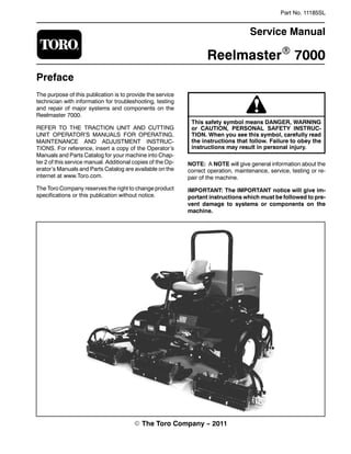
  • 1. Part No. 11185SL Service Manual ReelmasterR 7000 Preface The purpose of this publication is to provide the service technician with information for troubleshooting, testing and repair of major systems and components on the Reelmaster 7000. REFER TO THE TRACTION UNIT AND CUTTING UNIT OPERATOR’S MANUALS FOR OPERATING, MAINTENANCE AND ADJUSTMENT INSTRUC- TIONS. For reference, insert a copy of the Operator’s Manuals and Parts Catalog for your machine into Chap- ter 2 of this service manual. Additional copies of the Op- erator’s Manuals and Parts Catalog are available on the internet at www.Toro.com. The Toro Company reserves the right to change product specifications or this publication without notice. This safety symbol means DANGER, WARNING or CAUTION, PERSONAL SAFETY INSTRUC- TION. When you see this symbol, carefully read the instructions that follow. Failure to obey the instructions may result in personal injury. NOTE: A NOTE will give general information about the correct operation, maintenance, service, testing or re- pair of the machine. IMPORTANT: The IMPORTANT notice will give im- portant instructions which must be followed to pre- vent damage to systems or components on the machine. E The Toro Company -- 2011
  • 2. Reelmaster 7000 Table Of Contents Chapter 1 -- Safety General Safety Instructions 1 -- 2. . . . . . . . . . . . . . . . . . Jacking Instructions 1 -- 4. . . . . . . . . . . . . . . . . . . . . . . . . Safety and Instruction Decals 1 -- 5. . . . . . . . . . . . . . . . Chapter 2 -- Product Records and Maintenance Product Records 2 -- 1. . . . . . . . . . . . . . . . . . . . . . . . . . . Maintenance 2 -- 1. . . . . . . . . . . . . . . . . . . . . . . . . . . . . . . Equivalents and Conversions 2 -- 2. . . . . . . . . . . . . . . . Torque Specifications 2 -- 3. . . . . . . . . . . . . . . . . . . . . . . Chapter 3 -- Kubota Diesel Engine Specifications 3 -- 2. . . . . . . . . . . . . . . . . . . . . . . . . . . . . . General Information 3 -- 3. . . . . . . . . . . . . . . . . . . . . . . . Service and Repairs 3 -- 4. . . . . . . . . . . . . . . . . . . . . . . . KUBOTA WORKSHOP MANUAL, DIESEL ENGINE, 03--M--DI--E3B SERIES Chapter 4 -- Hydraulic System Specifications 4 -- 3. . . . . . . . . . . . . . . . . . . . . . . . . . . . . . General Information 4 -- 4. . . . . . . . . . . . . . . . . . . . . . . . Hydraulic Schematic 4 -- 10. . . . . . . . . . . . . . . . . . . . . . . Hydraulic Flow Diagrams 4 -- 12. . . . . . . . . . . . . . . . . . . Special Tools 4 -- 26. . . . . . . . . . . . . . . . . . . . . . . . . . . . . Troubleshooting 4 -- 30. . . . . . . . . . . . . . . . . . . . . . . . . . . Testing 4 -- 36. . . . . . . . . . . . . . . . . . . . . . . . . . . . . . . . . . . Adjustments 4 -- 68. . . . . . . . . . . . . . . . . . . . . . . . . . . . . . Service and Repairs 4 -- 69. . . . . . . . . . . . . . . . . . . . . . . EATON MODEL 72400 SERVO CONTROLLED PIS- TON PUMP REPAIR INFORMATION EATON MODEL 74318 and 74348 PISTON MOTORS: FIXED DISPLACEMENT, VALVE PLATE DESIGN REPAIR INFORMATION SAUER--DANFOSS STEERING UNIT TYPE OSPM SERVICE MANUAL Chapter 5 -- Electrical System General Information 5 -- 2. . . . . . . . . . . . . . . . . . . . . . . . Electrical Drawings 5 -- 3. . . . . . . . . . . . . . . . . . . . . . . . . Special Tools 5 -- 4. . . . . . . . . . . . . . . . . . . . . . . . . . . . . . Troubleshooting 5 -- 6. . . . . . . . . . . . . . . . . . . . . . . . . . . . Electrical System Quick Checks 5 -- 13. . . . . . . . . . . . . Adjustments 5 -- 15. . . . . . . . . . . . . . . . . . . . . . . . . . . . . . Component Testing 5 -- 17. . . . . . . . . . . . . . . . . . . . . . . . Service and Repairs 5 -- 41. . . . . . . . . . . . . . . . . . . . . . . Chapter 6 -- Axles, Planetaries and Brakes Specifications 6 -- 2. . . . . . . . . . . . . . . . . . . . . . . . . . . . . . General Information 6 -- 3. . . . . . . . . . . . . . . . . . . . . . . . Service and Repairs 6 -- 4. . . . . . . . . . . . . . . . . . . . . . . . Chapter 7 -- Chassis General Information 7 -- 2. . . . . . . . . . . . . . . . . . . . . . . . Service and Repairs 7 -- 4. . . . . . . . . . . . . . . . . . . . . . . . Chapter 8 -- DPA Cutting Units Specifications 8 -- 2. . . . . . . . . . . . . . . . . . . . . . . . . . . . . . General Information 8 -- 3. . . . . . . . . . . . . . . . . . . . . . . . Special Tools 8 -- 4. . . . . . . . . . . . . . . . . . . . . . . . . . . . . . Factors That Can Affect Cutting Performance 8 -- 8. . Set Up and Adjustments 8 -- 11. . . . . . . . . . . . . . . . . . . . Service and Repairs 8 -- 14. . . . . . . . . . . . . . . . . . . . . . . Chapter 9 -- Foldout Drawings Hydraulic Schematic 9 -- 3. . . . . . . . . . . . . . . . . . . . . . . . Electrical Schematic 9 -- 4. . . . . . . . . . . . . . . . . . . . . . . . Wire Harness Drawings 9 -- 6. . . . . . . . . . . . . . . . . . . . . SafetyProductRecords andMaintenance Kubota DieselEngine Hydraulic System Electrical System Axles,Planetaries andBrakes DPACuttingChassisFoldout DrawingsUnits
  • 3. Reelmaster 7000 Page 1 -- 1 Safety Chapter 1 Safety Table of Contents GENERAL SAFETY INSTRUCTIONS 2. . . . . . . . . . . . Before Operating 2. . . . . . . . . . . . . . . . . . . . . . . . . . . . While Operating 2. . . . . . . . . . . . . . . . . . . . . . . . . . . . . Maintenance and Service 3. . . . . . . . . . . . . . . . . . . . JACKING INSTRUCTIONS 4. . . . . . . . . . . . . . . . . . . . . SAFETY AND INSTRUCTION DECALS 5. . . . . . . . . . Safety
  • 4. Reelmaster 7000Page 1 -- 2Safety General Safety Instructions The Reelmaster 7000 have been tested and certified by TORO for compliance with existing safety standards and specifications. Although hazard control and acci- dent prevention partially are dependent upon the design and configuration of the machine, these factors are also dependent upon the awareness, concern and proper training ofthe personnelinvolved in the operation,trans- port, maintenance and storage of the machine. Improp- er use or maintenance of the machine can result in injury or death. To reduce the potentialfor injury or death,com- ply with the following safety instructions. WARNING To reduce the potential for injury or death, comply with the following safety instructions. Before Operating 1. Review and understand the contents of the Opera- tor’s Manuals and Operator’s DVD before starting and operating the vehicle. Become familiar with the controls and know how to stop the vehicle and engine quickly. Additional copies ofthe Operator’s Manual are available on the internet at www.Toro.com. 2. Keep all shields, safety devices and decals in place. If a shield, safety device or decal is defective, illegible or damaged, repair or replace it before operating the ma- chine. Also tighten any loose nuts, bolts or screws to en- sure machine is in safe operating condition. 3. Assure interlock switches are adjusted correctly so engine cannot be started unless traction pedal is in NEUTRAL and cutting units are DISENGAGED. 4. Since diesel fuel is flammable, handle it carefully: A. Use an approved fuel container. B. Do not remove fuel tank cap while engine is hot or running. C. Do not smoke while handling fuel. D. Fill fuel tank outdoors and only to within an inch of the top of the tank, not the filler neck. Do not overfill. E. Wipe up any spilled fuel. While Operating 1. Sit on the seat when starting and operating the ma- chine. 2. Before starting the engine: A. Engage the parking brake. B. Make sure traction pedal is in neutral and the PTO switch is OFF (disengaged). C. After engine is started, release parking brake and keep foot off traction pedal. Machine must not move. If movement is evident, the traction pedal linkage is adjusted incorrectly; therefore, shut engine off and adjust traction pedal linkage until machine does not move when traction pedal is released. 3. Do not run engine in a confined area without ade- quate ventilation. Exhaust fumes are hazardous and could possibly be deadly. 4. Do not touch engine, exhaust system components or radiator while engine is running or soon after it is stopped. These areas could be hot enough to cause burns. 5. Before getting off the seat: A. Ensure that traction pedal is in neutral. B. Engage parking brake. C. Disengage PTO and wait for cutting unit reel to stop rotating. D. Stop engine and remove key from switch. E. Toro recommends that anytime the machine is parked (short or long term), the cutting units should be lowered to the ground. This relieves pressure from the lift circuit and eliminates the risk of cutting units accidentally lowering to the ground. F. Do not park on slopes unless wheels are chocked or blocked.
  • 5. Reelmaster 7000 Page 1 -- 3 Safety Maintenance and Service 1. The Traction Unit and Cutting Unit Operator’s Manu- als provide information regarding the operation, general maintenance and maintenance intervals for your Reel- master machine. Refer to these publications for addi- tional information when servicing the machine. 2. Before servicing or making adjustments, lower cut- ting units, stop engine, set parking brake and remove key from the ignition switch. 3. Make sure machine is in safe operating condition by keeping all nuts, bolts and screws tight. 4. Never store the machine or fuel container inside where there is an open flame, such as near a water heat- er or furnace. 5. Make sure all hydraulic line connectors are tight and all hydraulic hoses and lines are in good condition be- fore applying pressure to the hydraulic system. 6. Keep body and hands away frompin hole leaks in hy- draulic lines that eject high pressure hydraulic fluid. Use cardboard or paper to find hydraulic leaks. Hydraulic fluid escaping under pressure can penetrate skin and cause injury. Fluid accidentally injected into the skin must be surgically removed within a few hours by a doc- tor familiar with this form of injury or gangrene may re- sult. 7. Before disconnecting or performing any work on the hydraulic system, all pressure in system must be re- lieved by stopping engine and lowering cutting units to the ground. 8. If major repairs are ever needed or assistance is de- sired, contact an Authorized Toro Distributor. 9. To reduce potential fire hazard, keep engine area free of excessive grease, grass, leaves and dirt. Clean protective screen on machine frequently. 10.If engine must be running to perform maintenance or an adjustment, keep hands, feet, clothing and other parts of the body away from cutting units and other mov- ing parts. Keep bystanders away. 11.Do not overspeed the engine by changing governor setting. To assure safety and accuracy, check maximum engine speed. 12.Shut engine off before checking or adding oil to the engine crankcase. 13.Disconnect battery before servicing the machine. Disconnect negative battery cable first and positive cable last. If battery voltage is required for troubleshoot- ing or test procedures, temporarily connect the battery. Reconnect positive battery cable first and negative cable last. 14.Battery acid is poisonous and can cause burns. Avoid contact with skin, eyes and clothing. Protect your face, eyes and clothing when working with a battery. 15.Battery gases can explode. Keep cigarettes, sparks and flames away from the battery. 16.When welding on machine, disconnect both battery cables to prevent damage to machine electronic equip- ment. Disconnect negative battery cable first and posi- tive cable last. Also, disconnect the wire harness connector from the machine TEC controller and discon- nect the terminal connector from the alternator. 17.At the time of manufacture, the machine conformed to the safety standards for riding mowers. To assure op- timum performance and continued safety certification of the machine, use genuine Toro replacement parts and accessories. Replacement parts and accessories made by other manufacturers may result in non-conformance with the safety standards and the warranty may be voided. 18.When changing attachments, tires or performing other service, use correct blocks, hoists and jacks. Make sure machine is parked on a solid level surface such as a concrete floor. Prior to raising the machine, re- move any attachments that may interfere with the safe and proper raising of the machine. Always chock or block wheels. Use appropriate jack stands to support the raised machine. If the machine is not properly sup- ported by jack stands, the machine may move or fall, which may result in personal injury (see Jacking Instruc- tions in this chapter). Safety
  • 6. Reelmaster 7000Page 1 -- 4Safety Jacking Instructions CAUTION When changing attachments, tires or perform- ing other service, use correct jacks and sup- ports. Make sure machine is parked on a solid, level surface such as a concrete floor. Prior to raising machine, remove any attachments that may interfere with the safe and proper raising of the machine. Always chock orblock wheels.Use jack stands to support the raised machine. If the machine is not properly supported by jack stands, the machine may move or fall, which may result in personal injury. Jacking the Front End (Fig. 1) 1. Apply parking brake and chock both rear tires to pre- vent the machine from moving. IMPORTANT: Do not place jack, jack stands or blocks under the wheel motors. Wheel motors can be damaged if used for jacking or support points. 2. Position jack securely under the frame, just to the in- side of the front tire. 3. Jack front of machine off the ground. 4. Position appropriate jack stands under the frame as close to the wheels as possible to support the machine. Jacking the Rear End (Fig. 2) 1. Apply parking brake and chock both front tires to pre- vent the machine from moving. 2. Place jack securely under the center of rear axle. 3. Jack rear of machine off the ground. 4. Position appropriate jack stands under the rear axle to support the machine. 1. Frame 2. Front tire (RH shown) Figure 1 2 1 1. Rear axle 2. Rear tire (RH shown) Figure 2 1 2
  • 7. Reelmaster 7000 Page 1 -- 5 Safety Safety and Instruction Decals Numerous safety and instruction decals are affixed to the Reelmaster 7000. If any decal becomes illegible or damaged, install a new decal. Decal part numbers are listed in your Parts Catalog. Safety
  • 8. Reelmaster 7000 Page 3 -- 1 Kubota Diesel Engine Chapter 3 Kubota Diesel Engine Table of Contents SPECIFICATIONS 2. . . . . . . . . . . . . . . . . . . . . . . . . . . . . GENERAL INFORMATION 3. . . . . . . . . . . . . . . . . . . . . Operator’s Manual 3. . . . . . . . . . . . . . . . . . . . . . . . . . SERVICE AND REPAIRS 4. . . . . . . . . . . . . . . . . . . . . . Air Filter System 4. . . . . . . . . . . . . . . . . . . . . . . . . . . . Exhaust System 6. . . . . . . . . . . . . . . . . . . . . . . . . . . . Fuel System 8. . . . . . . . . . . . . . . . . . . . . . . . . . . . . . . . Check Fuel Lines and Connections 9. . . . . . . . . . . Drain and Clean Fuel Tank 9. . . . . . . . . . . . . . . . . . Fuel Tank Removal 9. . . . . . . . . . . . . . . . . . . . . . . . Fuel Tank Installation 9. . . . . . . . . . . . . . . . . . . . . . . Radiator 10. . . . . . . . . . . . . . . . . . . . . . . . . . . . . . . . . . Engine 12. . . . . . . . . . . . . . . . . . . . . . . . . . . . . . . . . . . . Engine Removal 13. . . . . . . . . . . . . . . . . . . . . . . . . . Engine Installation 14. . . . . . . . . . . . . . . . . . . . . . . . Pump Adapter Plate 16. . . . . . . . . . . . . . . . . . . . . . . . KUBOTA WORKSHOP MANUAL, DIESEL ENGINE, 03--M--DI--E3B SERIES Kubota DieselEngine
  • 9. Reelmaster 7000Page 3 -- 2Kubota Diesel Engine Specifications Item Description Make / Designation Kubota Model V2403--M--DI--E3B 4--Cycle, 4 Cylinder, Liquid Cooled, Diesel Engine Bore 3.425” (87.0 mm) Stroke 4.031” (102.4 mm) Total Displacement 148.5 in3 (2434 cc) Firing Order 1 (closest to gear case end) -- 3 -- 4 (closest to flywheel end) -- 2 Combustion Chamber Spherical Type (E--TVCS) Compression Ratio 23.2:1 Direction of Rotation Counterclockwise (viewed from flywheel) Fuel Diesel or Biodiesel (up to B20) Fuel with Low or Ultra Low Sulfur Content Fuel Capacity 22 U.S. gallons (83 liters) Fuel Injection Pump Denso PFR 4M Type Mini Pump Injection Nozzle Denso OPD Mini Nozzle Governor Centrifugal Mechanical Low Idle (no load) 1550 + 50 RPM High Idle (no load) 2850 +50/--120 RPM Engine Oil API CH--4, CI--4 or higher Engine Oil Viscosity See Operator’s Manual Crankcase Oil Capacity 10.0 U.S. Quarts (9.5 Liters) with Filter Oil Pump Trochoid Type Coolant Capacity 13 U.S. Quarts (12.3 Liters) Starter 12 VDC, 2.0 kW Alternator/Regulator 12 VDC Alternator Output 60 amp Engine Dry Weight 406 U.S. pounds (184 kg)
  • 10. Reelmaster 7000 Page 3 -- 3 Kubota Diesel Engine General Information This Chapter gives information about specifications and repair of the diesel engine used in the Reelmaster 7000. General maintenance procedures are described in your Traction Unit Operator’s Manual. Information on engine troubleshooting, testing, disassembly and assembly is identified in the Kubota Workshop Manual, Diesel En- gine, 03--M--DI--E3B. Most repairs and adjustments require tools which are commonly available in many service shops. Special tools are described in the Kubota Workshop Manual, Diesel Engine, 03--M--DI--E3B. The use of some spe- cialized test equipment is explained. However, the cost of the test equipment and the specialized nature of some repairs may dictate that the work be done at an en- gine repair facility. Service and repair parts for Kubota engines are sup- plied through your Authorized Toro Distributor. If no parts listis available,be prepared to provide your distrib- utor with the Toro model and serial number. Operator’s Manual The Traction Unit and Engine Operator’s Manuals pro- vide information regarding the operation, general main- tenance and maintenance intervals for your Reelmaster machine. Refer to these publications for additional infor- mation when servicing the machine. Kubota DieselEngine
  • 11. Reelmaster 7000Page 3 -- 4Kubota Diesel Engine Service and Repairs Air Filter System Figure 1 1. Battery support 2. Bracket 3. Flange head screw (8 used) 4. Flange nut (8 used) 5. Support bracket 6. Cap screw (4 used) 7. Flange nut (4 used) 8. Fan drive manifold 9. Air cleaner strap 10. Cap screw (2 used) 11. Air cleaner assembly 12. Service indicator 13. Hose clamp 14. Hose clamp 15. Flat washer (2 used) 16. Coolant reservoir 17. Reservoir bracket 18. Flange nut (8 used) 19. Cap screw (2 used) 20. Flange head screw (4 used) 21. Flange head screw (2 used) 22. Hose 23. Adapter 24. Air cleaner hose 25. Reservoir cap 26. Plenum 27. Air intake hose FRONT RIGHT 12 to 15 in--lb (1.4 to 1.6 N--m) 1 2 3 4 10 11 12 13 14 1516 17 5 6 7 8 9 18 19 20 21 22 23 6 18 24 25 Vacuator Direction 26 27 13
  • 12. Reelmaster 7000 Page 3 -- 5 Kubota Diesel Engine Removal (Fig. 1) 1. Park machine on a level surface, lower cutting units, stop engine, apply parking brake and remove key from the ignition switch. 2. Raise and support hood. 3. Remove air cleaner components as needed using Figure 1 as a guide. Installation (Fig. 1) IMPORTANT: Any leaks in the air filter system will cause serious engine damage. Make sure that all air cleaner components are in good condition and are properly secured during assembly. 1. Assemble air filter system using Figure 1 as a guide. A. If service indicator (item 12) was removed from air cleaner housing, apply thread sealant to adapter threads before installing adapter and indicator to housing. Install adapter so that grooves in adapter hex and adapter filter element are installed toward service indicator (Fig. 3). Torque indicator from 12 to 15 in--lb (1.4 to 1.6 N--m). B. Orientate vacuator valve on air cleaner cover to- ward ground. C. Installair cleaner so air cleaner strap (item9) isas close as possible to air cleaner cover. D. Make sure that air cleaner hose (item 24) does not contact engine valve cover or other engine com- ponents. To modify clearance, move and/or rotate air cleaner body in air cleaner strap. Verify that tabs in strap mesh fully with slots in air cleaner body. 2. After air cleaner installation is completed, lower and secure hood. Figure 2 1. Air cleaner housing 2. Safety filter element 3. Air filter element 4. Air cleaner cover 5. Vacuator valve 1 3 2 4 5 Figure 3 1. Air cleaner assembly 2. Service indicator 3. Adapter 4. Groove 5. Filter element 1 3 2 4 5 Kubota DieselEngine
  • 13. Reelmaster 7000Page 3 -- 6Kubota Diesel Engine Exhaust System Figure 4 1. Muffler 2. Flange head screw (2 used) 3. Flange head screw (4 used) 4. Muffler clamp 5. Tailpipe 6. RH engine mount 7. Flat washer 8. Cap screw 9. Muffler bracket 10. Muffler gasket 11. Engine 12. Muffler bracket 13. Flange nut (2 used) 14. Muffler clamp FRONT RIGHT 1 3 4 6 10 12 5 2 7 8 9 11 13 14
  • 14. Reelmaster 7000 Page 3 -- 7 Kubota Diesel Engine Removal (Fig. 4) CAUTION The muffler and exhaust pipe may be hot. To avoid possible burns, allow the engine and ex- haust system to cool before working on the muf- fler. 1. Park machine on a level surface, lower cutting units, stop engine, engage parking brake and remove key from the ignition switch. 2. Raise and support hood. 3. Remove muffler and/or muffler bracket from the en- gine as necessary using Figure 4 as a guide. Installation (Fig. 4) IMPORTANT: If exhaust studs were removed from engine cylinder head, thoroughly clean threads in head and apply Loctite #277 (or equivalent) to stud threads before installing studs into head. NOTE: Make sure muffler flange and exhaust manifold sealing surfaces are free of debris or damage that may prevent a tight seal. 1. Install new exhaust gasket if original gasket is dam- aged or torn. IMPORTANT: Failure to follow the suggested muf- fler fastener sequence may result in premature muf- fler failure. 2. Install exhaust system components to the engine us- ing Figure 4 as a guide. Hand tighten all exhaust system fasteners before fully tightening any fastener. 3. Tailpipeshouldhaveequalclearance betweenframe and engine after installation. 4. After exhaust system installation is completed, lower and secure hood. Kubota DieselEngine
  • 15. Reelmaster 7000Page 3 -- 8Kubota Diesel Engine Fuel System Figure 5 1. Fuel suction tube 2. Fuel line clamp (2 used) 3. Fuel hose (supply) 4. Return fitting 5. Fuel hose (return) 6. Fuel tank cap 7. Bushing (2 used) 8. Hose clamp (6 used) 9. Fuel tank 10. Cap screw (2 used) 11. Clamp (2 used) 12. Flange nut (2 used) 13. Fuel pump 14. Washer head screw 15. Fuel pump bracket 16. Fuel hose (supply) 17. Fuel hose (supply) 18. Cap screw (2 used) 19. Flange nut (2 used) 20. Fuel/water separator 21. Elbow fitting (2 used) 22. Flat washer (2 used) 23. Flat washer (2 used) 24. Fuel gauge 25. Grommet 26. Hose clamp 27. Draincock FRONT RIGHT 8 9 3 3 4 18 17 16 12 7 1 24 232 22 6 11 10 25 26 21 20 13 27 15 19 14 8 5 8 16 7 21
  • 16. Reelmaster 7000 Page 3 -- 9 Kubota Diesel Engine DANGER Because diesel fuel is flammable, use caution when storing or handling it. Do not smoke while filling the fuel tank. Do not fill fuel tank while en- gine is running, hot or when machine is in an en- closed area. Always fill fuel tank outside and wipe up any spilled diesel fuel before starting the engine. Store fuel in a clean, safety--approved container and keep cap in place. Use diesel fuel for the engine only; not for any other purpose. Check Fuel Lines and Connections Check fuel lines and connections as recommended in the Traction Unit Operator’s Manual. Check lines for de- terioration, damage, leaking or loose connections. Re- place hoses, clamps and connections as necessary. Drain and Clean Fuel Tank Drain and clean the fuel tank periodically as recom- mended in the Traction Unit Operator’s Manual. Also, drain and clean the fuel tank if the fuel system becomes contaminated or if the machine is to be stored for an ex- tended period. To clean fuel tank, flush tank out with clean diesel fuel. Make sure tank is free of contaminates and debris. Fuel Tank Removal (Fig. 5) 1. Park machine on a level surface, lower cutting units, stop engine, engage parking brake and remove key from the ignition switch. 2. Disconnect fuel hoses from the suction and return fit- tings in top of tank. 3. Use draincock on bottom of tank to empty fuel tank into a suitable container. 4. Remove fuel tank from machine using Figure 5 as a guide. Fuel Tank Installation (Fig. 5) 1. Install fuel tank to frame using Figure 5 as a guide. 2. Connect fuel hoses to the suction and return fittings in top of tank. 3. Make sure thatdraincock on bottom oftank is closed. 4. Fill fuel tank with clean fuel. Kubota DieselEngine
  • 17. Reelmaster 7000Page 3 -- 10Kubota Diesel Engine Radiator Figure 6 1. 90o hydraulic fitting (2 used) 2. Oil cooler 3. Flange nut (4 used) 4. Radiator mount 5. Bulb seal 6. Air cleaner hose 7. Plenum 8. Radiator 9. Hose 10. Hose clamp (3 used) 11. Radiator cap 12. Upper radiator shroud 13. Clamp (4 used) 14. Upper radiator hose 15. Flange nut (12 used) 16. Temperature sender 17. Flat washer (8 used) 18. Flange head screw (11 used) 19. Rubber grommet (2 used) 20. Rubber grommet 21. Flange head screw (4 used) 22. Flange nut (4 used) 23. Foam seal (2 used) 24. Recirculation barrier (2 used) 25. Recirculation barrier bracket (2 used) 26. Screw (2 used) 27. Oil cooler mount plate (2 used) 28. Flange head screw (9 used) 29. O--ring 30. Clamp (2 used) 31. Cap screw (2 used) 32. Washer (2 used) 33. Oil cooler top bracket 34. Bulb seal 35. O--ring 36. R--clamp (2 used) 37. Bushing 38. Elbow fitting 39. Reservoir hose 40. Lower radiator hose 41. Lower radiator shroud 42. Pipe plug 43. Flange head screw (8 used) 44. Flange head screw (4 used) 45. Bulb seal 46. Spacer FRONT RIGHT 1 2 3 4 5 6 7 8 9 21 10 11 12 13 14 15 16 17 18 19 20 23 22 25 24 27 26 29 28 15 15 18 10 17 28 3 31 40 41 42 43 44 45 43 30 33 32 35 34 37 36 39 38 46 9 to 11 ft--lb (12.3 to 14.9 N--m)
  • 18. Reelmaster 7000 Page 3 -- 11 Kubota Diesel Engine Removal (Fig. 6) 1. Park machine on a level surface, lower cutting units, stop engine, engage parking brake and remove key from the ignition switch. 2. Remove hood from the machine (see Hood Removal in the Service and Repairs section of Chapter 7 -- Chas- sis). CAUTION Do not open radiator cap or drain coolant if the radiator or engine is hot. Pressurized, hot cool- ant can escape and cause burns. Ethylene--glycol antifreeze is poisonous. Dis- pose of coolant properly or store it in a properly labeled container away from children and pets. 3. Remove radiator cap. Drain radiator into a suitable container using the radiator draincock. 4. Disconnect upper and lower hoses from the radiator. 5. Remove air cleaner hose (item 6). 6. Remove four (4) flange head screws and flange nuts that secure plenum (item 7) to radiator mount. Remove plenum. 7. Disconnectreservoir hose(item39)fromtheradiator vent tube. 8. Detach upper radiator shroud from the radiator and lower radiator shroud. Remove upper shroud from ma- chine. 9. Remove fasteners that secure lower radiator shroud to radiator. 10.Remove six (6) cap screws and flange nuts that se- cure fan motor bracket to radiator (Fig. 7). 11.Position lower radiator shroud and fan motor bracket assembly away from radiator. 12.Remove four (4) flange head screws and flange nuts securing the radiator and recirculation barriers (items 24 and 25) to the radiator mount. Carefully remove barriers and radiator from the machine. 13.Plug all radiator and hose openings to prevent con- tamination. Installation (Fig. 6) 1. Remove plugs placed in radiator and hose openings during the removal procedure. Make sure that radiator draincock is closed. 2. Carefully position radiator and recirculation barriers (items 24 and 25) to the radiator mount. Secure radiator and barriers in place with four (4) flange head screws and flange nuts. 3. Position lower radiator shroud and fan motor bracket assembly to the radiator. Make sure that hydraulic hoses are correctly positioned in grommets in lower ra- diator shroud. 4. Secure fan motor bracket to radiator with six (6) cap screws and flange nuts (Fig. 7). 5. Secure lower radiator shroud to radiator with re- moved fasteners. 6. Position upper radiator shroud to lower radiator shroud and radiator. Secure shrouds with removed fas- teners. Make sure that clearance between shrouds and fan is at least 0.180” (4.6 mm) at all points. 7. Connect reservoir hose (item 39) to the radiator vent tube. 8. Connect upper and lower hoses to the radiator. 9. Install plenum (item 7) to radiator mount and secure with flange head screws and flange nuts. 10.Install air cleaner hose (item 6) to the air cleaner and plenum. 11.Fill radiator with coolant. 12.Install hood on the machine (see Hood Installation in the Service and Repairs section of Chapter 7 -- Chas- sis). Figure 7 1. Fan 2. Fan motor bracket 3. Fan motor 4. Cap screw (6 used) 5. Flange nut (6 used) 6. Radiator 1 2 3 4 5 6 Kubota DieselEngine
  • 19. Thank you very much for your reading. Please Click Here. Then Get COMPLETE MANUAL. NO WAITING NOTE: If there is no response to click on the link above, please download the PDF document first and then click on it.
  • 20. Reelmaster 7000Page 3 -- 12Kubota Diesel Engine Engine Figure 8 1. Muffler 2. Flange head screw 3. Flange head screw (4 used) 4. Muffler clamp 5. Tailpipe 6. RH rear engine mount 7. Cap screw (3 used) 8. RH front engine mount 9. Engine 10. Flange head screw (10 used) 11. Engine mount (4 used) 12. Flange nut (15 used) 13. Rebound washer (4 used) 14. LH front engine mount 15. Lock washer (4 used) 16. Cap screw (4 used) 17. Lock washer (5 used) 18. Cap screw (5 used) 19. LH rear engine mount 20. Muffler bracket 21. Ground wire harness 22. Muffler gasket 23. Cap screw 24. Lock washer 25. Spacer (2 used) 26. Hardened washer (2 used) 27. Lock washer 28. Alternator wire harness 29. Cap screw 30. Flat washer 31. Muffler bracket 32. Flange head screw 33. Muffler clamp 34. Cap screw (2 used) FRONT RIGHT 21 28 1 3 4 24 6 7 8 9 11 12 13 14 15 16 17 18 19 20 22 23 27 12 18 17 10 29 12 10 32 5 31 30 33 34 25 26 2
  • 21. Reelmaster 7000 Page 3 -- 13 Kubota Diesel Engine Engine Removal (Fig. 8) 1. Park machine on a level surface, lower cutting units, stop engine, engage parking brake and remove key from the ignition switch. 2. Remove hood from the machine (see Hood Removal in the Service and Repairs section of Chapter 7 -- Chas- sis). 3. Remove battery cover. Disconnect negative battery cable first and then positive battery cable. CAUTION Do not open radiator cap or drain coolant if the radiator or engine is hot. Pressurized, hot cool- ant can escape and cause burns. Ethylene--glycol antifreeze is poisonous. Dis- pose of coolant properly, or store it in a properly labeled container away from children and pets. 4. Drain coolant from radiator into a suitable container (seeRadiatorRemovalin thissection).Disconnectcool- ant hoses from the radiator. CAUTION The exhaust system may be hot. To avoid pos- sible burns, allow the exhaust system to cool be- fore working on or near the muffler. 5. Remove exhaust system from engine (see Exhaust System Removal in this section). 6. Remove air cleaner system from engine (see Air Cleaner Removal in this section). 7. Note location of cable ties used to secure wire har- ness. Disconnect wire harness connectors from the fol- lowing engine components: A. The engine run solenoid (Fig. 9). B. The temperature sender (Fig. 10). C. The alternator (Fig. 10). D. The glow plug connection. E. Wire harness connector from engine ground har- ness. F. The electric starter motor. G. Low oil pressure switch located on alternator side of engine (above electric starter). Figure 9 1. Engine run solenoid 2. Throttle cable 3. Cable clamp 4. Cable swivel 5. Fuel supply hose 2 1 3 4 5 Figure 10 1. Temperature sender 2. Harness connector 3. Battery cable 2 1 3 8. Disconnect fuel supply hose from injection pump (Fig. 9). Cap fuel hose and injector pump fuel inlet to pre- vent contamination. 9. Remove throttle cable from engine (Fig. 9): A. Remove lock nut that secures throttle cable swiv- el to speed control lever. B. Loosen cable clamp and remove throttle cable from under clamp. C. Position throttle cable away from the engine. 10.Remove fasteners that secure the upper radiator shroud to the lower shroud and radiator (see Radiator Removal in this section). Remove upper radiator shroud from machine. Kubota DieselEngine
  • 22. Reelmaster 7000Page 3 -- 14Kubota Diesel Engine 11.Remove fan motor and fan assembly (Fig. 11). A. To prevent contamination of hydraulic system, thoroughly clean exterior of fan motor and fittings. B. Disconnect hydraulic hoses from cooling fan mo- tor. Put caps or plugs on fittings and hoses to prevent contamination. Label hydraulic lines for proper as- sembly. C. Remove six (6) cap screws and flange nuts that secure fan motor bracket to radiator. D. Carefully remove fan motor, fan and motor brack- et assembly from machine. IMPORTANT: The hydraulic pump assembly can re- main in machine during engine removal. To prevent pump assembly from shifting or falling, make sure to support pump assembly before pump mounting fasteners are removed. 12.Support hydraulic pump assembly. Remove fasten- ers that secure piston (traction) pump assembly to en- gine (see Piston (Traction) Pump Assembly Removal in the Service and Repairs section of Chapter 4 -- Hydrau- lic System). 13.Make sure all cable ties securing the wiring harness, fuel lines or hydraulic hoses to the engine are removed. 14.Connect lift or hoist to the lift tabs on engine. 15.Remove flange nuts, rebound washers and cap screws that secure the engine mount brackets to the rubber engine mounts. CAUTION One person should operate lift or hoist while a second person guides the engine out of the ma- chine. IMPORTANT: Make sure to not damage the engine, fuel lines, hydraulic lines, electrical harness or oth- er parts while removing the engine. 16.Carefully raise engine from the machine. 17.If necessary, remove engine mounts from the engine using Figure 8 as a guide. Engine Installation (Fig. 8) 1. Locate machine on a level surface with key removed from the ignition switch. Chock wheels to keep the ma- chine from moving. Figure 11 1 2 3 4 5 6 1. Fan 2. Fan motor bracket 3. Fan motor 4. Cap screw (6 used) 5. Flange nut (6 used) 6. Radiator 2. Make sure that all parts removed from the engine during maintenance or rebuilding are installed to the en- gine. 3. If removed, install engine mounts to the engine using Figure 8 as a guide. 4. Connect lift or hoist to the lift tabs on engine. CAUTION One person should operate lift or hoist while a second person guides the engine into the ma- chine. IMPORTANT: Make sure to not damage the engine, fuel lines, hydraulic lines, electrical harness or oth- er parts while installing the engine. 5. Carefully lower engine into the machine. 6. Align engine to the rubber engine mounts and hy- draulic pump input shaft. Secure engine to engine mounts with cap screws, rebound washers and flange nuts. 7. Secure hydraulic pump assembly to engine (see Pis- ton (Traction) Pump Assembly Installation in the Service and Repairs section of Chapter 4 -- Hydraulic System).