SlideShare a Scribd company logo
1 of 110
Download to read offline
Global Open Source Project Written By Engineer Earl www.hot-rod-usa.com
Stanley A Meyer
Hydrogen on Demand
Note: This my attempt to collect items from the Understanding How Stan Meyers Fuel Cell
Works. I have also added a few items that I feel is very important from the “WATER FUEL
CELL Technical Brief (Building, Testing and Understanding Stan's Work)” thread here at the
start as it feeds into the rest below – I have corrected some typos and made minor
formatting changes to made things easier to read but this is mostly cut and past from
threads I have tried to copy a reference back to original thread, if one is missing it is close to
things above and/or below it as I have not changed order in this document. Earl
Re: WATER FUEL CELL Technical Brief (Building, Testing and Understanding Stan's Work)
« Reply #2466, on January 15th, 2016, 03:01 AM »Last edited on January 15th, 2016, 03:44 AM
I agree with Chess's quote 100%.
I would like to open up a discussion about two photos’ below. I want people to post and
explain their comments about the difference's they see in the two photos.
Global Open Source Project Written By Engineer Earl www.hot-rod-usa.com
Re: WATER FUEL CELL Technical Brief (Building, Testing and Understanding Stan's Work)
« Reply #2472, on January 15th, 2016, 03:36 PM »Last edited on January 15th, 2016, 04:48 PM
Without reading anything about the pictures, I would say the top picture represents the signal
being sent to the primary coil and the second picture is on the secondary. The low signal on the
second picture would be a ringing effect when the main pulse is turned off.
A second way to look at the second picture could be voltage amplitude modulation which would
modulate the gas production as needed while keeping the resonant action active instead of
gating a constant voltage to control gas production.
Re: WATER FUEL CELL Technical Brief (Building, Testing and Understanding Stan's Work)
« Reply #2473, on January 15th, 2016, 05:33 PM »Last edited on January 15th, 2016, 05:44 PM
First of all, I would like to thank Fabio for that post, I been looking this thread over for it. I know
Rav posted it here somewhere. I will be using some information out of it later.
Second, timeshell your second way of looking at it is correct.
Let's look at what is going on in those two photos.
In photo one, You will see most people using this photo even after I have told them many times
to stop throwing high voltage to the cell. For that is all they are doing, and it will not create any
gas. The only way you will ever create any gas with high voltage with photo one is using it to
Fracture the water molecule like in the injector. And it will take more high voltage than a copper
coil will ever produce. This is exactly what people like Ed M. is doing. And by the way Ed I didn't
Global Open Source Project Written By Engineer Earl www.hot-rod-usa.com
like what you said about the people here at RWG over at Ionization forum. Maybe it was just
about me who knows. Just to show I can knock chips off my shoulders I'm even going to
help you here.
Pic 1
Re: WATER FUEL CELL Technical Brief (Building, Testing and Understanding Stan's Work)
« Reply #2474, on January 15th, 2016, 05:52 PM »Last edited on January 16th, 2016, 01:27 PM
In the Pict.2 you will see a constant high voltage, from 0v to Va. You never want the voltage to
fall below this voltage because it sets up the polarization process and low gas production and it
can never be lost. As you can see this is a constant pulse voltage with no gating at all. You can
see this in Pict.3
Global Open Source Project Written By Engineer Earl www.hot-rod-usa.com
Pic 2
Pic 3
Global Open Source Project Written By Engineer Earl www.hot-rod-usa.com
Bsse Knowledge how_the_stan_meyer_tech_works 2 July 2018 (1).pdf
Pic 3 (Notice the dashes are one part and dashes/hump are the second part Earl)
Re: WATER FUEL CELL Technical Brief (Building, Testing and Understanding Stan's Work)
« Reply #2476, on January 15th, 2016, 06:00 PM »Last edited on January 16th, 2016, 01:29 PM
Now let's increase the voltage from Va to Vn.
Pic 3
Re: WATER FUEL CELL Technical Brief (Building, Testing and Understanding Stan's Work)
« Reply #2477, on January 15th, 2016, 06:02 PM »Last edited on January 15th, 2016, 06:08 PM
There you go the gating shows up in full view.
The old saying goes, it takes money to make money.
Same goes For Stan's way, it takes gas to make gas.
Global Open Source Project Written By Engineer Earl www.hot-rod-usa.com
Re: WATER FUEL CELL Technical Brief (Building, Testing and Understanding Stan's Work)
« Reply #2478, on January 15th, 2016, 06:12 PM »
Interesting info GPS, thanks for sharing.
So are you saying the voltage shouldn't be completely shut off during gating?
Re: WATER FUEL CELL Technical Brief (Building, Testing and Understanding Stan's Work)
« Reply #2479, on January 15th, 2016, 06:16 PM »Last edited on January 15th, 2016, 07:09 PM
Exactly, if you shut the voltage off completely you will never create the polarization process
and keep it going.
The polarization process can't be created on the fly like in Pict1 using high voltage.
Re: WATER FUEL CELL Technical Brief (Building, Testing and Understanding Stan's Work)
« Reply #2482, on January 15th, 2016, 06:28 PM »Last edited on January 15th, 2016, 06:34 PM
GPS,
How do you keep the circuit from not shutting off during gating?
From the looks of Stan's circuits it seems like they shut off completely during gating.
The only thing I can think of is maybe the gate frequency has something to do with it?
Re: WATER FUEL CELL Technical Brief (Building, Testing and Understanding Stan's Work)
« Reply #2483, on January 15th, 2016, 06:32 PM »Last edited on January 16th, 2016, 01:33 PM
I had to build a circuit to do it. But with Stan's GMS and VIC cards it will do it all for you.
But I will tell you the gating frequency and the pulse frequency has to synchronized with
each other.
Stan does this with his frequency card. All the frequencies that come from his main frequency
card is all synchronized with each other.
Just build yourself Stan's frequency card and build yourself an offset circuit for the
gating frequency.
Re: WATER FUEL CELL Technical Brief (Building, Testing and Understanding Stan's Work)
« Reply #2484, on January 15th, 2016, 06:36 PM »Last edited on January 15th, 2016, 06:49 PM by gpssonar
Quote from gpssonar on January 15th, 2016, 06:32 PM
I had to build a circuit to do it. But with Stan's GMS and VIC cards it will do it all for you.
But I will tell you the gating frequency and the pulse frequency has to synchronized with
each other.
Stan does this with his frequency card. All frequency that come from his frequency card is
all synchronized with each other.
Global Open Source Project Written By Engineer Earl www.hot-rod-usa.com
Just build yourself Stan's frequency card and build yourself an offset circuit for the gating
frequency.
That doesn't make sense to me, unless there is something I am not seeing in his diagrams
and PCB's.
Which frequency card are you talking about, the gated pulse freq gen or the variable pulse freq
gen?
Re: WATER FUEL CELL Technical Brief (Building, Testing and Understanding
Stan's Work)
« Reply #2485, on January 15th, 2016, 06:39 PM »
The main frequency generator board.
Re: WATER FUEL CELL Technical Brief (Building, Testing and Understanding
Stan's Work)
« Reply #2486, on January 15th, 2016, 06:42 PM »
The gate board is for the GMS unit that controls the gating for the Digital control means card.
Re: WATER FUEL CELL Technical Brief (Building, Testing and Understanding
Stan's Work)
« Reply #2487, on January 15th, 2016, 06:46 PM »Last edited on January 15th, 2016, 06:49 PM
you could do that adding a second primary OR varying the voltage don’t you?
I just cannot see those wires going anywhere. I think that’s only half the answer =) isn’t it?
Re: WATER FUEL CELL Technical Brief (Building, Testing and Understanding
Stan's Work)
« Reply #2488, on January 15th, 2016, 06:51 PM »Last edited on January 15th, 2016, 06:56 PM
what is an off set circuit for the gating ?
I imagine the gating doing the reverse...kind of raising the voltage for the production when
needed on demand?
Re: WATER FUEL CELL Technical Brief (Building, Testing and Understanding
Stan's Work)
« Reply #2489, on January 15th, 2016, 06:55 PM »Last edited on January 16th, 2016, 01:34 PM
Global Open Source Project Written By Engineer Earl www.hot-rod-usa.com
All you will need is an offset circuit for the gating frequency. You can find one in Stan's circuits.
There is one on the voltage control card and also on the Vic card. I'm sure you can find a
simple offset circuit on the web.
R.Walke
Re: WATER FUEL CELL Technical Brief (Building, Testing and Understanding Stan's Work)
« Reply #2490, on January 15th, 2016, 06:57 PM »
Beautiful explanation Ronnie. I can't believe we all missed that.
Re: WATER FUEL CELL Technical Brief (Building, Testing and Understanding Stan's Work)
« Reply #2491, on January 15th, 2016, 07:01 PM »Last edited on January 15th, 2016, 07:12 PM
It's just an offset that raises the gate signal above 0 volts to 2, 3, 4, 5 volts above ground state,
so the polarization once created can't be lost. When Stan say's the process starts all over
again, He don't mean from ground state.
Re: WATER FUEL CELL Technical Brief (Building, Testing and Understanding Stan's Work)
« Reply #2492, on January 15th, 2016, 07:13 PM »Last edited on January 15th, 2016, 07:20 PM
Can you point it out in Stan's circuits....That's something I've never noticed before.
From what I just looked at it's part of the 741 op amps Stan used?
Re: WATER FUEL CELL Technical Brief (Building, Testing and Understanding Stan's Work)
« Reply #2493, on January 15th, 2016, 07:30 PM »Last edited on January 15th, 2016, 07:39 PM
It is part of the 741 op amps. This is just one example of offset and gain control.
If you look at the GMS and Vic unit all the offsets and gains has lock nuts on them so they can
be set and never be moved once set.
If you look at the Accel card on the GMS unit you will see low idle and Max that is also
offset and gain controls.
Global Open Source Project Written By Engineer Earl www.hot-rod-usa.com
Re: WATER FUEL CELL Technical Brief (Building, Testing and Understanding Stan's Work)
« Reply #2494, on January 15th, 2016, 07:44 PM »
Wow, that alone is probably what has stopped so many of us from getting the cell
working. Thanks GPS
The only issue it's going to cause is if you don't have it right, you'll saturate the core.
Re: WATER FUEL CELL Technical Brief (Building, Testing and Understanding Stan's Work)
« Reply #2495, on January 15th, 2016, 07:48 PM »
You won’t saturate the core if you pick the right core for the frequency you will be pulsing at.
Re: WATER FUEL CELL Technical Brief (Building, Testing and Understanding Stan's Work)
« Reply #2496, on January 15th, 2016, 07:51 PM »Last edited on January 15th, 2016, 08:06 PM
Here is a couple things that may help you understand better also.
PolarizationProcess. Pic
Pic 3
Re: WATER FUEL CELL Technical Brief (Building, Testing and Understanding Stan's Work)
« Reply #2497, on January 15th, 2016, 07:54 PM »Last edited on January 15th, 2016, 07:58 PM
Quote from HMS-776 on January 15th, 2016, 07:44 PM
Global Open Source Project Written By Engineer Earl www.hot-rod-usa.com
Wow, that alone is probably what has stopped so many of us from getting the cell
working. Thanks GPS
I know that is the reason people has not got gas out of their cells. But there is more once you
get the polarization started. We will get to it all as time goes by. That should be enough to keep
people busy for a while including Ed M. Stop throwing high voltage to the cell Ed, it won’t do you
any good believe me. I done been there.
Re: WATER FUEL CELL Technical Brief (Building, Testing and Understanding Stan's Work)
« Reply #2498, on January 15th, 2016, 08:07 PM »
It does make sense as it keeps the molecules aligned during the "off time".
I looked into dielectric relaxation years ago but never connected the dots...
Re: WATER FUEL CELL Technical Brief (Building, Testing and Understanding Stan's Work)
« Reply #2499, on January 15th, 2016, 08:18 PM »Last edited on January 16th, 2016, 01:37 PM
Exactly, as long as them little molecule's buggers are spinning you will never stop them long
enough to align them to make any gas using Pic1. By the time you get them to slow down
your letting them spin again. :)
Re: WATER FUEL CELL Technical Brief (Building, Testing and Understanding Stan's Work)
« Reply #2501, on January 15th, 2016, 09:55 PM »Last edited on January 15th, 2016, 09:58 PM
Ronnie,
Your last string of posts have made it absolutely clear to me why you chose to use Stan's exact
circuits. There was no way you could have known what to do until you actually saw Stan's
circuits doing it. Thank God you listened to your gut on this one.
Also, great detective work reverse engineering Stan's circuits. I know others have tried. I think
Nate made good progress, but it would have taken quite a bit more time hadn't you come along.
Re: WATER FUEL CELL Technical Brief (Building, Testing and Understanding Stan's Work)
« Reply #2505, on January 15th, 2016, 11:42 PM »Last edited on January 21st, 2016, 03:09 PM
Looking at the Voltage Amplitude Control, is producing 2V to 9V feeding the tx of the primary.
The offset and gain, control the 2V offset and gain the speed it will adjust the voltage
depending on the input (J) pulse frequency from the accelerator card.
~webmug
Re: WATER FUEL CELL Technical Brief (Building, Testing and Understanding Stan's Work)
« Reply #2506, on January 16th, 2016, 05:03 AM »Last edited on December 16th, 2016, 03:41 PM by haxar
Global Open Source Project Written By Engineer Earl www.hot-rod-usa.com
Awesome teaching Ronnie!!I we were to build the opamp schematic what signal do we need
to feed on J'' conection without building the digital control means, analog voltage gen. because
they are tied together.
And Ronnie is right once again about the freq of the gate. The variable freq gen sets up the freq
of the whole gated signal but works only on two settings if you go up in freq the 74122 is not
reacting.
Offsett pic
Global Open Source Project Written By Engineer Earl www.hot-rod-usa.com
Complete_Circuit_with_values_3-18-2012.png
Global Open Source Project Written By Engineer Earl www.hot-rod-usa.com
Pic
Re: WATER FUEL CELL Technical Brief (Building, Testing and Understanding Stan's Work)
« Reply #2507, on January 16th, 2016, 07:37 AM »
Thanks, Ronnie, for sharing / teaching us that important bit of information. There is value in
knowing something works, but the greater value is in knowing why that something works.
Re: WATER FUEL CELL Technical Brief (Building, Testing and Understanding Stan's Work)
« Reply #2510, on January 16th, 2016, 01:54 PM »Last edited on January 16th, 2016, 02:09 PM
Quote from Matt Watts on January 15th, 2016, 09:55 PM
Ronnie,
Your last string of posts have made it absolutely clear to me why you chose to use Stan's exact
circuits. There was no way you could have known what to do until you actually saw Stan's
circuits doing it. Thank God you listened to your gut on this one.
Also, great detective work reverse engineering Stan's circuits. I know others have tried. I think
Nate made good progress, but it would have taken quite a bit more time hadn't you come along.
Matt, All I knew is I got it to working again, But I was not going to post anything about how it
works until I was able to confirm it with Stan's electronics. Building all this is making it all
come together and putting a lot of theories to rest. I can't wait to get into the choke and cell
and how the cell is charged up. But right now, people have enough to chew on for a while with
the polarization process.
Re: WATER FUEL CELL Technical Brief (Building, Testing and Understanding Stan's Work)
« Reply #2518, on January 16th, 2016, 09:08 PM »
Awesome to hear that story. Thanks for sharing it!
I'll set up a camera once I start testing again. I have a good feeling about it all this time thanks
to your and Adams help.
Just got my new scope today, awaiting my new dual channel freq gen and some other
equipment....Hopefully testing will start again in a month or less.
Re: WATER FUEL CELL Technical Brief (Building, Testing and Understanding Stan's Work)
« Reply #2519, on January 16th, 2016, 09:12 PM »Last edited on January 16th, 2016, 09:17 PM
Does your dual frequency counter have offset control on it?
Also check it and see if both frequencies are synchronized with each other.
Re: WATER FUEL CELL Technical Brief (Building, Testing and Understanding Stan's Work)
« Reply #2523, on January 17th, 2016, 04:50 PM »Last edited on January 17th, 2016, 05:07 PM
Global Open Source Project Written By Engineer Earl www.hot-rod-usa.com
Some people has looked at my sperm wave and made comments about it.
For some reason they must have not read the first few pages of the Tech Brief where it states.
Modulation Pic
Wave Pic
Re: WATER FUEL CELL Technical Brief (Building, Testing and Understanding Stan's Work)
« Reply #2524, on January 17th, 2016, 06:24 PM »Last edited on January 17th, 2016, 07:12 PM
So, it's an amplitude modulated wave???
The resonant freq is the carrier while the gate is the modulating wave?
Stan led us all to believe he was charging the capacitor to a high DC voltage?
I still don't get Stan explaining the choke as a pfn, it discharges right when the applied pulse
ends. I guess you could call it a pfn but an inductor does the same thing....
Re: WATER FUEL CELL Technical Brief (Building, Testing and Understanding Stan's Work)
« Reply #2526, on January 18th, 2016, 05:02 AM »
Quote from gpssonar on January 17th, 2016, 04:50 PM
Some people has looked at my sperm wave and made comments about it.
For some reason they must have not read the first few pages of the Tech Brief where it states.
Global Open Source Project Written By Engineer Earl www.hot-rod-usa.com
Perhaps this might help?
http://www.angelfire.com/moon2/xpascal/MoonHoax/ApolloSystems/ApolloSystems.HTM
Re: WATER FUEL CELL Technical Brief (Building, Testing and Understanding Stan's Work)
« Reply #2528, on January 18th, 2016, 08:32 AM »Last edited on January 18th, 2016, 08:39 AM
Timeshell,
Great find, tons of similarities there.
GPS,
Stan's waveforms are taking me back to Puharich's work, surely they were doing the
same thing, their circuits are nearly identical.
Maybe all of Stan's talk of charging the capacitor to a high DC voltage was another method
he used to keep people from replicating his work and to keep the patent office from realizing
he was doing the same thing as Puharich?
BTW, when I modeled and simulated the VIC in multisim a few years back I added in the
capacitance of the chokes. Once I did this, I simulated the circuit and guess what happened? I
got an Amplitude Modulating waveform! Maybe that is why Stan talks about the coil capacitance
as if it's so important. In that circuit the resonance was occurring between the choke and the
cell, but the chokes themselves also formed a parallel LC circuit which caused the voltage
across the cell to change polarity, even with the diode in the circuit the choke capacitance
makes it possible.
Re: WATER FUEL CELL Technical Brief (Building, Testing and Understanding Stan's Work)
« Reply #2532, on January 22nd, 2016, 07:57 AM »Last edited on January 22nd, 2016, 08:01 AM
@Ronnie,
Can you tell a bit more on what point (M, M1, J, A) in the circuits the yellow and blue
(duty-cycle) scope traces are measured showing in your video? I think I know, but I'm not
sure... yellow is (to primary coil TX1) and blue (M, M1)?
Re: WATER FUEL CELL Technical Brief (Building, Testing and Understanding Stan's Work)
« Reply #2533, on January 22nd, 2016, 04:18 PM »Last edited on January 23rd, 2016, 01:14 PM
Sure, there is one (J) output from the analog voltage generator that is connected to the digital
control means card. That is the signal that you see going up and down. They are several outputs
of the J signals that comes out the Digital control Means board. One (J) goes to the voltage
amplitude for the primary. Some of the J outputs goes to other cards. The (M) on the digital
control means card is the signal that is fed into the analog voltage generator which
Global Open Source Project Written By Engineer Earl www.hot-rod-usa.com
produces the J signal. (M1 through M4) goes to the injector cards which is the signal that you
see going back and forth which controls the injection (on) time and other things.
Re: WATER FUEL CELL Technical Brief (Building, Testing and Understanding Stan's Work)
« Reply #2538, on January 22nd, 2016, 11:52 PM »Last edited on January 22nd, 2016, 11:53 PM
Ronnie, I only found one J output connected to the input of the voltage amplitude control,
but several M? What do you mean with several J outputs??
~webmug
Re: WATER FUEL CELL Technical Brief (Building, Testing and Understanding Stan's Work)
« Reply #2540, on January 23rd, 2016, 01:20 PM »
If you look at Stan's actual Digital control means card you will see it has, I think 4 or 5
(J) outputs on it, that goes out to different circuits.
Re: WATER FUEL CELL Technical Brief (Building, Testing and Understanding Stan's Work)
« Reply #2541, on January 24th, 2016, 08:15 AM »
Quote from Webmug on January 23rd, 2016, 12:07 AM
The yellow scope signal.
~webmug
the yellow scope signal comes from the analog voltage generator, which is tied to digital control
means, meaning build everything just for a simple offset. Anyway, I managed to ''foul'' the J
input by building a voltage divider coming in the J input, without that the ''gain pot'' is locked.
Don’t know why but the offset pot is adjusting the voltage from 2v to 11.45v, and the gain pot is
adjusting the same voltage but in a short range of 2v. How your circuit works Ronnie? which pot
does what?
Re: WATER FUEL CELL Technical Brief (Building, Testing and Understanding Stan's Work)
« Reply #2543, on January 24th, 2016, 05:10 PM »Last edited on January 24th, 2016, 05:17 PM
The digital control means board has nothing to do with (J) it only has 5 additional outputs on it
from the analog generator board. The analog board sets on top of the digital board. In other
words, one J output from the analog board, and that one output is fed to 5 pins on the digital
board as outputs. Like the photo below.
Global Open Source Project Written By Engineer Earl www.hot-rod-usa.com
Re: WATER FUEL CELL Technical Brief (Building, Testing and Understanding Stan's Work)
« Reply #2548, on January 25th, 2016, 11:13 AM »Last edited on January 25th, 2016, 11:39 AM
Ronnie, I made a group of pics so we can see better. The digital control (has acceleration circuit
on it) is tied to the analog voltage gen, then that goes to amplitude control, so...they all tied. I
searched all the opamp circuits, I built stan's sch. but it only controls the ON pulse up and down.
You cannot control 2 freq with a single output of an opamp. The signal must be fed to the
opamp inputs + - to control its offset
HMS-776, in pin 2 of the opamp there is not a square wave, but I think you place that to
experiment. If we trace back the schematic, we can see that on analog voltage gen there is
another offset opamp, and before that there is a manual speed calibration which is a pot as a
voltage divider, that’s where the signal starts, excluding the digital control. And from what I
saw in all schematics ''VDD'' is 5v, VCC is12v.
Re: WATER FUEL CELL Technical Brief (Building, Testing and Understanding Stan's Work)
« Reply #2549, on January 25th, 2016, 12:44 PM »Last edited on January 25th, 2016, 09:05 PM
Yeah that frequency to the 741 pin 2 represents the gate frequency. You see in the waveform when
the gate is "off" the voltage across the resistor (primary coil) decreases but does not go to
Global Open Source Project Written By Engineer Earl www.hot-rod-usa.com
zero. The amount of offset changes when you adjust the pot.
From GPS's explanation that's what I understand the circuit is supposed to do and the
simulation shows the same thing....I just picked out all the other stuff as I am not building the
whole GMS unit, I just want to get my cell working....I think I need to do more work on the offset
circuit though as right now it's just not giving me a wide range of control.
Comment added by Earl: Notice in the circuit above M and M1 are the same output. M goes
through the Analog voltage path and gets the voltage offset added and it appear from this
discussing the gate as well. This is analog part of signal to VIC. M1 goes through the Gated
Pulse Frequency Generator which sets the pulse width of the digital signal and passes it to VIC.
Re: WATER FUEL CELL Technical Brief (Building, Testing and Understanding Stan's Work)
« Reply #2550, on January 25th, 2016, 09:43 PM »
Yes, HMS that’s what I said too, the gating must be fed on the opamp input pins. But I did
not see on estate photos any connection on the opamps input pins
Re: WATER FUEL CELL Technical Brief (Building, Testing and Understanding Stan's Work)
« Reply #2551, on January 25th, 2016, 10:41 PM »
Pretty sure it's there....anyways that offset circuit I posted came directly from Stan's drawings.
Like I said I just removed it from the rest of the GMS so it can be used on its own.
Now my question for Ronnie is about the gate and resonant frequency being synchronized?
I'm not sure what he means but I think they need to be sync'd so that when the gate turns the
circuit on the resonant frequency comes on at the same time and both pulses rising edge lines
up. He said there is a sync function in Stan's circuits that do the job, maybe I can take that out
and get it to work separately too.
Either way I'll be breadboarding some stuff soon, Hopefully I'll have my offset circuit, drive
circuit, and sync circuit up and running soon as everything else is ready.
Re: WATER FUEL CELL Technical Brief (Building, Testing and Understanding Stan's Work)
« Reply #2552, on January 26th, 2016, 02:45 AM »Last edited on January 26th, 2016, 03:00 AM
If you look at Stan's schematics, on the digital control means schematic and the analog
generator you will see rising edges and falling edges signals with Dots on them. The dots tells
you if the signal is on the rise or on the fall edge. In the photo below tells you it cares less what
the rising edges is doing or when it occurs, it only cares when the falling edge occurs. That's
how he is able to keep everything synchronized, some IC chips works on rising edges and some
work on falling edges.
Global Open Source Project Written By Engineer Earl www.hot-rod-usa.com
Pic RiseFalledge
Re: WATER FUEL CELL Technical Brief (Building, Testing and Understanding Stan's Work)
« Reply #2553, on January 26th, 2016, 05:11 AM »
So, the falling edges of the pulses are synchronized?
Re: WATER FUEL CELL Technical Brief (Building, Testing and Understanding Stan's Work)
« Reply #2559, on January 29th, 2016, 07:33 PM »
Quote from firepinto on January 29th, 2016, 04:16 PM
I'm not so sure about slowing down the scan like that, seems like you would want to get back
to lock quickly to keep the car running.
I agree. Seems also like you would stress components being out of tune that long, unless
during the scanning the input voltage is reduced way down to say two volts, like the way
GPS did manually when he was first getting his VIC working.
Re: WATER FUEL CELL Technical Brief (Building, Testing and Understanding Stan's Work)
« Reply #2560, on January 29th, 2016, 08:55 PM »
I agree also, don’t have any idea why they would change things to get it to work. It ought to
work just like Stan had it set up.
Re: WATER FUEL CELL Technical Brief (Building, Testing and Understanding Stan's Work)
« Reply #2642, on September 8th, 2016, 08:38 AM »
Global Open Source Project Written By Engineer Earl www.hot-rod-usa.com
Ronnie can I just ask you something? A spark plug has about 4000 ohms impedance, but I don't
think your VIC has nowhere near that, I've been using capacitive reactance calculators and
such trying to work out how you tuned the VIC to the spark plug. How did you match the
capacitive and inductive reactance of the VIC to the spark plug and did you also have to narrow
the spark gap?
Did you use any resistive or capacitive elements in the impedance matching network or was it
more to do with frequency?
Re: WATER FUEL CELL Technical Brief (Building, Testing and Understanding Stan's Work)
« Reply #2643, on September 8th, 2016, 09:02 AM »
Frequency
Re: WATER FUEL CELL Technical Brief (Building, Testing and Understanding Stan's Work)
« Reply #2671, on October 4th, 2016, 05:54 PM »
Quote from HHO-Dan on October 4th, 2016, 06:24 AM
Impedance Must be a HUGE deal or there would not be a 220 Ohm resistor on the primary.
Or suppose the primary was exactly the value you wanted, then there would be no need for the
resistor.
Quote from HHO-Dan on October 4th, 2016, 06:24 AM
This can only be there to match the impedance.
The primary impedance must be matched yes, but to what is the question. Before you can
answer that, you must ask why.
You also need to take into consideration what the impedance is during the pulse, not just
when the pulse is off.
Re: WATER FUEL CELL Technical Brief (Building, Testing and Understanding Stan's Work)
« Reply #2672, on October 5th, 2016, 03:47 AM »
Exactly, Matt
Global Open Source Project Written By Engineer Earl www.hot-rod-usa.com
--------------------------------------------------------------------------------------------------------------------
"Understanding How Stan Meyers Fuel Cell Works"
« on October 22nd, 2016, 04:13 AM »Last edited on October 23rd, 2016, 05:58 PM
The time has come to tell my story how Stan Meyers Fuel Cell Works. October the
23th 2016
First! I want to have a disclaimer statement. I Ronnie Walker will not be responsible for
anyone that uses this information in this thread to create any type of voltage and
current either high or low of either of the two. You take full responsibility of your own
actions and the use of any information that is discussed in this thread. "High Voltage
and Current can KILL You" This thread, and the post in this thread made by me or
others, is for information use only.
Second! It is assumed that anyone that uses this information has at least the basic
knowledge of electronics, formulas and equations. Therefor I will not be held
responsible for anyone that uses this information and cannot get a Fuel Cell to work.
In other words DON'T BLAME ME!
Thanks,
Ronnie Walker (gpssonar)
Let's get started! (October 23, 2016)
Several years back I made the discovery how Stan was able to produce gas on
demand for the second time. Like everyone else I keep throwing voltage to the water
hoping to see it just fall apart into Hydrogen and Oxygen with no luck at all.
Like everyone else, with very little production of the two gases. (Due to Amp Leakage)
I came across a drawing in Stan's Tech Brief that clearly shows that there is amp
leakage in the cell. (Which I will Post below) Like everyone else, I thought the resonant
reaction Stan talked about, was on the water itself. When in fact the resonate action
will only take place when the water is removed from within the cells. Then an only then
will the two choke coils come together and interact with one another. As long as there
is water between the cells, the two choke coils will not interact with each other which
will stop any resonance to occur between the two due to the dead short. (Water)
Stan states, that you must overcome the dead short condition before resonance
will occur and allow the voltage to take over and do the work. This is where
everyone including me took this statement way out of context.
Global Open Source Project Written By Engineer Earl www.hot-rod-usa.com
It does not mean applying a high voltage to the water and it will just go away.
It means removing the water within the cells, which is a dead short condition
in order to overcome it.
So the question is how do we remove the dead short condition so the coils can
interact with one another? The answer is Amp leakage within the cell. So how do
we create this Amp leakage in the cell? The answer is with the L1 Choke Inductive
Reactance and the Cell Capacitance Reactance. When you design the choke and
the cell it has to meet certain criteria. When you subtract the two from one
another you don't want the math to come out to zero. What you want is an ohm
value left over. That ohm value is what is going to cause the Amp leakage within
the cell. This is where you get into voltage leading the current or voltage lagging
the current, depending on if the net value of ohms is capacitive or inductive.
So in other words as the voltage increases so does the amp leakage. At a certain
point of increased voltage, the water will be removed from the cell and will be
replace with gas. This is where the resonate reaction will occur between the two
chokes and the voltage will take off to infinity and the amps will drop to nearly
nothing. (Voltage taking over and doing the work). Since all coils are adding one
another.
In the drawing I have colored it showing the water in blue and gas in yellow.
As you can see there is amp leakage that causes the water to be removed and
replaced with gas or gasses. Once this is achieved and only when this is
achieved is when you will see a resonate condition take place to make Stan
Meyers Water Fuel Gas on Demand.
Global Open Source Project Written By Engineer Earl www.hot-rod-usa.com
Re: "Understanding How Stan Meyers Fuel Cell Works"
« Reply #3, on October 23rd, 2016, 01:01 PM »Last edited on October 23rd, 2016, 01:19 PM
As you can see, we don't want resonance to occur until the water is removed. In fact, we are
using the water itself to prevent it from occurring until the water is removed at the same time as
the maximum applied voltage is reached.
Re: "Understanding How Stan Meyers Fuel Cell Works"
« Reply #6, on October 23rd, 2016, 01:26 PM »Last edited on October 23rd, 2016, 01:36 PM
Quote from X-Blade on October 23rd, 2016, 01:18 PM
Ronnie, and what happens in relationship to L2 before the Water being "removed"?
Global Open Source Project Written By Engineer Earl www.hot-rod-usa.com
The resistance in the coil of wire on the L2 choke is used as to restrict amps as well. It
will not become part of aiding the voltage until resonance occurs. Only when the water
is removed will the two chokes interact with one another. As Stan states the water is
part of the circuit, but once the water is removed you are left with the resistance of the
wire used in the coils. The water itself and the amount of amp leakage gives you
control to reach maximum voltage before resonance occurs.
Re: "Understanding How Stan Meyers Fuel Cell Works"
« Reply #8, on October 23rd, 2016, 01:38 PM »Last edited on October 23rd, 2016, 02:02 PM
Quote from X-Blade on October 23rd, 2016, 01:35 PM
So, the coil behaves only resistive at this time? Or reactive to?
The L1 coke is inductive and the l2 is resistive until the water is removed then it becomes
inductive and aids to the voltage when resonance occurs.
People talks about frequency doubling the wrong way. Frequency doubling will not
and does not occur until the water is removed and resonance takes place.
Also step charging is taking out of context also. Step charging only occurs as the water
is being removed. Once the water is removed and resonance takes place you won’t see
step charging anymore. It's not something you will see that still stays on your scope. All
you will see on the scope is the two chokes interacting with one another and their
resonate reaction with one another once resonance is achieved. You have to start the
process over again in order to see step charging take place again, or lower and raise
the voltage.
Re: "Understanding How Stan Meyers Fuel Cell Works"
« Reply #10, on October 23rd, 2016, 02:13 PM »
So, we are still after resonance, but only when the cell is empty of water. In this
condition, if things are tuned properly, we should be able to waive a fluorescent bulb
near the cell and see the glow from the high voltage. I would call that basically step one
to ensure the VIC is actually working as it should. One might want to connect a high
voltage oscilloscope probe and verify, but really all that is needed is something to
indicate there is a couple thousand volts per water cap (individual cell).
Step two, that you just went into is intentionally creating amp leakage, otherwise known as
brute force electrolysis. We need this to electrically separate the plates--make them
Global Open Source Project Written By Engineer Earl www.hot-rod-usa.com
a true capacitor by removing the dead short. This is where all the bunk about coating
the plates goes out the window. The raw stainless is fine once we have gas between
them and not all water. And once we have gas, the voltage in there will prevent water
from returning. The voltage will jump and stay that way under the resonant
conditions. So, here's my question about step two: Is the amp leakage needed in
proportion to the cell and/or plates? Meaning, if the plates are large, more amp
leakage is needed to create sufficient gas where the voltage can begin to
rise. But... There is a limit, if we attempt to draw too many amps from those small
gauge wires, it's game over. So, the VIC dictates the dimensions of the cell. It would
also seem the cell could be too small allowing the voltage in the VIC to climb too high,
also another disaster when the wires begin to arc over. So, if you would Ronnie, can
you confirm to us that there needs to be a pretty decent match between the cell and the
VIC--get outside the boundaries and the VIC smokes. Or... Is the voltage produced by
the VIC limited to the Q-factor of the resonant components--coils and water cap?
Re: "Understanding How Stan Meyers Fuel Cell Works"
« Reply #11, on October 23rd, 2016, 02:14 PM »
People has made the statement many times, There is no way Stan could be producing enough
gas to run an engine.
The Fact is Stan doesn't have to produce a lot of gas to run a car or air plane, or rocket engine.
It's not done by producing a lot of gas.
It is done by exciting the gas to a higher voltage to make what gas he does make more
powerful.
That's why it has to be diluted to equal the burn rate of gasoline or any other fuel source that
is being used.
Re: "Understanding How Stan Meyers Fuel Cell Works"
« Reply #13, on October 23rd, 2016, 02:32 PM »Last edited on October 23rd, 2016, 02:50 PM
Let me try and answer one question at a time.
Amp leakage needed is not due to surface area or the length of cells, it is due to the gap
of the cell and the amount of water that needs to be removed and the voltage you are
trying to achieve. You want the water to be removed at the same rate as voltage
applied. in other words, you don't want the water removed at 6 volts and resonance to
occur when your wanting to apply 12 volts to the primary. The higher voltage you can
apply to the gas the more excited it will be and will become a more powerful gas. It is
something you have to control with math when designing the VIC and cell.
The smaller the water gap, therefore it takes less amp leakage due to less water to
be removed. As you see this in the water injector.
You are exactly right Matt, you cannot draw more current than the wire you use will allow.
This is where everyone needs to be careful, once resonance occurs the voltage
Global Open Source Project Written By Engineer Earl www.hot-rod-usa.com
will climb towards infinity even with the smallest amount of current in the secondary
side, if knocked out of tune it will make toast out of your VIC in an instant. Unlike
those, that allows people to set and turn knobs, you cannot allow anyone to tune
anything once resonance is achieved.
And to answer your question about match between the Vic and Cell, yes it has to be a
matched by design, you want all cells to have close to a perfect match as you can get.
That way you have the same voltage across each cell, which will require the same
Amp leakage to remove the water at the same time. You want the resonance to occur
at the same time in each cell.
Re: "Understanding How Stan Meyers Fuel Cell Works"
« Reply #31, on October 24th, 2016, 02:51 AM »Last edited on October 24th, 2016, 03:10 AM
Russ is right, The Vic uses the L1 and the cell to get the system started. That's what I
was saying it is by design, The Inductance reactance of L1 and the Capacitance
reactance cannot be zero when the math is done or in other words balanced. It has to
be a positive number which will be (ohms) when they are subtracted from one another,
not reactance of either of the two. This will allow a small amount of current in the cell as
the voltage amplitude increases up to 11 or 12 volts. You do not want the water to be
flushed from the cell until you reach almost maximum applied voltage. You want it to be
flushed with graduations of voltages 2 4 6 8 10 volts. Therefore, you get maximum
voltage when the system goes into resonance at around 10 or 11 volts from the VIC's
primary. It's so important that the system doesn't try to go into resonance with water
still in the cell, all you will get is amp leakage production. It is also important that it
doesn't go into resonance with the cells flushed at 6 or 8 volts because you lose all that
voltage you still have left (12) volts. You want the resonate action to take place at or
close to peak input voltage, that way you get maximum high voltage when the system
goes into resonance.
Re: "Understanding How Stan Meyers Fuel Cell Works"
« Reply #59, on October 24th, 2016, 02:01 PM »
Ronnie, having read what you've said about the function of the VIC and tuning of the
cell etc., can you explain how those principles fit into the below schematic for Stan's
simple bifilar system. You will see that both coils lengths are the same and there is
no primary, it is fed with rectified AC voltage in bursts using a gate. The voltage is 0-
115vAC probably using a variac.
Can you explain to the forum the phases of the bifilar, each coils relationship to each
other and their relationship to the cell and why Stan has written 'Amp inhibiting
circuit (without amp influxing)'
Global Open Source Project Written By Engineer Earl www.hot-rod-usa.com
Re: "Understanding How Stan Meyers Fuel Cell Works"
« Reply #66, on October 24th, 2016, 02:25 PM »
That's a good photo to share, I was going to share it later, but since you already have, I
will talk about it.
First: it shows that the chokes does not have to be on the same core material as
the primary and secondary. You will find a few more to prove this in the Tech Brief.
Second: It shows a balance coil design which leaves you with only one variable left that
you can make adjustments with. (which is the capacitors) Which he used tubes that he
could slide up and down to make adjustments with along with a flat plate cell that is a
variable to tune the system.
Third: The l2 choke is always an amp inhibitor until the system hits resonance then and
only then will it react with the other coils.
Re: "Understanding How Stan Meyers Fuel Cell Works"
« Reply #71, on October 24th, 2016, 02:47 PM »
Global Open Source Project Written By Engineer Earl www.hot-rod-usa.com
I've tested this arrangement many times. It is for all intents and purposes a differential
mode choke. It allows frequencies of one nature to pass freely while choking other
frequencies. It does so because the Q factor changes from one frequency to another.
The flux lines cancel each other out @ self resonance and that is why it inhibits
current, when the coils go into self resonance the magnetic lines of flux still cancel
each other out in differential mode but the voltage builds up if an escape line of
capacitors is not present in which case it dumps the voltage to ground usually. Stan
collects the differential mode voltage in his cell instead of dumping it to ground. That is
my understanding of it. See here:
Re: "Understanding How Stan Meyers Fuel Cell Works"
« Reply #72, on October 24th, 2016, 03:03 PM »Last edited on October 24th, 2016, 03:10 PM
Quote from X-Blade on October 24th, 2016, 02:30 PM
Ronnie, Is that second stage (resonance) automatic when the voltage goes up to a certain
level or we have to do something special?
We can clearly hear Stan saying that resonance superimposes the particle impact to the
polarization process rising the yield of gas production (New Zealand house meeting video)
You want that resonance to occur at your peak voltage applied to the primary and not
before. That way you get all the high voltage you can produce on the secondary side
when it goes into resonance. The leakage current is what's controlled from 2 to 11 or
12 volts. it's automatic once tuned the L1 choke and cells has to be designed to setup
the amp leakage along with Frequency.
Let's take Stan's primary for instance:
It has 10.5 ohms in the coil of wire used because he wants a 500 turn on the primary.
Global Open Source Project Written By Engineer Earl www.hot-rod-usa.com
The wire he uses is rated at 1.2 amps. in order to get 1.2 amp in the primary you
just take 10.5 ohms and a 220 ohm resistor in parallel with the coil and it will give
you 1/(1/220+1/10.5)= 9.97 close enough to 10 ohms then you take
12volts/10ohms=1.2 amps
You don't want to fool with your turn count ratio.
Re: "Understanding How Stan Meyers Fuel Cell Works"
« Reply #82, on October 25th, 2016, 02:44 PM »Last edited on October 25th, 2016,
03:04 PM
Quote from nav on October 24th, 2016, 04:09 PM
Stan used the wiper arm on L2 to regulate the voltage on one set up but on the
bifilar set up there is no regulator apart from the plates. That would mean the plates
would need to form a plasma ark to create a voltage dump so that the reactance of
the cell could be matched. Here is how I think Tesla did it: Anyway, I'm hogging your
thread, sorry I'll just be on the sidelines from now on.
I want to put to rest what the L2 choke is:
I haven't told this to anyone so you’re going to see it here for the first time. It is a built in
Phase-Shifter Circuit in the VIC, it’s for the purpose of providing a desired phase shift
in the output voltage compared with the input voltage. Depending on the value of the
capacitor and the value of the variable resistor or (inductor) you can determine the
phase shift you want.
Kind of looks like the Frequency doubling Stan talks about, don't it?
Global Open Source Project Written By Engineer Earl www.hot-rod-usa.com
Re: "Understanding How Stan Meyers Fuel Cell Works"
« Reply #84, on October 25th, 2016, 03:05 PM »Last edited on October 25th, 2016,
03:09 PM
Quote from gpssonar on October 25th, 2016, 02:44 PM
I want to put to rest what the L2 choke is: It is a built in Phase-Shifter Circuit in the VIC,
it is for the purpose of providing a desired phase shift in the output voltage compared
with the input voltage.
Ah Hah!
That's what I suspected. Like I've said before, timing is everything. Look at where that
red line is. Do you see your voltage required to get electrolysis started? I do. (see
figure below)
And since it is timing related, you know what that means--changing the running
frequency will raise heck with your desired phase shift. So, you have to get the running
frequency nailed down before you attempt to adjust the negative choke, or all bets are
off.
Re: "Understanding How Stan Meyers Fuel Cell Works"
« Reply #86, on October 25th, 2016, 03:13 PM »Last edited on October 25th, 2016, 03:25 PM
You are exactly right about that Matt!!!!! and at hammer down and if the gas pressure gets
too high in the cell the gas management card shut the cell down to a preset voltage
Global Open Source Project Written By Engineer Earl www.hot-rod-usa.com
but never turning it completely off and once the cell drops to a low pressure per-
set value it turns the cell back on again.
Re: "Understanding How Stan Meyers Fuel Cell Works"« Reply #91, on October
25th, 2016, 04:07 PM »
Merc, you have to be able to control the phase shift it in Stan's system.
Re: "Understanding How Stan Meyers Fuel Cell Works"
EDITED
« Reply #93, on October 25th, 2016, 05:35 PM »Last edited on October 25th, 2016,
10:54 PM
Quote from mercury101 on October 25th, 2016, 03:57 PM
Hmm. A phase shift.
I seem to remember a toroidal coil or transformer also provides phase shift but
perhaps too much for the application?
Merc, if you don’t know much about the phases and what it does with C and L do read
up on it, you will need to know about it, google "Power Factor" and read up on it, also
read up on it here find the sections related to L C and Resonance, and Power factor.
http://open-source-
energy.org/rwg42985/russ/books/Hawkings%20Electrical%20Guide%20Full%20Set%2
0Vol%201-10.zip
if you understand phase shift, sorry for extra information, for others who do not know
the relationship between voltage and current, do read up on it.
Ronnie, I have a simple Question. explain how and why the diode is in there. We know
we are trying to make DC not AC Correct?
for me the diode dose may have more reason than meets the eye.
like here look at where the ground is, this is in only a few diagrams everything else the
ground is left off.:
Re: "Understanding How Stan Meyers Fuel Cell Works"
« Reply #96, on October 25th, 2016, 06:15 PM »
Global Open Source Project Written By Engineer Earl www.hot-rod-usa.com
Russ, I haven't seen that drawing where did it come from? It goes against everything he has said
about an isolated ground. It has to be a mistake or something. I have looked at all his VIC's and
none of them are grounded. So, I can't comment on that one, other than he mislabeled it.
I would like to draw up something to explain the diode before I comment on it. So, I can put
some visual to it. I will work in it and post it.
Re: "Understanding How Stan Meyers Fuel Cell Works"
« Reply #97, on October 25th, 2016, 07:29 PM »Last edited on October 25th, 2016,
07:40 PM
Quote from gpssonar on October 25th, 2016, 04:07 PM
Merc, you have to be able to control the phase shift it in Stan's system.
Like Matt said timing is everything.
And for this circuit, timing is handled by the length of wire. You have an AC signal
originating from the secondary, one side heads down the positive choke; the other down
the negative choke. Now one might think where these two signals meet at the WFC, you
have maximum voltage separation and that's true, at resonance. But you don't have
resonance until the water is displaced. What you have is a direct short through the
water. In essence the output of both chokes are shorted together at this stage in the
operation. That's a no-go all the way around. But we still have this little trick we can play
and that is shortening the length of wire on the negative choke.
Let's suppose we have a center-tapped secondary and at that center-tap we connect
the ground of our two-channel scope as a reference point. Now we connect probe-A to
the output of the positive choke and probe-B to the output of the negative choke. What
should we see? If the two chokes are equal length, we'll see two identical signals,
perfectly in-phase. Make sense? The signal has to travel equal lengths of wire through
each choke and therefore they will arrive at the same point at exactly the same time.
Now what happens if we shorten the negative choke (take off turns)? You don't
suppose we'll see a phase shift, do you? We should. The signal from the negative side
of the secondary should get to the output of the negative choke first. So now run a
differential between probe-A and probe-B. You should see a voltage there. If that
voltage exceeds 2 volts per cell, bingo! You have the start of electrolysis in your WFC.
Get to that point and you're off to the races.
Global Open Source Project Written By Engineer Earl www.hot-rod-usa.com
So now do you see how to tune the negative choke with water in the WFC after
you have already tuned for resonance with high voltage on an empty (dry) WFC?
The thing to keep in mind with Stan's technique, you are only creating just enough
phase shift to squeak out a few volts to start electrolysis; once resonance takes
over, these few volts are far overcome by the thousands of volts when the water is
fully displaced in the WFC. The little bit of voltage loss due to this phase-shift
becomes negligible.
Re: "Understanding How Stan Meyers Fuel Cell Works"
« Reply #120, on October 27th, 2016, 03:00 PM »Last edited on October 29th, 2016, 02:21 PM
Here is a couple photos of the phasing and how the coils are connected. Hope this helps
everyone and answers a few questions. Can you tell which coils are aiding and opposing
each other?
Global Open Source Project Written By Engineer Earl www.hot-rod-usa.com
Nav ask the question about the choke coils being the same. The way I can answer
this is.
As you can see in plain sight in the photos above, there is a B+ and B- voltage.
(Example B+ 500 volts and B- 500 volts. (If the choke coils are of equal value)). In a
perfect situation, if the L2 choke has the right amount of resistance in it to stop
current flow, and because the blocking diode which only conducts electrical energy
in one direction. During pulse off time it also would stop current flow back into the
secondary to prevent shorting of the secondary.
We don't want a perfect situation; we want electron movement in the cell. We want what
Global Open Source Project Written By Engineer Earl www.hot-rod-usa.com
Stan calls (Electron Bounce), which is electron movement within the cell from plate to
plate during On time and Off time. Since voltage is pressure, we can create this electron
movement by having two different voltage pressures. (Example B+ 500 volts and B- 450
volts).
Re: "Understanding How Stan Meyers Fuel Cell Works"
« Reply #124, on October 27th, 2016, 09:32 PM »
Quote from Matt Watts on October 27th, 2016, 07:51 PM
I can also see the L2 coil appears to have fewer wraps of wire. At least is looks a bit
smaller in diameter to me.
Primary (Yellow) -> 10.5 ohms
Feedback (Green) -> 11.5/11.1 ohms
Secondary (Blue) -> 72.4 ohms
Choke 1 (Red) -> 76.7 ohms
Choke 2 (Red) -> 70.1 ohms
AWG 30 resistance to length values:
Primary (Yellow) -> 10.5 ohms / (103.2 ohms / 1000 feet) = 101.744186047 feet
Feedback (Green) -> 11.5 / (103.2 ohms / 1000 feet) = 111.434108527 feet
Secondary (Blue) -> 72.4 ohms / (103.2 ohms / 1000 feet) = 701.550387597 feet
Choke 1 (Red) -> 76.7 ohms / (103.2 ohms / 1000 feet) = 743.217054264 feet
Choke 2 (Red) -> 70.1 ohms / (103.2 ohms / 1000 feet) = 679.263565891 feet
Source: Dynodon's Stan estate data sampling. Continued: http://open-source-
energy.org/?topic=119.msg2559#msg2559
Primary to secondary ratio is 1 to 7.
Re: "Understanding How Stan Meyers Fuel Cell Works"
« Reply #127, on October 28th, 2016, 02:15 AM »
Matt, the secondary and L1 are aiding each other and the secondary and L2 are
opposing each other. That's how you get a B+ voltage and B- voltage. Compare the two
photos below and you can see the aiding and opposing. The second photo came out of
the Grobb book if you want to look it up. It's in the chapter 19 Inductance. It will also
teach you how to calculate the mutual inductance of aiding and opposing coils. I'm not
getting into the Math of it all, right now I just want everyone to be able to Identify all the
working parts of the VIC.
Re: "Understanding How Stan Meyers Fuel Cell Works"
« Reply #130, on October 28th, 2016, 03:11 AM »Last edited on October 28th,
2016, 03:51 AM
Quote from ~Russ on October 26th, 2016, 10:13 AM
Global Open Source Project Written By Engineer Earl www.hot-rod-usa.com
Nav, you remove turns from L2, that is the " wiper arm" it is a thing you tune by
removing turns a few at a time ( let’s say 25 at a time) until you see the results
your looking for. Matt explained this quite well above.
hope this helps.
~Russ
Russ if you remember Stan saying in one of his video's he was talking about a tv and
how you adjust the B+ voltage. You can do this either by taking turns off the L2 or add
turns to L1. But for the Math of everything to keep B+ higher than the B- and to keep it
equal and balanced. This goes back to what Nav was talking about when he was stating
the coils are matched. Whatever you take off the L2 it must be added back to L1 if that
makes any since. That way you only take off half of what you need on L2 and add back
to L1. Man, this VIC is a complicated little animal for it to be nothing, but a bunch of wire
coiled up on a core. Lol The biggest thing is identifying each part of the VIC and how
they work together and knowing how to calculate the math for each part to come up with
a working end result when you’re done. You must know what the end result needs to be
before you even start. I have described the end result in my posts, so that ought to give
some insight of what everyone should be working towards. You want, as in Stan words
(Voltage stimulation) (Electron Bounce) (Electron Movement) (Current Flow) whatever
the term you want to use along with High Voltage, within the cell but not get back to the
Secondary that's the end result.
Re: "Understanding How Stan Meyers Fuel Cell Works"
« Reply #135, on October 28th, 2016, 09:36 AM »
I'm thinking it’s like this Ronnie.
Global Open Source Project Written By Engineer Earl www.hot-rod-usa.com
So what you're saying Ronnie is that L2 as an opposing current direction to the
secondary because both negatives appose each other but because L2 has less turns
there is leakage current and voltage and it is the leakage voltage that finds its way to
the cell while the vast majority of the current is choked by L2 and secondary
cancellation. Brilliant, I should have realized this when I did my bucking coil testing
and found leakage voltage.
If we hit resonance during pulse off time, the voltage is exponential and not linear, I'm
loving this Ronnie.
Re: "Understanding How Stan Meyers Fuel Cell Works"
« Reply #138, on October 28th, 2016, 02:52 PM »
Quote from nav on October 28th, 2016, 09:36 AM
I'm thinking its like this Ronnie.
You are correct Nav. Thats how it's wired.
Re: "Understanding How Stan Meyers Fuel Cell Works"
« Reply #144, on October 29th, 2016, 04:59 AM »Last edited on October 29th, 2016, 01:33 PM
In this drawing below I have separated the cores for a reason. First, I want you to take
notice of the Primary and L2 choke is on the same core coupled together. Next the
Secondary and L1 choke is on the same core coupled together. Take notice of the
capacitor, it is what brings everything together (other than the magnetic field) that cause
Global Open Source Project Written By Engineer Earl www.hot-rod-usa.com
the coils to interact with one another. With a dead short this won’t take place, once
again you must remove the dead short in the capacitor before any interaction of the
coils will occur. You have one transmission line from the secondary and the L2
choke that couples the secondary to the L2 choke. The secondary and L1 choke is
already coupled by being on the same core. So therefore, besides the magnetic
coupling, it takes the capacitor as well to bring everything together.
Re: "Understanding How Stan Meyers Fuel Cell Works"
« Reply #146, on October 29th, 2016, 05:32 AM »Last edited on October 29th, 2016, 05:36 AM
I think I'm beginning to understand the stages Ronnie. The principle is definitely
based on the flyback transformer.
Global Open Source Project Written By Engineer Earl www.hot-rod-usa.com
This is an important fact Ronnie: When you pulse the primary and are wondering which
wires go where, you must make sure in testing that when the primary is pulsed the
secondary wire which goes to the diode MUST produce NEGATIVE charge and
reverse bias the diode. When the primary is switched off the coils will switch polarity
and the wire going to the diode will turn POSITIVE and forward bias the diode
Re: "Understanding How Stan Meyers Fuel Cell Works"
« Reply #149, on October 29th, 2016, 05:50 AM »
Nav, you’re doing a fine job putting things together.
Re: "Understanding How Stan Meyers Fuel Cell Works"
NEW
« Reply #150, on October 29th, 2016, 06:10 AM »
Global Open Source Project Written By Engineer Earl www.hot-rod-usa.com
http://www.butlerwinding.com/flyback-inductor-transformer/
Great read concerning what happens in Stan's VIC, take note of what is said in
the discharging stage statement:
The induced current cannot maintain this field but does slow down the decline of
the magnetic field. A slower decline translates to a lower induced flyback
voltage. If current cannot flow, the magnetic field will decline very rapidly and
consequently create a much higher induced voltage.
Stan creates opposing negatives and opposes current so that the above
statement comes true.
The resistor across the primary ensures that the magnetic field collapse across the
primary is quick enough for high voltage to be maintained in the secondaries. Look
what people are doing when they build flyback transformers for Jacobs ladders and
such. They always solder a 220 Ohm resistor across the primary. Here lies the basic
principle:
If you allow the field to collapse slowly, the induced voltage will be low and the
current will be high.
If you block the current and collapse the field quickly than the current will be low and
the voltage high.
TV flyback transformers now have series coils and diodes built in and can produce
30kv output from 12v input @ 300mA. But take note, if they don't spend the voltage at
the same rate that it is created then they destroy themselves quickly which is
impedance lingo.
So, in essence, the VIC is a tv flyback transformer using the reverse voltage bias
principle but further blocks the current with L2 opposing the secondary current then
uses transmission line impedance matching principles. Also allowing it to operate at the
self-resonant frequency of its secondaries which incidentally is also a principle used in
more efficient tv flyback transformers. TV's are tuned so that the 30kv from its flyback
circuit is always fully used by the tv screen and a dump capacitor. If we build a
capacitor and we need to tune it to our flyback circuit, then we too can build a dump to
tune it. A big spark gap would be useful.
Here is a typical flyback with the tip 3055 and a 240 Ohm resistor, looks remarkably
similar to stans primary set up doesn't it? I wonder what the resistance is of a tv flyback
secondary?
Has Stan just rearranged this schematic?
Global Open Source Project Written By Engineer Earl www.hot-rod-usa.com
Re: "Understanding How Stan Meyers Fuel Cell Works"
« Reply #155, on October 29th, 2016, 09:18 AM »
Another flyback drive circuit, this one produces 30kv@ 5 amps but no current
restriction. You could fit this drive circuit onto Stan's VIC though and have current
restriction @ resonance of the secondary.
Ronnie has shown us how to restrict current using L2, this was the stalling point for
most, now the gloves are off you can fly. We can take the drive circuits and flyback
circuits out of tv's and make this work, you don't have to build stan's circuits.
Quote from hydrofuelincanada on October 29th, 2016, 09:42 AM
Stan's circuits are needed to make it work the way he intended it to. Safely
and automatically.
Global Open Source Project Written By Engineer Earl www.hot-rod-usa.com
You still can do, but there are other ways like thus which can still be controlled safely.
It's understanding the principle at this stage which is important.
Superb reading here:
http://boginjr.com/electronics/hv/flybacks-guide/
Boy oh boy is this getting good Ronnie. You were right, Stan took his B+ jargon from tv
circuitry talk.
Quote from gpssonar on October 29th, 2016, 10:25 AM
Nav keep up the good work, you are taking a lot of work off my shoulders. Thanks,
you don't know how much you are helping.
You're welcome. Now we know why Stan placed his tip 3055, voltage regulator and
resistors in close proximity to the primary and the pick up coil as in the below picture. I
always wondered why the tip 3055 wasn't on the main board and the voltage reg too.
It's because they are part of the most common flyback driver circuit ever made and the
diode is also part of that famous tv circuit that's been around since the 1940's more or
less. Stan has taken this circuit which has a principle of reverse biasing the diode during
charging then forward biasing during discharging, he's rebadged it completely and
cleverly hidden it from the patent office. In other words, he found out a tv HV driver
could charge a cap of his choice as long as he matches the drive circuitry just like a tv
drive circuit is tuned to the cathode it drives. Kinda disappointed really in the end that it
turned out this way but it's opened up Aladdin’s cave and made things a whole bunch
easier. If people can't get the cell working now, then I don't know what to say.
Re: "Understanding How Stan Meyers Fuel Cell Works"
« Reply #189, on October 29th, 2016, 03:05 PM »Last edited on October 29th, 2016, 03:07 PM
Global Open Source Project Written By Engineer Earl www.hot-rod-usa.com
Quote from Matt Watts on October 29th, 2016, 03:03 PM
So, this one is correct?
Yes, sorry about the mistake. I'm trying to do all this out of memory due to not having
all my work here.
Re: "Understanding How Stan Meyers Fuel Cell Works"
« Reply #205, on October 29th, 2016, 03:49 PM »Last edited on October 29th,
2016, 03:57 PM
All I can say is, "It takes gas to make Stan's gas". It's a lot easier to take a gas through
these stages than it is to try to take water through these stages. Water is only used in
the V0 to Vn stage and to keep the process going. It even states Gas Ionization not
Water Ionization.
Global Open Source Project Written By Engineer Earl www.hot-rod-usa.com
Re: "Understanding How Stan Meyers Fuel Cell Works"
« Reply #239, on October 30th, 2016, 10:02 AM »
Watch this video, then compare it to the drawing with the phasing dots that Stan has on
his drawing.
https://www.youtube.com/watch?v=LuZh1QnegC4
Global Open Source Project Written By Engineer Earl www.hot-rod-usa.com
Re: "Understanding How Stan Meyers Fuel Cell Works"
« Reply #254, on October 30th, 2016, 04:51 PM »Last edited on October 31st, 2016, 03:36 AM
Remember these 3 things about XL and XC.
1. Below the resonant frequency, X L is small, but X C has high values
that limit the amount of current.
2. Above the resonant frequency, X C is small, but X L has high values
that limit the amount of current.
3. At the resonant frequency, X L equals X C and they cancel to
allow maximum current.
Global Open Source Project Written By Engineer Earl www.hot-rod-usa.com
As Brad stated the total resistance of the coils of wire on the Secondary and L1 and L2
and the Re of the water is what is used to calculate the current. As you can see the less
resistance in the coils of wire and Re stays the same can raise the current. But also the
resistance of the coils can stay the same and lowering the Re can also raise the current.
At resonance when XC = XL all you end up with is the resistance of the coils of wire
plus the Re of the Gas that will determine the maximum current at the resonate
frequency.
Re: "Understanding How Stan Meyers Fuel Cell Works"
« Reply #257, on October 30th, 2016, 07:36 PM »Last edited on November 13th, 2016, 02:32 PM
Using Stan's Vic and the numbers Don gave us as an example, I will attempt to
show how to impedance match it all.
Question is what is the purpose of Impedance matching?
The answer is Watts in must equal Watts out. (Isn't that right Mr. Watts: clap:)
Let's start with the Primary, I have already show it has 10 ohms of impedance in it
and how it is calculated.
Line(Primary) side=10 ohms
12volts/10ohms=1.2amps
1.2amps*12volts=14.4watts
Next we use a transformer (Amplifier) to match the Load side.
we need to know the total resistance of the load side.
Global Open Source Project Written By Engineer Earl www.hot-rod-usa.com
Secondary side= 72.4+76.7+70.1+Re78.54+11.5=310 ohms
Now that we have a total resistance of the line side of
10ohms and a total resistance of the load side of 310ohms
Next we take the 310ohms and 10ohms and use this formula to get the turn ratio.
Ns/Np=sqrt Zs/Zp sqrt (310/10)=5.567
So we need a turn ratio of 5.567 to 1
We know our line voltage is 12volts We can times this by the turn ratio of 5.567 which
is =66.816 Load Voltage
Now we have our load voltage.
Next we calculate the load watts
using formula (66.816 ^2)/310ohms= 14.4 watts
That's how you do it. :bliss:
Matt, The 11.5 is the feedback coil.....and yes that is correct the chokes must match the
secondary....That's why if you take turns off the L2 they must be added back to L1. In
Stan's example secondary is 73ohms close enough, then 76ohm for the L1 and 70 for
L2 if you take 3ohms off the L1 and put that 3 ohms back on the L2 you can see they all
match to 73ohms. Why does he do this? It's to get the slight potential difference in
voltage needed on the chokes. Yea My brain can't keep all this straight, that's the
reason for the spreadsheet. Too much math to deal with all at the same time. Now you
can see when someone ask me a question, how my brain gets all scrambled.
Re: "Understanding How Stan Meyers Fuel Cell Works"
« Reply #263, on October 30th, 2016, 11:16 PM »Last edited on October 30th, 2016, 11:42 PM
Quote from gpssonar on October 30th, 2016, 07:36 PM
Using Stan's Vic and the numbers Don gave us as and example, I will attempt to show how
to impedance match it all.
Question is what is the purpose of Impedance matching?
The answer is Watts in must equal Watts out. (Isn't that right Mr.Watts :clap:)
Hooray! See, I knew I was a part of this whole mess somehow.
Quote from gpssonar on October 30th, 2016, 07:36 PM
Global Open Source Project Written By Engineer Earl www.hot-rod-usa.com
Secondary side= 72.4+76.7+70.1+Re78.54+11.5=310 ohms
So secondary coil, plus positive choke, plus negative choke, plus dielectric property of water,
plus...
What's that 11.5 ohms? Where does it come from?
Quote from gpssonar on October 30th, 2016, 07:36 PM
That's how you do it. :bliss:
Holy cow! The math looks pretty easy, but...
I see some interdependency here that will take lots of do and redo to zero in on the final
values. I also see how that very fact enables this circuit to function as it does. It has a built-in
feedback loop that will constantly attack the water at faster than the speed of light. If anything
changes in the cell, the impedance changes immediately, faster than the water can react. This
might be the whole key to it Ronnie. Did you ever consider that?
The turns ratio will force you to recalculate the resistance of the wire you use to get
that many turns, and...
The resistance of the wire you spin on the bobbin will force you to recalculate the turns
ratio.
Hmmm... This could turn out to be a little bit of a pain in the butt.
Ronnie, didn't you mention to me a while back that the turns on the chokes need to match
the turns on the secondary? So if I was to adjust the secondary, to get the right turns ratio, I
would also have to alter the turns on both chokes?
That's enough questions for now. I can see why you had a spreadsheet to calculate this stuff.
Re: "Understanding How Stan Meyers Fuel Cell Works"
« Reply #265, on October 31st, 2016, 03:09 AM »Last edited on October 31st, 2016, 03:56 AM
Matt, The 11.5 is the feedback coil.....and yes that is correct the chokes must match the
secondary....That's why if you take turns off the L2 they must be added back to L1. In Stan's
example secondary is 73ohms close enough, then 76ohm for the L1 and 70 for L2 if you take
3ohms off the L1 and put that 3 ohms back on the L2 you can see they all match to 73ohms. Why
does he do this? It's to get the slight potential difference in voltage needed on the chokes. Yea My
brain can't keep all this straight, that's the reason for the spreadsheet. To much math to
Global Open Source Project Written By Engineer Earl www.hot-rod-usa.com
deal with all at the same time. Now you can see when someone ask me a question, how
my brain gets all scrambled.
Re: "Understanding How Stan Meyers Fuel Cell Works"
« Reply #266, on October 31st, 2016, 04:21 AM »
Quote from gpssonar on October 30th, 2016, 04:51 PM
Remember these 3 things about XL and XC.
1. Below the resonant frequency, X L is small, but X C has high values that
limit the amount of current.
2. Above the resonant frequency, X C is small, but X L has high values
that limit the amount of current.
3. At the resonant frequency, X L equals X C , and they cancel to
allow maximum current.
Now this says everything
everyone thinks that choke coils restrict current going in cell which is absolutely incorrect
Re: "Understanding How Stan Meyers Fuel Cell Works"
« Reply #278, on October 31st, 2016, 11:18 AM »Last edited on October 31st, 2016, 11:20 AM by Sulaiman
I just realised that I have missed a critical detail,
where in the VIC core(s) is/are the airgap(s)
Re: "Understanding How Stan Meyers Fuel Cell Works"
« Reply #279, on October 31st, 2016, 11:22 AM »
Just as I have them here. back to work, talk more later.
Global Open Source Project Written By Engineer Earl www.hot-rod-usa.com
http://open-source-energy.org/?action=dlattach;topic=2785.0;attach=14138;image
Re: "Understanding How Stan Meyers Fuel Cell Works"
« Reply #282, on October 31st, 2016, 12:01 PM »Last edited on October 31st, 2016, 12:06 PM
Guy's inductors hate reverse current that's why they sound like they are frying when
in resonance. What better way to cause oscillation within the cell than to put an
inductor on each side of the cell.
Global Open Source Project Written By Engineer Earl www.hot-rod-usa.com
Sulaiman, I think Ronnie is trying to tell you this:
Global Open Source Project Written By Engineer Earl www.hot-rod-usa.com
Re: "Understanding How Stan Meyers Fuel Cell Works"
« Reply #290, on October 31st, 2016, 02:28 PM »
Sulaiman, a few months ago I carefully rejigged the VIC from the estate pictures and
found significant gaps in the core as pictured below. You will see where there is a hole
in between the bobbins so stan could set the gap in the core. But what is more
important is the pickup coil is over the top of one air gap and that is why I thought the
middle coil was the primary bridging the gap so I started testing VICs with air gaps with
some success but still at a loss to how it works. Ronnie has made it clearer but when
Ronnie did his spark plug video, he placed the primary over the air gap but never
explained why. Perhaps Ronnie will explain why he did this. I think there is a network
on the primary side that somehow bridges the gap and its either the primary or pickup
or both together forming a linear core down the primary side of the core then it uses the
two chokes and the capacitor to charge the other side of the core.
Re: "Understanding How Stan Meyers Fuel Cell Works"
« Reply #294, on October 31st, 2016, 04:06 PM »
Here is another drawing that may help people with phasing and direction.
Global Open Source Project Written By Engineer Earl www.hot-rod-usa.com
Re: "Understanding How Stan Meyers Fuel Cell Works"
« Reply #295, on October 31st, 2016, 05:28 PM »
Quote from gpssonar on October 31st, 2016, 04:06 PM
Here is another drawing that may help people with phasing and direction.
So, everything is in-phase except the L2. Got it.
Re: "Understanding How Stan Meyers Fuel Cell Works"
« Reply #316, on November 1st, 2016, 09:59 AM »
Ronnie, earlier on in the thread you posted the phases (in blue) all in the same direction with
the phase dots running correspondingly.
Today you moved the dot on the L2 choke to oppose L1 and the secondary. See pics
above. I'm confused, which is correct now?
Re: "Understanding How Stan Meyers Fuel Cell Works"
« Reply #324, on November 1st, 2016, 11:14 AM »Last edited on November 1st, 2016, 11:19 AM
Nav don't take that comment I made personal it was directed to everyone. I just don't get it, I
drew up a photo of how the coils are on Stan's Vic and how they are phased and people want
scope shots showing it. Damn I can visualize that in my head. I don't need a scope. Again both
drawings are the same. The top one of STAN'S is a wire diagram and mine is actually on the Vic
as drawn. Stan's drawing is not on the Vic it's a diagram of the Vic circuit.
Global Open Source Project Written By Engineer Earl www.hot-rod-usa.com
Re: "Understanding How Stan Meyers Fuel Cell Works"
« Reply #298, on October 31st, 2016, 07:10 PM »Last edited on October 31st, 2016, 07:17 PM
Threw this together to work through the impedance matching. Hopefully it's helpful.
The way I did this is to have a manual turns ratio, then a calculated turns ratio using Ronnie's
formulas. You can use Excel to goal-seek so that the two values are equal. That will find the
values you can build around. Base everything you do off the primary and you should be good to
go.
Re: "Understanding How Stan Meyers Fuel Cell Works"
« Reply #300, on October 31st, 2016, 07:32 PM »
Looks great Matt.
Re: "Understanding How Stan Meyers Fuel Cell Works"
« Reply #300, on October 31st, 2016, 07:32 PM »
Looks great Matt.
Re: "Understanding How Stan Meyers Fuel Cell Works"
« Reply #306, on November 1st, 2016, 03:46 AM »
Good questions Gunther, maybe Sulaiman can answer that.
The question I have is why exactly is there only one solution to this algorithm? Only
one turns ratio that makes this all work as Ronnie detailed?
Global Open Source Project Written By Engineer Earl www.hot-rod-usa.com
Ris, would you be able to explain this?
If no one chimes in on this, I will tonight when I get home from work. Think about this in
the meantime. If we didn't know the resistance values of the wire in the chokes and
pretend, they didn't even exist and all we knew was what the load impedance is
78.54ohms, where would all the resistance end up to match it to the line
impedance? Answer, all on the secondary would it not? I need to go back and reteach
this, I see where I got a little ahead of you guy's.
Re: "Understanding How Stan Meyers Fuel Cell Works"
« Reply #337, on November 1st, 2016, 02:08 PM »Last edited on November 1st, 2016, 02:51 PM
Ok let's stop and work the phasing out together, so we all can agree together before
me move forward any farther.
Going to use actual photo's from the estate photos. Reverse engineering.
Global Open Source Project Written By Engineer Earl www.hot-rod-usa.com
Nav, Go by Don sketches on the phasing, the photo's I just posted has sitckers on the
Vic that Stan put there. S and F sitckers. go by them and follow the wires. You can
tell the start of the wires and finish just by looking at the coils on his vic.
Re: "Understanding How Stan Meyers Fuel Cell Works"
« Reply #369, on November 1st, 2016, 04:32 PM »Last edited on November 1st,
2016, 05:33 PM
Let's move on, What I was trying to show in the impedance matching the line to the load
was with resistance only. Let's say we only had the line resistance and the load
resistance. But we knew the voltage to the line and the amp to the line. We can get the
watts from that.
We know we need the same watts out of the load.
but we only know the load ohms and watts from the line.
If we use the same calculation as before. All the resistance would end up on
the secondary as one big coil. but still equaling out to 310 ohms when done.
Stan needed two chokes on both sides of the capacitors. What better way to do this
than to take the secondary and divide it into 3 coils. Take 3.83 ohms from each coil
and you have the Feedback coil of 11.5ohms
You still end up with the 310 ohms in the load side.
But now you have charging chokes to boot. You have the ability to have a LC
circuit now.
You not only have amp restriction built in because Inductors can't stand reverse
current. Now that you have everything impedance matched and inductors in place all
you need now is a capacitor to set up the LC circuit.
Because at resonance Xl and XC will not have any effect on the impedance match.
I hope this helped in identifying all the working parts, and how they were calculated in.
Global Open Source Project Written By Engineer Earl www.hot-rod-usa.com
Summary:
Without inductors, the resistance can be a secondary coil with 73 ohms and a two
resistors of 73ohms and a feedback coil of 11.5 ohms and a load of 78.54 ohms. But
replacing the two resistors with two inductors will be the same total resistance
needed to impedance match the load resistance.
Stan's Vic does not have a steel core, it has a ferrite core material and the VIC
produces frequencies in the AM range.
Re: "Understanding How Stan Meyers Fuel Cell Works"
« Reply #378, on November 2nd, 2016, 03:18 AM »Last edited on November 2nd, 2016, 10:55 AM
Quote from adys15 on November 1st, 2016, 10:50 PM
Ronnie why do you include all the coils as a load and not calculate from the chokes to cell?
Because at resonance there is no ohm value if XC and XL is tuned to cancel each other out, So
therefore it does not affect the impedance match. The only way you have an ohm value in XC
and XL, is if there is a difference left once you subtract the two. We don't live in a perfect world,
so therefore our coils are not going to be perfect and our total resistance we need may be a
little off here and there as we wind each of the coils, So we can still use the XL and XC to our
advantage to still keep all the resistance right by having a small ohm value left once we subtract
the two. That is achieved by tuning the frequency. In other words (a little above or below
Global Open Source Project Written By Engineer Earl www.hot-rod-usa.com
resonate frequency will add an ohm value). That's why when tuning it is so damn touchy, and
things can go south real fast. Again that is why you want see anyone touch my cell and turn
knobs once tuned and working, (Like I seen another person do), and Stan wouldn't either.
Note: If you don't start the tuning around 2 volts on the line and work your way up, You will
indeed burn up a coil and not even know it. And you can tune for a year and never get any
voltage. The only way you will know if you burn up a coil is to take everything apart and check
the inductance of each coils to see which one you fried.
Re: "Understanding How Stan Meyers Fuel Cell Works"
« Reply #419, on November 4th, 2016, 09:38 AM »
Quote from gpssonar on November 4th, 2016, 03:57 AM
Question for today:
As the dielectric changes in the cell from water to gas, Does the cell capacitance change?
Everyone please chime in.
Yes, It will,
if I set the values for the distance of the plates and the area of the plates and do not change
theses....
water has a dielectric constant of 80.10
let’s say we have water the cell, will be n value, let’s say its 7.092054F
if we change dielectric constant to 1 ( for let’s say air) we get a capacitance of 0.08854F
so indeed the capacitance will change. it will become lower with more gas in the cell, I do not
expect it to become the full value of air / H2,O2 mixture. I believe it will be only change some
amount, there will still be water paths between the bubbles.
between the bubbles, this is where the water will become highly polarized, hence the "
bubbles come from the center of the cell, not at the plates"
this I have seen.
~Russ
Re: "Understanding How Stan Meyers Fuel Cell Works"
« Reply #421, on November 4th, 2016, 09:44 AM »
Global Open Source Project Written By Engineer Earl www.hot-rod-usa.com
Thanks Russ, I'm about to explain something about this, and I needed some people that
has done some real testing.
Re: "Understanding How Stan Meyers Fuel Cell Works"
« Reply #439, on November 4th, 2016, 05:32 PM »Last edited on November 4th, 2016, 05:50 PM
Looks like we had a few to chime in on the question of today.
Some say's it does, and some say it don't.
Some say's it increases and Some say's it decreases and a few say's it stay's the same.
This is critical to know.
I remember many people saying it was a moving target years ago.
When I was doing my research on this, I made a few experiments.
1: Checked the cell's capacitance dry with no water just air.
2: Checked the cells capacitance full of water.
3: Checked the cells capacitance with different levels of water within the cells.
For those that think it stays the same, do these three experiments.
Once you do these experiments I think you will find the capacitance does indeed change.
For those that say's the capacitance does change, Can we all agree we have a
variable capacitor?
Re: "Understanding How Stan Meyers Fuel Cell Works"
« Reply #440, on November 4th, 2016, 05:51 PM »
already posted in my excel sheet : as posted here under the Russ 6 single cell mesurments
TAB
using the cheep meter that seems more correct...
with out water: = 16.69pf
with water: = 1393pf
and if you take 16.69 x 80.1 you get... 1336pf
16.69 x 78 = 1301pf
so i can trust that measurement...
and everything else in that sheet... individual, series, inside out, ect.
series measurements of 6 cells...
Global Open Source Project Written By Engineer Earl www.hot-rod-usa.com
with out water: 2.20pf
with water : 239.8pf
lower frequency the higher the capacitance. in my testing... but that meter seems to give
measurements that i do not trust...
so yes its changes.
~Russ
Re: "Understanding How Stan Meyers Fuel Cell Works"
« Reply #441, on November 4th, 2016, 05:54 PM »Last edited on November 4th, 2016, 06:00 PM
Russ would you call that a variable capacitor if the ratio of gas increases and water decreases,
changes the capacitance?
Re: "Understanding How Stan Meyers Fuel Cell Works"
« Reply #444, on November 4th, 2016, 06:14 PM »
Quote from ~Russ on November 4th, 2016, 06:03 PM
I would call it a variable in our math, aka we need to know theses as even frequency
play's a BIG roll on the capacitance.
~Russ
Exactly, Now you and others wanted to know how to tune the system.
What I am about to say and show is for manual tuning only, with no feedback coil or
phase lock loop device.
I have stated many times you have to start out at a couple volts and work your way up
a couple volts at a time while tuning until you reach full voltage.
What I am about to show everyone is how to use a fixed L to tune into a variable C It is
all done by frequency.
Global Open Source Project Written By Engineer Earl www.hot-rod-usa.com
Re: "Understanding How Stan Meyers Fuel Cell Works"
« Reply #445, on November 4th, 2016, 06:21 PM »
As you can see at different voltage levels at different frequencies with a fixed L as the
capacitance changes, we can use a different frequency with a different voltage and still
tune into resonance. If you do the inductance reactance and the capacitance
reactance at each level you will find it is still at resonance throughout. Not only that you
can see how the step charge is formed. (notice the five frequencies and five pulses)
Those number of pulses is determined by the water gap. they can be more or less, all
depending on the water gap.
Re: "Understanding How Stan Meyers Fuel Cell Works"
« Reply #446, on November 4th, 2016, 06:33 PM »
yes, this is well known, we must match capacitance reactance with inductance reactance
= electrical resonance
a "simple" concept...
electrical resonance basics 101.
~Russ
Re: "Understanding How Stan Meyers Fuel Cell Works"
« Reply #447, on November 4th, 2016, 06:35 PM »Last edited on November 4th, 2016, 06:39 PM
Ok, so if everyone knows this and its basic 101, they why is no one using it?
My next question then is why no one has a working cell if they know this and are using it?
Global Open Source Project Written By Engineer Earl www.hot-rod-usa.com
Re: "Understanding How Stan Meyers Fuel Cell Works"
« Reply #448, on November 4th, 2016, 06:39 PM »Last edited on November 4th, 2016, 06:41 PM
Can I make a guess as to something here Ronnie?
My hunch is the rate of this change you just showed in the chart is controlled by the turns ratio.
Yes? No? Maybe so?
Re: "Understanding How Stan Meyers Fuel Cell Works"
« Reply #449, on November 4th, 2016, 06:40 PM »
Yes
Re: "Understanding How Stan Meyers Fuel Cell Works"
« Reply #452, on November 4th, 2016, 06:55 PM »Last edited on November 4th, 2016, 07:03 PM
What I've seen all along is people throwing 12 volts to the primary and trying to tune to
resonance. Can you see the problem why you can't do that? Your using all the voltage you have
to tune into the first level of resonance and not allowing the capacitance to change. It's just like
doing the same thing at 1 volt but you've use up all the voltage before anything changed. You
have to take it through the different voltage levels and tune to resonance at each level. At each
level an amount of gas will be released changing the capacitance. As you take it through each
level more gas will be released until you reach the last level of resonance by that time gas is in
the cell and water is removed and voltage will take over and go to infinity and amp drops.
Re: "Understanding How Stan Meyers Fuel Cell Works"
« Reply #454, on November 4th, 2016, 07:13 PM »
It's as simple as this Matt, if you take a dry cell and tune it to resonance where the
inductance is fixed and the capacitance is fixed you can throw 12 volts to the primary
and tune it to resonance no problem. When you do this do all your probing and
measurements and take notes. You should end up with the same measurements give
or take with a wet cell once it goes through the resonance levels and voltage levels.
Re: "Understanding How Stan Meyers Fuel Cell Works"
« Reply #455, on November 4th, 2016, 07:18 PM »Last edited on November 4th, 2016, 07:26 PM
The only other thing that is taking place at resonance, the current is at its highest and
the two chokes tries to restrict the current between each choke and that causes
some oscillation within the cell.
Re: "Understanding How Stan Meyers Fuel Cell Works"
« Reply #457, on November 4th, 2016, 07:30 PM »Last edited on November 6th, 2016, 04:22 AM
Quote from ~Russ on November 4th, 2016, 07:20 PM
Global Open Source Project Written By Engineer Earl www.hot-rod-usa.com
I have a quick question.
You once told me that you can... After the system is tuned... Just flip on 12v and the system
will start.
However. This kind of goes agents the voltage frequency step tuning process.
So your implying that the system will just start of its tuned already.
Can you give me your best guess why this is?
Thanks. ~Russ
The water bath will hold its charge as long as there is gas pressure in the cell. Once the
pressure is lost and the gas is released the cell will discharge. That's why Stan's gas
management card and pressure sensor will never let the cell drop below a certain
pressure. If you remember also, I said no one would stick their finger in my cell without
getting the piss knocked out of them, even with it off. Because we have increased
stable capacity of the cell.
Re: "Understanding How Stan Meyers Fuel Cell Works"
« Reply #458, on November 4th, 2016, 07:38 PM »Last edited on November 4th, 2016, 07:41 PM
Another thing I might add, If your using a plastic see through cover for the water bath,
check the capacitance of the cell without touching it and then check it with your hand
on it. If it changes the capacitance then never touch the plastic cover when the cell
goes into resonance, there may just be enough change in capacitance to burn up the
VIC. Stan took extra steps even with a thick Delrin cover for this not happened. Just
look at his cell that is inside the red gas tank and also even in the metal tank.
Re: "Understanding How Stan Meyers Fuel Cell Works"
« Reply #480, on November 6th, 2016, 05:41 AM »Last edited on November 6th, 2016, 06:03 AM
To make a long story short, Others have proven me wrong when I Made that statement.
It was due to me making a mistake when I was drawing up the cells with three and four
cells. I made a new drawing with my mistake in it. So disregard that statement.
Re: "Understanding How Stan Meyers Fuel Cell Works"
« Reply #486, on November 6th, 2016, 06:59 AM »Last edited on November 6th, 2016, 08:57 AM
Dan there is more to it than just a capacitance value. Voltage plays a big role in this. If
you look at this photo of Stan's, the first level is the polarization process. You want this
Global Open Source Project Written By Engineer Earl www.hot-rod-usa.com
process to take place with around 2 volts on the primary. If you tune to resonance at 2
volts and you see no gas being produced at all then you know there is something
wrong. By leaving it at resonance at 2 volts, raise the voltage from 2 volts 4,6,8,10,12
somewhere in that voltage range you should see some gas being made. Whatever that
voltage is that you see the gas being made let's say 6 volts. That should tell you, the
turn ratio is off on the secondary, because you want it to take place at 2 volts to the
primary not 6 volts. This is where everything gets tricky to adjust. In order to keep the
impedance match, what you have to do is take turns off the chokes and add them to the
secondary to increase the voltage. By doing this you change the inductance which will
change the resonate frequency. So, it's a balancing act that you’re shooting for. Again,
if the polarization process takes place at 6 volts and it's supposed to start at 2 then
you've lost 4 volts in the process that you can no longer do anything with.
Re: "Understanding How Stan Meyers Fuel Cell Works"
« Reply #492, on November 6th, 2016, 10:28 AM »
Ye i can do that but before I do, I have another Question: Does people understand the
polarization process? Because that is where it all starts. I would like to hear peoples thought
on this first.
Re: "Understanding How Stan Meyers Fuel Cell Works"
« Reply #497, on November 6th, 2016, 11:15 AM »Last edited on November 6th, 2016, 11:30 AM
Quote from gpssonar on November 6th, 2016, 10:28 AM
YeS Ican do that but before I do, I have another Question: Does people understand the
polarization process? Because that is where it all starts. I would like to hear peoples thought
on this first.
Global Open Source Project Written By Engineer Earl www.hot-rod-usa.com
let me give a go,
we know the "step charging" is not quite the way Stan means, in your way of thinking it’s not
really the cap charging in a short pulse duration. like in the resonance attachment .jpg it’s the
voltage it takes to get to resonance in the gas phase.
the steps are the tuning process,
the "polarization process" this is the first part of aligning the water molecules. orientating
them for the next phase.
This is voltage controlled.
This not the same as brought force electrolysis.
brought force electrolysis is a surface phenomenon.
the "polarization process" is soothing that happens in between the plates.
like in figure 7-4
~Russ
Global Open Source Project Written By Engineer Earl www.hot-rod-usa.com
Re: "Understanding How Stan Meyers Fuel Cell Works"
« Reply #503, on November 6th, 2016, 12:34 PM »Last edited on November 6th, 2016, 04:31 PM
Thanks Ris, very good video. Watch the video Ris posted then read this. As you can see the
polarization process is started when a voltage is applied to the capacitor plates. It don't matter if it's
brute force or not. When you apply a voltage to a capacitor the water molecule will align since we
are using natural polarized water as the dielectric. It's just the nature of a dielectric to polarize in a
capacitor. If you took notice in the video it showed once aligned it cancels out charges. As you
know the water molecule has two hydrogen and one oxygen so there would be two cancels on the
neg plate compared to one cancel on the positive plates. Question again: if
Global Open Source Project Written By Engineer Earl www.hot-rod-usa.com
the battery is left on, would they be more charge accumulate on the neg side than on the
positive side?
Re: "Understanding How Stan Meyers Fuel Cell Works"
« Reply #509, on November 6th, 2016, 05:15 PM »Last edited on November 6th, 2016, 05:25 PM
So by the logic in that video (Good find Ris), if we have a dry cell (K = 1) that measures 10pF,
without even taking another measurement, we know immediately when the cell is filled with
water (K = 80), the capacitance has just increased to 800pF.
That much is pretty easy and it completely defines the working range of our cell.
Quote from gpssonar on November 6th, 2016, 12:34 PM
As you know the water molecule has two hydrogen and one oxygen so there would be two
cancels on the neg plate compared to one cancel on the positive plates. Question again: if
the battery is left on, would they be more charge accumulate on the neg side than on the
positive side?
Stanley a Meyers collection works

More Related Content

Similar to Stanley a Meyers collection works

SolAero Tech Intern_Project Overview
SolAero Tech Intern_Project OverviewSolAero Tech Intern_Project Overview
SolAero Tech Intern_Project Overview
Eddie Benitez-Jones
 
Tesla switch
Tesla switchTesla switch
Tesla switch
ipascu
 
Power Over Fiber_PCBProject
Power Over Fiber_PCBProjectPower Over Fiber_PCBProject
Power Over Fiber_PCBProject
Inbar Kinarty
 

Similar to Stanley a Meyers collection works (20)

Collection of Posts from Stans Vic Reverse Engineered and ready to build thre...
Collection of Posts from Stans Vic Reverse Engineered and ready to build thre...Collection of Posts from Stans Vic Reverse Engineered and ready to build thre...
Collection of Posts from Stans Vic Reverse Engineered and ready to build thre...
 
SolAero Tech Intern_Project Overview
SolAero Tech Intern_Project OverviewSolAero Tech Intern_Project Overview
SolAero Tech Intern_Project Overview
 
Electrotherm_Report
Electrotherm_ReportElectrotherm_Report
Electrotherm_Report
 
Tesla switch
Tesla switchTesla switch
Tesla switch
 
Citation clone amplifier
Citation clone amplifierCitation clone amplifier
Citation clone amplifier
 
Presentation1
Presentation1Presentation1
Presentation1
 
LTSpiceIntro.pdf
LTSpiceIntro.pdfLTSpiceIntro.pdf
LTSpiceIntro.pdf
 
Final Results Memo
Final Results MemoFinal Results Memo
Final Results Memo
 
The Road Toward Completion
The Road Toward CompletionThe Road Toward Completion
The Road Toward Completion
 
بەرهەمهێنانی کارەبا لە وزەی خۆر
بەرهەمهێنانی کارەبا لە وزەی خۆربەرهەمهێنانی کارەبا لە وزەی خۆر
بەرهەمهێنانی کارەبا لە وزەی خۆر
 
Power Over Fiber_PCBProject
Power Over Fiber_PCBProjectPower Over Fiber_PCBProject
Power Over Fiber_PCBProject
 
FinalLabreport
FinalLabreportFinalLabreport
FinalLabreport
 
Chapter2
Chapter2Chapter2
Chapter2
 
Flyback Converters v4
Flyback Converters v4Flyback Converters v4
Flyback Converters v4
 
Before and After Power Conditioner
Before and After Power ConditionerBefore and After Power Conditioner
Before and After Power Conditioner
 
Matematica motor cc
Matematica motor  ccMatematica motor  cc
Matematica motor cc
 
Eagle pcb tutorial
Eagle pcb tutorialEagle pcb tutorial
Eagle pcb tutorial
 
Messiah Presentation
Messiah PresentationMessiah Presentation
Messiah Presentation
 
On-Chip Variation
On-Chip VariationOn-Chip Variation
On-Chip Variation
 
Spicy schematics facebook post collection 2012 13 (SWAN applications)
Spicy schematics facebook post collection 2012 13 (SWAN applications)Spicy schematics facebook post collection 2012 13 (SWAN applications)
Spicy schematics facebook post collection 2012 13 (SWAN applications)
 

More from Daniel Donatelli

More from Daniel Donatelli (20)

arduino-esp32-projects.pdf
arduino-esp32-projects.pdfarduino-esp32-projects.pdf
arduino-esp32-projects.pdf
 
ca1213671a1-electrical-particle-generator.pdf
ca1213671a1-electrical-particle-generator.pdfca1213671a1-electrical-particle-generator.pdf
ca1213671a1-electrical-particle-generator.pdf
 
ca1231872a1-hydrogen-injection-system.pdf
ca1231872a1-hydrogen-injection-system.pdfca1231872a1-hydrogen-injection-system.pdf
ca1231872a1-hydrogen-injection-system.pdf
 
ca1227094a1-hydrogen-air-non-combustible-gas-mixing-combustion-system.pdf
ca1227094a1-hydrogen-air-non-combustible-gas-mixing-combustion-system.pdfca1227094a1-hydrogen-air-non-combustible-gas-mixing-combustion-system.pdf
ca1227094a1-hydrogen-air-non-combustible-gas-mixing-combustion-system.pdf
 
ca1234774a1-hydrogen-generator-system.pdf
ca1234774a1-hydrogen-generator-system.pdfca1234774a1-hydrogen-generator-system.pdf
ca1234774a1-hydrogen-generator-system.pdf
 
ca1234773a1-resonant-cavity-hydrogen-generator-that-operates-with-a-pulsed-vo...
ca1234773a1-resonant-cavity-hydrogen-generator-that-operates-with-a-pulsed-vo...ca1234773a1-resonant-cavity-hydrogen-generator-that-operates-with-a-pulsed-vo...
ca1234773a1-resonant-cavity-hydrogen-generator-that-operates-with-a-pulsed-vo...
 
ca-1228833a1-gas-electrical-hydrogen-generator.pdf
ca-1228833a1-gas-electrical-hydrogen-generator.pdfca-1228833a1-gas-electrical-hydrogen-generator.pdf
ca-1228833a1-gas-electrical-hydrogen-generator.pdf
 
ca1233379a1-hydrogen-gas-injection-for-internal-combustion-engine.pdf
ca1233379a1-hydrogen-gas-injection-for-internal-combustion-engine.pdfca1233379a1-hydrogen-gas-injection-for-internal-combustion-engine.pdf
ca1233379a1-hydrogen-gas-injection-for-internal-combustion-engine.pdf
 
12ax7-dual-triode-operating-in-heptode-mode.pdf
12ax7-dual-triode-operating-in-heptode-mode.pdf12ax7-dual-triode-operating-in-heptode-mode.pdf
12ax7-dual-triode-operating-in-heptode-mode.pdf
 
ca2067735a1-water-fuel-injection-system.pdf
ca2067735a1-water-fuel-injection-system.pdfca2067735a1-water-fuel-injection-system.pdf
ca2067735a1-water-fuel-injection-system.pdf
 
10-channel-lm317-driver-using-cd4017.pdf
10-channel-lm317-driver-using-cd4017.pdf10-channel-lm317-driver-using-cd4017.pdf
10-channel-lm317-driver-using-cd4017.pdf
 
1-10-channel-analog-amplitude-modulator.pdf
1-10-channel-analog-amplitude-modulator.pdf1-10-channel-analog-amplitude-modulator.pdf
1-10-channel-analog-amplitude-modulator.pdf
 
flyback-mode (1).pdf
flyback-mode (1).pdfflyback-mode (1).pdf
flyback-mode (1).pdf
 
hysteresis-in-magnetic-cores.pdf
hysteresis-in-magnetic-cores.pdfhysteresis-in-magnetic-cores.pdf
hysteresis-in-magnetic-cores.pdf
 
hysterysis-core-saturation.pdf
hysterysis-core-saturation.pdfhysterysis-core-saturation.pdf
hysterysis-core-saturation.pdf
 
flemings-left-hand-rule.pdf
flemings-left-hand-rule.pdfflemings-left-hand-rule.pdf
flemings-left-hand-rule.pdf
 
hydroxyl-filling-station.pdf
hydroxyl-filling-station.pdfhydroxyl-filling-station.pdf
hydroxyl-filling-station.pdf
 
hydrogen-gas-burner-4421474.pdf
hydrogen-gas-burner-4421474.pdfhydrogen-gas-burner-4421474.pdf
hydrogen-gas-burner-4421474.pdf
 
hydrogen-gas-utilization.pdf
hydrogen-gas-utilization.pdfhydrogen-gas-utilization.pdf
hydrogen-gas-utilization.pdf
 
h11d1-opto-coupler-opto-isolator.pdf
h11d1-opto-coupler-opto-isolator.pdfh11d1-opto-coupler-opto-isolator.pdf
h11d1-opto-coupler-opto-isolator.pdf
 

Recently uploaded

Call Girls Kanakapura Road Just Call 👗 7737669865 👗 Top Class Call Girl Servi...
Call Girls Kanakapura Road Just Call 👗 7737669865 👗 Top Class Call Girl Servi...Call Girls Kanakapura Road Just Call 👗 7737669865 👗 Top Class Call Girl Servi...
Call Girls Kanakapura Road Just Call 👗 7737669865 👗 Top Class Call Girl Servi...
amitlee9823
 
Call Girls In Kotla Mubarakpur Delhi ❤️8448577510 ⊹Best Escorts Service In 24...
Call Girls In Kotla Mubarakpur Delhi ❤️8448577510 ⊹Best Escorts Service In 24...Call Girls In Kotla Mubarakpur Delhi ❤️8448577510 ⊹Best Escorts Service In 24...
Call Girls In Kotla Mubarakpur Delhi ❤️8448577510 ⊹Best Escorts Service In 24...
lizamodels9
 
如何办理麦考瑞大学毕业证(MQU毕业证书)成绩单原版一比一
如何办理麦考瑞大学毕业证(MQU毕业证书)成绩单原版一比一如何办理麦考瑞大学毕业证(MQU毕业证书)成绩单原版一比一
如何办理麦考瑞大学毕业证(MQU毕业证书)成绩单原版一比一
ozave
 
Call Girls in Patel Nagar, Delhi 💯 Call Us 🔝9953056974 🔝 Escort Service
Call Girls in Patel Nagar, Delhi 💯 Call Us 🔝9953056974 🔝 Escort ServiceCall Girls in Patel Nagar, Delhi 💯 Call Us 🔝9953056974 🔝 Escort Service
Call Girls in Patel Nagar, Delhi 💯 Call Us 🔝9953056974 🔝 Escort Service
9953056974 Low Rate Call Girls In Saket, Delhi NCR
 
Top Rated Call Girls Vashi : 9920725232 We offer Beautiful and sexy Call Girl...
Top Rated Call Girls Vashi : 9920725232 We offer Beautiful and sexy Call Girl...Top Rated Call Girls Vashi : 9920725232 We offer Beautiful and sexy Call Girl...
Top Rated Call Girls Vashi : 9920725232 We offer Beautiful and sexy Call Girl...
amitlee9823
 
Vip Hot Call Girls 🫤 Mahipalpur ➡️ 9711199171 ➡️ Delhi 🫦 Whatsapp Number
Vip Hot Call Girls 🫤 Mahipalpur ➡️ 9711199171 ➡️ Delhi 🫦 Whatsapp NumberVip Hot Call Girls 🫤 Mahipalpur ➡️ 9711199171 ➡️ Delhi 🫦 Whatsapp Number
Vip Hot Call Girls 🫤 Mahipalpur ➡️ 9711199171 ➡️ Delhi 🫦 Whatsapp Number
kumarajju5765
 
Vip Mumbai Call Girls Colaba Call On 9920725232 With Body to body massage wit...
Vip Mumbai Call Girls Colaba Call On 9920725232 With Body to body massage wit...Vip Mumbai Call Girls Colaba Call On 9920725232 With Body to body massage wit...
Vip Mumbai Call Girls Colaba Call On 9920725232 With Body to body massage wit...
amitlee9823
 
Top Rated Call Girls Mumbai Central : 9920725232 We offer Beautiful and sexy ...
Top Rated Call Girls Mumbai Central : 9920725232 We offer Beautiful and sexy ...Top Rated Call Girls Mumbai Central : 9920725232 We offer Beautiful and sexy ...
Top Rated Call Girls Mumbai Central : 9920725232 We offer Beautiful and sexy ...
amitlee9823
 
Call Girls Kadugodi Just Call 👗 7737669865 👗 Top Class Call Girl Service Bang...
Call Girls Kadugodi Just Call 👗 7737669865 👗 Top Class Call Girl Service Bang...Call Girls Kadugodi Just Call 👗 7737669865 👗 Top Class Call Girl Service Bang...
Call Girls Kadugodi Just Call 👗 7737669865 👗 Top Class Call Girl Service Bang...
amitlee9823
 
Vip Mumbai Call Girls Mira Road Call On 9920725232 With Body to body massage ...
Vip Mumbai Call Girls Mira Road Call On 9920725232 With Body to body massage ...Vip Mumbai Call Girls Mira Road Call On 9920725232 With Body to body massage ...
Vip Mumbai Call Girls Mira Road Call On 9920725232 With Body to body massage ...
amitlee9823
 
➥🔝 7737669865 🔝▻ Asansol Call-girls in Women Seeking Men 🔝Asansol🔝 Escorts...
➥🔝 7737669865 🔝▻ Asansol Call-girls in Women Seeking Men  🔝Asansol🔝   Escorts...➥🔝 7737669865 🔝▻ Asansol Call-girls in Women Seeking Men  🔝Asansol🔝   Escorts...
➥🔝 7737669865 🔝▻ Asansol Call-girls in Women Seeking Men 🔝Asansol🔝 Escorts...
amitlee9823
 

Recently uploaded (20)

Lecture-20 Kleene’s Theorem-1.pptx best for understanding the automata
Lecture-20 Kleene’s Theorem-1.pptx best for understanding the automataLecture-20 Kleene’s Theorem-1.pptx best for understanding the automata
Lecture-20 Kleene’s Theorem-1.pptx best for understanding the automata
 
How To Fix Mercedes Benz Anti-Theft Protection Activation Issue
How To Fix Mercedes Benz Anti-Theft Protection Activation IssueHow To Fix Mercedes Benz Anti-Theft Protection Activation Issue
How To Fix Mercedes Benz Anti-Theft Protection Activation Issue
 
Call Girls Kanakapura Road Just Call 👗 7737669865 👗 Top Class Call Girl Servi...
Call Girls Kanakapura Road Just Call 👗 7737669865 👗 Top Class Call Girl Servi...Call Girls Kanakapura Road Just Call 👗 7737669865 👗 Top Class Call Girl Servi...
Call Girls Kanakapura Road Just Call 👗 7737669865 👗 Top Class Call Girl Servi...
 
Call Girls In Kotla Mubarakpur Delhi ❤️8448577510 ⊹Best Escorts Service In 24...
Call Girls In Kotla Mubarakpur Delhi ❤️8448577510 ⊹Best Escorts Service In 24...Call Girls In Kotla Mubarakpur Delhi ❤️8448577510 ⊹Best Escorts Service In 24...
Call Girls In Kotla Mubarakpur Delhi ❤️8448577510 ⊹Best Escorts Service In 24...
 
如何办理麦考瑞大学毕业证(MQU毕业证书)成绩单原版一比一
如何办理麦考瑞大学毕业证(MQU毕业证书)成绩单原版一比一如何办理麦考瑞大学毕业证(MQU毕业证书)成绩单原版一比一
如何办理麦考瑞大学毕业证(MQU毕业证书)成绩单原版一比一
 
Call Girls in Patel Nagar, Delhi 💯 Call Us 🔝9953056974 🔝 Escort Service
Call Girls in Patel Nagar, Delhi 💯 Call Us 🔝9953056974 🔝 Escort ServiceCall Girls in Patel Nagar, Delhi 💯 Call Us 🔝9953056974 🔝 Escort Service
Call Girls in Patel Nagar, Delhi 💯 Call Us 🔝9953056974 🔝 Escort Service
 
Top Rated Call Girls Vashi : 9920725232 We offer Beautiful and sexy Call Girl...
Top Rated Call Girls Vashi : 9920725232 We offer Beautiful and sexy Call Girl...Top Rated Call Girls Vashi : 9920725232 We offer Beautiful and sexy Call Girl...
Top Rated Call Girls Vashi : 9920725232 We offer Beautiful and sexy Call Girl...
 
ENJOY Call Girls In Okhla Vihar Delhi Call 9654467111
ENJOY Call Girls In Okhla Vihar Delhi Call 9654467111ENJOY Call Girls In Okhla Vihar Delhi Call 9654467111
ENJOY Call Girls In Okhla Vihar Delhi Call 9654467111
 
John Deere 7430 7530 Tractors Diagnostic Service Manual W.pdf
John Deere 7430 7530 Tractors Diagnostic Service Manual W.pdfJohn Deere 7430 7530 Tractors Diagnostic Service Manual W.pdf
John Deere 7430 7530 Tractors Diagnostic Service Manual W.pdf
 
Vip Hot Call Girls 🫤 Mahipalpur ➡️ 9711199171 ➡️ Delhi 🫦 Whatsapp Number
Vip Hot Call Girls 🫤 Mahipalpur ➡️ 9711199171 ➡️ Delhi 🫦 Whatsapp NumberVip Hot Call Girls 🫤 Mahipalpur ➡️ 9711199171 ➡️ Delhi 🫦 Whatsapp Number
Vip Hot Call Girls 🫤 Mahipalpur ➡️ 9711199171 ➡️ Delhi 🫦 Whatsapp Number
 
Vip Mumbai Call Girls Colaba Call On 9920725232 With Body to body massage wit...
Vip Mumbai Call Girls Colaba Call On 9920725232 With Body to body massage wit...Vip Mumbai Call Girls Colaba Call On 9920725232 With Body to body massage wit...
Vip Mumbai Call Girls Colaba Call On 9920725232 With Body to body massage wit...
 
What Causes BMW Chassis Stabilization Malfunction Warning To Appear
What Causes BMW Chassis Stabilization Malfunction Warning To AppearWhat Causes BMW Chassis Stabilization Malfunction Warning To Appear
What Causes BMW Chassis Stabilization Malfunction Warning To Appear
 
Call Girls in Malviya Nagar Delhi 💯 Call Us 🔝9205541914 🔝( Delhi) Escorts Ser...
Call Girls in Malviya Nagar Delhi 💯 Call Us 🔝9205541914 🔝( Delhi) Escorts Ser...Call Girls in Malviya Nagar Delhi 💯 Call Us 🔝9205541914 🔝( Delhi) Escorts Ser...
Call Girls in Malviya Nagar Delhi 💯 Call Us 🔝9205541914 🔝( Delhi) Escorts Ser...
 
(INDIRA) Call Girl Nashik Call Now 8617697112 Nashik Escorts 24x7
(INDIRA) Call Girl Nashik Call Now 8617697112 Nashik Escorts 24x7(INDIRA) Call Girl Nashik Call Now 8617697112 Nashik Escorts 24x7
(INDIRA) Call Girl Nashik Call Now 8617697112 Nashik Escorts 24x7
 
Top Rated Call Girls Mumbai Central : 9920725232 We offer Beautiful and sexy ...
Top Rated Call Girls Mumbai Central : 9920725232 We offer Beautiful and sexy ...Top Rated Call Girls Mumbai Central : 9920725232 We offer Beautiful and sexy ...
Top Rated Call Girls Mumbai Central : 9920725232 We offer Beautiful and sexy ...
 
8377087607, Door Step Call Girls In Majnu Ka Tilla (Delhi) 24/7 Available
8377087607, Door Step Call Girls In Majnu Ka Tilla (Delhi) 24/7 Available8377087607, Door Step Call Girls In Majnu Ka Tilla (Delhi) 24/7 Available
8377087607, Door Step Call Girls In Majnu Ka Tilla (Delhi) 24/7 Available
 
Call Girls Kadugodi Just Call 👗 7737669865 👗 Top Class Call Girl Service Bang...
Call Girls Kadugodi Just Call 👗 7737669865 👗 Top Class Call Girl Service Bang...Call Girls Kadugodi Just Call 👗 7737669865 👗 Top Class Call Girl Service Bang...
Call Girls Kadugodi Just Call 👗 7737669865 👗 Top Class Call Girl Service Bang...
 
John deere 425 445 455 Maitenance Manual
John deere 425 445 455 Maitenance ManualJohn deere 425 445 455 Maitenance Manual
John deere 425 445 455 Maitenance Manual
 
Vip Mumbai Call Girls Mira Road Call On 9920725232 With Body to body massage ...
Vip Mumbai Call Girls Mira Road Call On 9920725232 With Body to body massage ...Vip Mumbai Call Girls Mira Road Call On 9920725232 With Body to body massage ...
Vip Mumbai Call Girls Mira Road Call On 9920725232 With Body to body massage ...
 
➥🔝 7737669865 🔝▻ Asansol Call-girls in Women Seeking Men 🔝Asansol🔝 Escorts...
➥🔝 7737669865 🔝▻ Asansol Call-girls in Women Seeking Men  🔝Asansol🔝   Escorts...➥🔝 7737669865 🔝▻ Asansol Call-girls in Women Seeking Men  🔝Asansol🔝   Escorts...
➥🔝 7737669865 🔝▻ Asansol Call-girls in Women Seeking Men 🔝Asansol🔝 Escorts...
 

Stanley a Meyers collection works

  • 1. Global Open Source Project Written By Engineer Earl www.hot-rod-usa.com Stanley A Meyer Hydrogen on Demand Note: This my attempt to collect items from the Understanding How Stan Meyers Fuel Cell Works. I have also added a few items that I feel is very important from the “WATER FUEL CELL Technical Brief (Building, Testing and Understanding Stan's Work)” thread here at the start as it feeds into the rest below – I have corrected some typos and made minor formatting changes to made things easier to read but this is mostly cut and past from threads I have tried to copy a reference back to original thread, if one is missing it is close to things above and/or below it as I have not changed order in this document. Earl Re: WATER FUEL CELL Technical Brief (Building, Testing and Understanding Stan's Work) « Reply #2466, on January 15th, 2016, 03:01 AM »Last edited on January 15th, 2016, 03:44 AM I agree with Chess's quote 100%. I would like to open up a discussion about two photos’ below. I want people to post and explain their comments about the difference's they see in the two photos.
  • 2. Global Open Source Project Written By Engineer Earl www.hot-rod-usa.com Re: WATER FUEL CELL Technical Brief (Building, Testing and Understanding Stan's Work) « Reply #2472, on January 15th, 2016, 03:36 PM »Last edited on January 15th, 2016, 04:48 PM Without reading anything about the pictures, I would say the top picture represents the signal being sent to the primary coil and the second picture is on the secondary. The low signal on the second picture would be a ringing effect when the main pulse is turned off. A second way to look at the second picture could be voltage amplitude modulation which would modulate the gas production as needed while keeping the resonant action active instead of gating a constant voltage to control gas production. Re: WATER FUEL CELL Technical Brief (Building, Testing and Understanding Stan's Work) « Reply #2473, on January 15th, 2016, 05:33 PM »Last edited on January 15th, 2016, 05:44 PM First of all, I would like to thank Fabio for that post, I been looking this thread over for it. I know Rav posted it here somewhere. I will be using some information out of it later. Second, timeshell your second way of looking at it is correct. Let's look at what is going on in those two photos. In photo one, You will see most people using this photo even after I have told them many times to stop throwing high voltage to the cell. For that is all they are doing, and it will not create any gas. The only way you will ever create any gas with high voltage with photo one is using it to Fracture the water molecule like in the injector. And it will take more high voltage than a copper coil will ever produce. This is exactly what people like Ed M. is doing. And by the way Ed I didn't
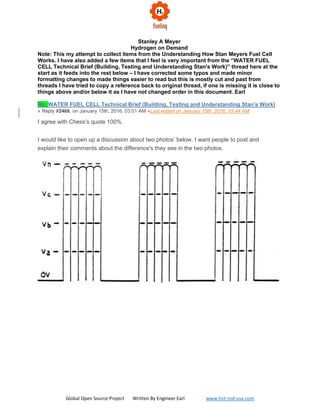
  • 3. Global Open Source Project Written By Engineer Earl www.hot-rod-usa.com like what you said about the people here at RWG over at Ionization forum. Maybe it was just about me who knows. Just to show I can knock chips off my shoulders I'm even going to help you here. Pic 1 Re: WATER FUEL CELL Technical Brief (Building, Testing and Understanding Stan's Work) « Reply #2474, on January 15th, 2016, 05:52 PM »Last edited on January 16th, 2016, 01:27 PM In the Pict.2 you will see a constant high voltage, from 0v to Va. You never want the voltage to fall below this voltage because it sets up the polarization process and low gas production and it can never be lost. As you can see this is a constant pulse voltage with no gating at all. You can see this in Pict.3
  • 4. Global Open Source Project Written By Engineer Earl www.hot-rod-usa.com Pic 2 Pic 3
  • 5. Global Open Source Project Written By Engineer Earl www.hot-rod-usa.com Bsse Knowledge how_the_stan_meyer_tech_works 2 July 2018 (1).pdf Pic 3 (Notice the dashes are one part and dashes/hump are the second part Earl) Re: WATER FUEL CELL Technical Brief (Building, Testing and Understanding Stan's Work) « Reply #2476, on January 15th, 2016, 06:00 PM »Last edited on January 16th, 2016, 01:29 PM Now let's increase the voltage from Va to Vn. Pic 3 Re: WATER FUEL CELL Technical Brief (Building, Testing and Understanding Stan's Work) « Reply #2477, on January 15th, 2016, 06:02 PM »Last edited on January 15th, 2016, 06:08 PM There you go the gating shows up in full view. The old saying goes, it takes money to make money. Same goes For Stan's way, it takes gas to make gas.
  • 6. Global Open Source Project Written By Engineer Earl www.hot-rod-usa.com Re: WATER FUEL CELL Technical Brief (Building, Testing and Understanding Stan's Work) « Reply #2478, on January 15th, 2016, 06:12 PM » Interesting info GPS, thanks for sharing. So are you saying the voltage shouldn't be completely shut off during gating? Re: WATER FUEL CELL Technical Brief (Building, Testing and Understanding Stan's Work) « Reply #2479, on January 15th, 2016, 06:16 PM »Last edited on January 15th, 2016, 07:09 PM Exactly, if you shut the voltage off completely you will never create the polarization process and keep it going. The polarization process can't be created on the fly like in Pict1 using high voltage. Re: WATER FUEL CELL Technical Brief (Building, Testing and Understanding Stan's Work) « Reply #2482, on January 15th, 2016, 06:28 PM »Last edited on January 15th, 2016, 06:34 PM GPS, How do you keep the circuit from not shutting off during gating? From the looks of Stan's circuits it seems like they shut off completely during gating. The only thing I can think of is maybe the gate frequency has something to do with it? Re: WATER FUEL CELL Technical Brief (Building, Testing and Understanding Stan's Work) « Reply #2483, on January 15th, 2016, 06:32 PM »Last edited on January 16th, 2016, 01:33 PM I had to build a circuit to do it. But with Stan's GMS and VIC cards it will do it all for you. But I will tell you the gating frequency and the pulse frequency has to synchronized with each other. Stan does this with his frequency card. All the frequencies that come from his main frequency card is all synchronized with each other. Just build yourself Stan's frequency card and build yourself an offset circuit for the gating frequency. Re: WATER FUEL CELL Technical Brief (Building, Testing and Understanding Stan's Work) « Reply #2484, on January 15th, 2016, 06:36 PM »Last edited on January 15th, 2016, 06:49 PM by gpssonar Quote from gpssonar on January 15th, 2016, 06:32 PM I had to build a circuit to do it. But with Stan's GMS and VIC cards it will do it all for you. But I will tell you the gating frequency and the pulse frequency has to synchronized with each other. Stan does this with his frequency card. All frequency that come from his frequency card is all synchronized with each other.
  • 7. Global Open Source Project Written By Engineer Earl www.hot-rod-usa.com Just build yourself Stan's frequency card and build yourself an offset circuit for the gating frequency. That doesn't make sense to me, unless there is something I am not seeing in his diagrams and PCB's. Which frequency card are you talking about, the gated pulse freq gen or the variable pulse freq gen? Re: WATER FUEL CELL Technical Brief (Building, Testing and Understanding Stan's Work) « Reply #2485, on January 15th, 2016, 06:39 PM » The main frequency generator board. Re: WATER FUEL CELL Technical Brief (Building, Testing and Understanding Stan's Work) « Reply #2486, on January 15th, 2016, 06:42 PM » The gate board is for the GMS unit that controls the gating for the Digital control means card. Re: WATER FUEL CELL Technical Brief (Building, Testing and Understanding Stan's Work) « Reply #2487, on January 15th, 2016, 06:46 PM »Last edited on January 15th, 2016, 06:49 PM you could do that adding a second primary OR varying the voltage don’t you? I just cannot see those wires going anywhere. I think that’s only half the answer =) isn’t it? Re: WATER FUEL CELL Technical Brief (Building, Testing and Understanding Stan's Work) « Reply #2488, on January 15th, 2016, 06:51 PM »Last edited on January 15th, 2016, 06:56 PM what is an off set circuit for the gating ? I imagine the gating doing the reverse...kind of raising the voltage for the production when needed on demand? Re: WATER FUEL CELL Technical Brief (Building, Testing and Understanding Stan's Work) « Reply #2489, on January 15th, 2016, 06:55 PM »Last edited on January 16th, 2016, 01:34 PM
  • 8. Global Open Source Project Written By Engineer Earl www.hot-rod-usa.com All you will need is an offset circuit for the gating frequency. You can find one in Stan's circuits. There is one on the voltage control card and also on the Vic card. I'm sure you can find a simple offset circuit on the web. R.Walke Re: WATER FUEL CELL Technical Brief (Building, Testing and Understanding Stan's Work) « Reply #2490, on January 15th, 2016, 06:57 PM » Beautiful explanation Ronnie. I can't believe we all missed that. Re: WATER FUEL CELL Technical Brief (Building, Testing and Understanding Stan's Work) « Reply #2491, on January 15th, 2016, 07:01 PM »Last edited on January 15th, 2016, 07:12 PM It's just an offset that raises the gate signal above 0 volts to 2, 3, 4, 5 volts above ground state, so the polarization once created can't be lost. When Stan say's the process starts all over again, He don't mean from ground state. Re: WATER FUEL CELL Technical Brief (Building, Testing and Understanding Stan's Work) « Reply #2492, on January 15th, 2016, 07:13 PM »Last edited on January 15th, 2016, 07:20 PM Can you point it out in Stan's circuits....That's something I've never noticed before. From what I just looked at it's part of the 741 op amps Stan used? Re: WATER FUEL CELL Technical Brief (Building, Testing and Understanding Stan's Work) « Reply #2493, on January 15th, 2016, 07:30 PM »Last edited on January 15th, 2016, 07:39 PM It is part of the 741 op amps. This is just one example of offset and gain control. If you look at the GMS and Vic unit all the offsets and gains has lock nuts on them so they can be set and never be moved once set. If you look at the Accel card on the GMS unit you will see low idle and Max that is also offset and gain controls.
  • 9. Global Open Source Project Written By Engineer Earl www.hot-rod-usa.com Re: WATER FUEL CELL Technical Brief (Building, Testing and Understanding Stan's Work) « Reply #2494, on January 15th, 2016, 07:44 PM » Wow, that alone is probably what has stopped so many of us from getting the cell working. Thanks GPS The only issue it's going to cause is if you don't have it right, you'll saturate the core. Re: WATER FUEL CELL Technical Brief (Building, Testing and Understanding Stan's Work) « Reply #2495, on January 15th, 2016, 07:48 PM » You won’t saturate the core if you pick the right core for the frequency you will be pulsing at. Re: WATER FUEL CELL Technical Brief (Building, Testing and Understanding Stan's Work) « Reply #2496, on January 15th, 2016, 07:51 PM »Last edited on January 15th, 2016, 08:06 PM Here is a couple things that may help you understand better also. PolarizationProcess. Pic Pic 3 Re: WATER FUEL CELL Technical Brief (Building, Testing and Understanding Stan's Work) « Reply #2497, on January 15th, 2016, 07:54 PM »Last edited on January 15th, 2016, 07:58 PM Quote from HMS-776 on January 15th, 2016, 07:44 PM
  • 10. Global Open Source Project Written By Engineer Earl www.hot-rod-usa.com Wow, that alone is probably what has stopped so many of us from getting the cell working. Thanks GPS I know that is the reason people has not got gas out of their cells. But there is more once you get the polarization started. We will get to it all as time goes by. That should be enough to keep people busy for a while including Ed M. Stop throwing high voltage to the cell Ed, it won’t do you any good believe me. I done been there. Re: WATER FUEL CELL Technical Brief (Building, Testing and Understanding Stan's Work) « Reply #2498, on January 15th, 2016, 08:07 PM » It does make sense as it keeps the molecules aligned during the "off time". I looked into dielectric relaxation years ago but never connected the dots... Re: WATER FUEL CELL Technical Brief (Building, Testing and Understanding Stan's Work) « Reply #2499, on January 15th, 2016, 08:18 PM »Last edited on January 16th, 2016, 01:37 PM Exactly, as long as them little molecule's buggers are spinning you will never stop them long enough to align them to make any gas using Pic1. By the time you get them to slow down your letting them spin again. :) Re: WATER FUEL CELL Technical Brief (Building, Testing and Understanding Stan's Work) « Reply #2501, on January 15th, 2016, 09:55 PM »Last edited on January 15th, 2016, 09:58 PM Ronnie, Your last string of posts have made it absolutely clear to me why you chose to use Stan's exact circuits. There was no way you could have known what to do until you actually saw Stan's circuits doing it. Thank God you listened to your gut on this one. Also, great detective work reverse engineering Stan's circuits. I know others have tried. I think Nate made good progress, but it would have taken quite a bit more time hadn't you come along. Re: WATER FUEL CELL Technical Brief (Building, Testing and Understanding Stan's Work) « Reply #2505, on January 15th, 2016, 11:42 PM »Last edited on January 21st, 2016, 03:09 PM Looking at the Voltage Amplitude Control, is producing 2V to 9V feeding the tx of the primary. The offset and gain, control the 2V offset and gain the speed it will adjust the voltage depending on the input (J) pulse frequency from the accelerator card. ~webmug Re: WATER FUEL CELL Technical Brief (Building, Testing and Understanding Stan's Work) « Reply #2506, on January 16th, 2016, 05:03 AM »Last edited on December 16th, 2016, 03:41 PM by haxar
  • 11. Global Open Source Project Written By Engineer Earl www.hot-rod-usa.com Awesome teaching Ronnie!!I we were to build the opamp schematic what signal do we need to feed on J'' conection without building the digital control means, analog voltage gen. because they are tied together. And Ronnie is right once again about the freq of the gate. The variable freq gen sets up the freq of the whole gated signal but works only on two settings if you go up in freq the 74122 is not reacting. Offsett pic
  • 12. Global Open Source Project Written By Engineer Earl www.hot-rod-usa.com Complete_Circuit_with_values_3-18-2012.png
  • 13. Global Open Source Project Written By Engineer Earl www.hot-rod-usa.com Pic Re: WATER FUEL CELL Technical Brief (Building, Testing and Understanding Stan's Work) « Reply #2507, on January 16th, 2016, 07:37 AM » Thanks, Ronnie, for sharing / teaching us that important bit of information. There is value in knowing something works, but the greater value is in knowing why that something works. Re: WATER FUEL CELL Technical Brief (Building, Testing and Understanding Stan's Work) « Reply #2510, on January 16th, 2016, 01:54 PM »Last edited on January 16th, 2016, 02:09 PM Quote from Matt Watts on January 15th, 2016, 09:55 PM Ronnie, Your last string of posts have made it absolutely clear to me why you chose to use Stan's exact circuits. There was no way you could have known what to do until you actually saw Stan's circuits doing it. Thank God you listened to your gut on this one. Also, great detective work reverse engineering Stan's circuits. I know others have tried. I think Nate made good progress, but it would have taken quite a bit more time hadn't you come along. Matt, All I knew is I got it to working again, But I was not going to post anything about how it works until I was able to confirm it with Stan's electronics. Building all this is making it all come together and putting a lot of theories to rest. I can't wait to get into the choke and cell and how the cell is charged up. But right now, people have enough to chew on for a while with the polarization process. Re: WATER FUEL CELL Technical Brief (Building, Testing and Understanding Stan's Work) « Reply #2518, on January 16th, 2016, 09:08 PM » Awesome to hear that story. Thanks for sharing it! I'll set up a camera once I start testing again. I have a good feeling about it all this time thanks to your and Adams help. Just got my new scope today, awaiting my new dual channel freq gen and some other equipment....Hopefully testing will start again in a month or less. Re: WATER FUEL CELL Technical Brief (Building, Testing and Understanding Stan's Work) « Reply #2519, on January 16th, 2016, 09:12 PM »Last edited on January 16th, 2016, 09:17 PM Does your dual frequency counter have offset control on it? Also check it and see if both frequencies are synchronized with each other. Re: WATER FUEL CELL Technical Brief (Building, Testing and Understanding Stan's Work) « Reply #2523, on January 17th, 2016, 04:50 PM »Last edited on January 17th, 2016, 05:07 PM
  • 14. Global Open Source Project Written By Engineer Earl www.hot-rod-usa.com Some people has looked at my sperm wave and made comments about it. For some reason they must have not read the first few pages of the Tech Brief where it states. Modulation Pic Wave Pic Re: WATER FUEL CELL Technical Brief (Building, Testing and Understanding Stan's Work) « Reply #2524, on January 17th, 2016, 06:24 PM »Last edited on January 17th, 2016, 07:12 PM So, it's an amplitude modulated wave??? The resonant freq is the carrier while the gate is the modulating wave? Stan led us all to believe he was charging the capacitor to a high DC voltage? I still don't get Stan explaining the choke as a pfn, it discharges right when the applied pulse ends. I guess you could call it a pfn but an inductor does the same thing.... Re: WATER FUEL CELL Technical Brief (Building, Testing and Understanding Stan's Work) « Reply #2526, on January 18th, 2016, 05:02 AM » Quote from gpssonar on January 17th, 2016, 04:50 PM Some people has looked at my sperm wave and made comments about it. For some reason they must have not read the first few pages of the Tech Brief where it states.
  • 15. Global Open Source Project Written By Engineer Earl www.hot-rod-usa.com Perhaps this might help? http://www.angelfire.com/moon2/xpascal/MoonHoax/ApolloSystems/ApolloSystems.HTM Re: WATER FUEL CELL Technical Brief (Building, Testing and Understanding Stan's Work) « Reply #2528, on January 18th, 2016, 08:32 AM »Last edited on January 18th, 2016, 08:39 AM Timeshell, Great find, tons of similarities there. GPS, Stan's waveforms are taking me back to Puharich's work, surely they were doing the same thing, their circuits are nearly identical. Maybe all of Stan's talk of charging the capacitor to a high DC voltage was another method he used to keep people from replicating his work and to keep the patent office from realizing he was doing the same thing as Puharich? BTW, when I modeled and simulated the VIC in multisim a few years back I added in the capacitance of the chokes. Once I did this, I simulated the circuit and guess what happened? I got an Amplitude Modulating waveform! Maybe that is why Stan talks about the coil capacitance as if it's so important. In that circuit the resonance was occurring between the choke and the cell, but the chokes themselves also formed a parallel LC circuit which caused the voltage across the cell to change polarity, even with the diode in the circuit the choke capacitance makes it possible. Re: WATER FUEL CELL Technical Brief (Building, Testing and Understanding Stan's Work) « Reply #2532, on January 22nd, 2016, 07:57 AM »Last edited on January 22nd, 2016, 08:01 AM @Ronnie, Can you tell a bit more on what point (M, M1, J, A) in the circuits the yellow and blue (duty-cycle) scope traces are measured showing in your video? I think I know, but I'm not sure... yellow is (to primary coil TX1) and blue (M, M1)? Re: WATER FUEL CELL Technical Brief (Building, Testing and Understanding Stan's Work) « Reply #2533, on January 22nd, 2016, 04:18 PM »Last edited on January 23rd, 2016, 01:14 PM Sure, there is one (J) output from the analog voltage generator that is connected to the digital control means card. That is the signal that you see going up and down. They are several outputs of the J signals that comes out the Digital control Means board. One (J) goes to the voltage amplitude for the primary. Some of the J outputs goes to other cards. The (M) on the digital control means card is the signal that is fed into the analog voltage generator which
  • 16. Global Open Source Project Written By Engineer Earl www.hot-rod-usa.com produces the J signal. (M1 through M4) goes to the injector cards which is the signal that you see going back and forth which controls the injection (on) time and other things. Re: WATER FUEL CELL Technical Brief (Building, Testing and Understanding Stan's Work) « Reply #2538, on January 22nd, 2016, 11:52 PM »Last edited on January 22nd, 2016, 11:53 PM Ronnie, I only found one J output connected to the input of the voltage amplitude control, but several M? What do you mean with several J outputs?? ~webmug Re: WATER FUEL CELL Technical Brief (Building, Testing and Understanding Stan's Work) « Reply #2540, on January 23rd, 2016, 01:20 PM » If you look at Stan's actual Digital control means card you will see it has, I think 4 or 5 (J) outputs on it, that goes out to different circuits. Re: WATER FUEL CELL Technical Brief (Building, Testing and Understanding Stan's Work) « Reply #2541, on January 24th, 2016, 08:15 AM » Quote from Webmug on January 23rd, 2016, 12:07 AM The yellow scope signal. ~webmug the yellow scope signal comes from the analog voltage generator, which is tied to digital control means, meaning build everything just for a simple offset. Anyway, I managed to ''foul'' the J input by building a voltage divider coming in the J input, without that the ''gain pot'' is locked. Don’t know why but the offset pot is adjusting the voltage from 2v to 11.45v, and the gain pot is adjusting the same voltage but in a short range of 2v. How your circuit works Ronnie? which pot does what? Re: WATER FUEL CELL Technical Brief (Building, Testing and Understanding Stan's Work) « Reply #2543, on January 24th, 2016, 05:10 PM »Last edited on January 24th, 2016, 05:17 PM The digital control means board has nothing to do with (J) it only has 5 additional outputs on it from the analog generator board. The analog board sets on top of the digital board. In other words, one J output from the analog board, and that one output is fed to 5 pins on the digital board as outputs. Like the photo below.
  • 17. Global Open Source Project Written By Engineer Earl www.hot-rod-usa.com Re: WATER FUEL CELL Technical Brief (Building, Testing and Understanding Stan's Work) « Reply #2548, on January 25th, 2016, 11:13 AM »Last edited on January 25th, 2016, 11:39 AM Ronnie, I made a group of pics so we can see better. The digital control (has acceleration circuit on it) is tied to the analog voltage gen, then that goes to amplitude control, so...they all tied. I searched all the opamp circuits, I built stan's sch. but it only controls the ON pulse up and down. You cannot control 2 freq with a single output of an opamp. The signal must be fed to the opamp inputs + - to control its offset HMS-776, in pin 2 of the opamp there is not a square wave, but I think you place that to experiment. If we trace back the schematic, we can see that on analog voltage gen there is another offset opamp, and before that there is a manual speed calibration which is a pot as a voltage divider, that’s where the signal starts, excluding the digital control. And from what I saw in all schematics ''VDD'' is 5v, VCC is12v. Re: WATER FUEL CELL Technical Brief (Building, Testing and Understanding Stan's Work) « Reply #2549, on January 25th, 2016, 12:44 PM »Last edited on January 25th, 2016, 09:05 PM Yeah that frequency to the 741 pin 2 represents the gate frequency. You see in the waveform when the gate is "off" the voltage across the resistor (primary coil) decreases but does not go to
  • 18. Global Open Source Project Written By Engineer Earl www.hot-rod-usa.com zero. The amount of offset changes when you adjust the pot. From GPS's explanation that's what I understand the circuit is supposed to do and the simulation shows the same thing....I just picked out all the other stuff as I am not building the whole GMS unit, I just want to get my cell working....I think I need to do more work on the offset circuit though as right now it's just not giving me a wide range of control. Comment added by Earl: Notice in the circuit above M and M1 are the same output. M goes through the Analog voltage path and gets the voltage offset added and it appear from this discussing the gate as well. This is analog part of signal to VIC. M1 goes through the Gated Pulse Frequency Generator which sets the pulse width of the digital signal and passes it to VIC. Re: WATER FUEL CELL Technical Brief (Building, Testing and Understanding Stan's Work) « Reply #2550, on January 25th, 2016, 09:43 PM » Yes, HMS that’s what I said too, the gating must be fed on the opamp input pins. But I did not see on estate photos any connection on the opamps input pins Re: WATER FUEL CELL Technical Brief (Building, Testing and Understanding Stan's Work) « Reply #2551, on January 25th, 2016, 10:41 PM » Pretty sure it's there....anyways that offset circuit I posted came directly from Stan's drawings. Like I said I just removed it from the rest of the GMS so it can be used on its own. Now my question for Ronnie is about the gate and resonant frequency being synchronized? I'm not sure what he means but I think they need to be sync'd so that when the gate turns the circuit on the resonant frequency comes on at the same time and both pulses rising edge lines up. He said there is a sync function in Stan's circuits that do the job, maybe I can take that out and get it to work separately too. Either way I'll be breadboarding some stuff soon, Hopefully I'll have my offset circuit, drive circuit, and sync circuit up and running soon as everything else is ready. Re: WATER FUEL CELL Technical Brief (Building, Testing and Understanding Stan's Work) « Reply #2552, on January 26th, 2016, 02:45 AM »Last edited on January 26th, 2016, 03:00 AM If you look at Stan's schematics, on the digital control means schematic and the analog generator you will see rising edges and falling edges signals with Dots on them. The dots tells you if the signal is on the rise or on the fall edge. In the photo below tells you it cares less what the rising edges is doing or when it occurs, it only cares when the falling edge occurs. That's how he is able to keep everything synchronized, some IC chips works on rising edges and some work on falling edges.
  • 19. Global Open Source Project Written By Engineer Earl www.hot-rod-usa.com Pic RiseFalledge Re: WATER FUEL CELL Technical Brief (Building, Testing and Understanding Stan's Work) « Reply #2553, on January 26th, 2016, 05:11 AM » So, the falling edges of the pulses are synchronized? Re: WATER FUEL CELL Technical Brief (Building, Testing and Understanding Stan's Work) « Reply #2559, on January 29th, 2016, 07:33 PM » Quote from firepinto on January 29th, 2016, 04:16 PM I'm not so sure about slowing down the scan like that, seems like you would want to get back to lock quickly to keep the car running. I agree. Seems also like you would stress components being out of tune that long, unless during the scanning the input voltage is reduced way down to say two volts, like the way GPS did manually when he was first getting his VIC working. Re: WATER FUEL CELL Technical Brief (Building, Testing and Understanding Stan's Work) « Reply #2560, on January 29th, 2016, 08:55 PM » I agree also, don’t have any idea why they would change things to get it to work. It ought to work just like Stan had it set up. Re: WATER FUEL CELL Technical Brief (Building, Testing and Understanding Stan's Work) « Reply #2642, on September 8th, 2016, 08:38 AM »
  • 20. Global Open Source Project Written By Engineer Earl www.hot-rod-usa.com Ronnie can I just ask you something? A spark plug has about 4000 ohms impedance, but I don't think your VIC has nowhere near that, I've been using capacitive reactance calculators and such trying to work out how you tuned the VIC to the spark plug. How did you match the capacitive and inductive reactance of the VIC to the spark plug and did you also have to narrow the spark gap? Did you use any resistive or capacitive elements in the impedance matching network or was it more to do with frequency? Re: WATER FUEL CELL Technical Brief (Building, Testing and Understanding Stan's Work) « Reply #2643, on September 8th, 2016, 09:02 AM » Frequency Re: WATER FUEL CELL Technical Brief (Building, Testing and Understanding Stan's Work) « Reply #2671, on October 4th, 2016, 05:54 PM » Quote from HHO-Dan on October 4th, 2016, 06:24 AM Impedance Must be a HUGE deal or there would not be a 220 Ohm resistor on the primary. Or suppose the primary was exactly the value you wanted, then there would be no need for the resistor. Quote from HHO-Dan on October 4th, 2016, 06:24 AM This can only be there to match the impedance. The primary impedance must be matched yes, but to what is the question. Before you can answer that, you must ask why. You also need to take into consideration what the impedance is during the pulse, not just when the pulse is off. Re: WATER FUEL CELL Technical Brief (Building, Testing and Understanding Stan's Work) « Reply #2672, on October 5th, 2016, 03:47 AM » Exactly, Matt
  • 21. Global Open Source Project Written By Engineer Earl www.hot-rod-usa.com -------------------------------------------------------------------------------------------------------------------- "Understanding How Stan Meyers Fuel Cell Works" « on October 22nd, 2016, 04:13 AM »Last edited on October 23rd, 2016, 05:58 PM The time has come to tell my story how Stan Meyers Fuel Cell Works. October the 23th 2016 First! I want to have a disclaimer statement. I Ronnie Walker will not be responsible for anyone that uses this information in this thread to create any type of voltage and current either high or low of either of the two. You take full responsibility of your own actions and the use of any information that is discussed in this thread. "High Voltage and Current can KILL You" This thread, and the post in this thread made by me or others, is for information use only. Second! It is assumed that anyone that uses this information has at least the basic knowledge of electronics, formulas and equations. Therefor I will not be held responsible for anyone that uses this information and cannot get a Fuel Cell to work. In other words DON'T BLAME ME! Thanks, Ronnie Walker (gpssonar) Let's get started! (October 23, 2016) Several years back I made the discovery how Stan was able to produce gas on demand for the second time. Like everyone else I keep throwing voltage to the water hoping to see it just fall apart into Hydrogen and Oxygen with no luck at all. Like everyone else, with very little production of the two gases. (Due to Amp Leakage) I came across a drawing in Stan's Tech Brief that clearly shows that there is amp leakage in the cell. (Which I will Post below) Like everyone else, I thought the resonant reaction Stan talked about, was on the water itself. When in fact the resonate action will only take place when the water is removed from within the cells. Then an only then will the two choke coils come together and interact with one another. As long as there is water between the cells, the two choke coils will not interact with each other which will stop any resonance to occur between the two due to the dead short. (Water) Stan states, that you must overcome the dead short condition before resonance will occur and allow the voltage to take over and do the work. This is where everyone including me took this statement way out of context.
  • 22. Global Open Source Project Written By Engineer Earl www.hot-rod-usa.com It does not mean applying a high voltage to the water and it will just go away. It means removing the water within the cells, which is a dead short condition in order to overcome it. So the question is how do we remove the dead short condition so the coils can interact with one another? The answer is Amp leakage within the cell. So how do we create this Amp leakage in the cell? The answer is with the L1 Choke Inductive Reactance and the Cell Capacitance Reactance. When you design the choke and the cell it has to meet certain criteria. When you subtract the two from one another you don't want the math to come out to zero. What you want is an ohm value left over. That ohm value is what is going to cause the Amp leakage within the cell. This is where you get into voltage leading the current or voltage lagging the current, depending on if the net value of ohms is capacitive or inductive. So in other words as the voltage increases so does the amp leakage. At a certain point of increased voltage, the water will be removed from the cell and will be replace with gas. This is where the resonate reaction will occur between the two chokes and the voltage will take off to infinity and the amps will drop to nearly nothing. (Voltage taking over and doing the work). Since all coils are adding one another. In the drawing I have colored it showing the water in blue and gas in yellow. As you can see there is amp leakage that causes the water to be removed and replaced with gas or gasses. Once this is achieved and only when this is achieved is when you will see a resonate condition take place to make Stan Meyers Water Fuel Gas on Demand.
  • 23. Global Open Source Project Written By Engineer Earl www.hot-rod-usa.com Re: "Understanding How Stan Meyers Fuel Cell Works" « Reply #3, on October 23rd, 2016, 01:01 PM »Last edited on October 23rd, 2016, 01:19 PM As you can see, we don't want resonance to occur until the water is removed. In fact, we are using the water itself to prevent it from occurring until the water is removed at the same time as the maximum applied voltage is reached. Re: "Understanding How Stan Meyers Fuel Cell Works" « Reply #6, on October 23rd, 2016, 01:26 PM »Last edited on October 23rd, 2016, 01:36 PM Quote from X-Blade on October 23rd, 2016, 01:18 PM Ronnie, and what happens in relationship to L2 before the Water being "removed"?
  • 24. Global Open Source Project Written By Engineer Earl www.hot-rod-usa.com The resistance in the coil of wire on the L2 choke is used as to restrict amps as well. It will not become part of aiding the voltage until resonance occurs. Only when the water is removed will the two chokes interact with one another. As Stan states the water is part of the circuit, but once the water is removed you are left with the resistance of the wire used in the coils. The water itself and the amount of amp leakage gives you control to reach maximum voltage before resonance occurs. Re: "Understanding How Stan Meyers Fuel Cell Works" « Reply #8, on October 23rd, 2016, 01:38 PM »Last edited on October 23rd, 2016, 02:02 PM Quote from X-Blade on October 23rd, 2016, 01:35 PM So, the coil behaves only resistive at this time? Or reactive to? The L1 coke is inductive and the l2 is resistive until the water is removed then it becomes inductive and aids to the voltage when resonance occurs. People talks about frequency doubling the wrong way. Frequency doubling will not and does not occur until the water is removed and resonance takes place. Also step charging is taking out of context also. Step charging only occurs as the water is being removed. Once the water is removed and resonance takes place you won’t see step charging anymore. It's not something you will see that still stays on your scope. All you will see on the scope is the two chokes interacting with one another and their resonate reaction with one another once resonance is achieved. You have to start the process over again in order to see step charging take place again, or lower and raise the voltage. Re: "Understanding How Stan Meyers Fuel Cell Works" « Reply #10, on October 23rd, 2016, 02:13 PM » So, we are still after resonance, but only when the cell is empty of water. In this condition, if things are tuned properly, we should be able to waive a fluorescent bulb near the cell and see the glow from the high voltage. I would call that basically step one to ensure the VIC is actually working as it should. One might want to connect a high voltage oscilloscope probe and verify, but really all that is needed is something to indicate there is a couple thousand volts per water cap (individual cell). Step two, that you just went into is intentionally creating amp leakage, otherwise known as brute force electrolysis. We need this to electrically separate the plates--make them
  • 25. Global Open Source Project Written By Engineer Earl www.hot-rod-usa.com a true capacitor by removing the dead short. This is where all the bunk about coating the plates goes out the window. The raw stainless is fine once we have gas between them and not all water. And once we have gas, the voltage in there will prevent water from returning. The voltage will jump and stay that way under the resonant conditions. So, here's my question about step two: Is the amp leakage needed in proportion to the cell and/or plates? Meaning, if the plates are large, more amp leakage is needed to create sufficient gas where the voltage can begin to rise. But... There is a limit, if we attempt to draw too many amps from those small gauge wires, it's game over. So, the VIC dictates the dimensions of the cell. It would also seem the cell could be too small allowing the voltage in the VIC to climb too high, also another disaster when the wires begin to arc over. So, if you would Ronnie, can you confirm to us that there needs to be a pretty decent match between the cell and the VIC--get outside the boundaries and the VIC smokes. Or... Is the voltage produced by the VIC limited to the Q-factor of the resonant components--coils and water cap? Re: "Understanding How Stan Meyers Fuel Cell Works" « Reply #11, on October 23rd, 2016, 02:14 PM » People has made the statement many times, There is no way Stan could be producing enough gas to run an engine. The Fact is Stan doesn't have to produce a lot of gas to run a car or air plane, or rocket engine. It's not done by producing a lot of gas. It is done by exciting the gas to a higher voltage to make what gas he does make more powerful. That's why it has to be diluted to equal the burn rate of gasoline or any other fuel source that is being used. Re: "Understanding How Stan Meyers Fuel Cell Works" « Reply #13, on October 23rd, 2016, 02:32 PM »Last edited on October 23rd, 2016, 02:50 PM Let me try and answer one question at a time. Amp leakage needed is not due to surface area or the length of cells, it is due to the gap of the cell and the amount of water that needs to be removed and the voltage you are trying to achieve. You want the water to be removed at the same rate as voltage applied. in other words, you don't want the water removed at 6 volts and resonance to occur when your wanting to apply 12 volts to the primary. The higher voltage you can apply to the gas the more excited it will be and will become a more powerful gas. It is something you have to control with math when designing the VIC and cell. The smaller the water gap, therefore it takes less amp leakage due to less water to be removed. As you see this in the water injector. You are exactly right Matt, you cannot draw more current than the wire you use will allow. This is where everyone needs to be careful, once resonance occurs the voltage
  • 26. Global Open Source Project Written By Engineer Earl www.hot-rod-usa.com will climb towards infinity even with the smallest amount of current in the secondary side, if knocked out of tune it will make toast out of your VIC in an instant. Unlike those, that allows people to set and turn knobs, you cannot allow anyone to tune anything once resonance is achieved. And to answer your question about match between the Vic and Cell, yes it has to be a matched by design, you want all cells to have close to a perfect match as you can get. That way you have the same voltage across each cell, which will require the same Amp leakage to remove the water at the same time. You want the resonance to occur at the same time in each cell. Re: "Understanding How Stan Meyers Fuel Cell Works" « Reply #31, on October 24th, 2016, 02:51 AM »Last edited on October 24th, 2016, 03:10 AM Russ is right, The Vic uses the L1 and the cell to get the system started. That's what I was saying it is by design, The Inductance reactance of L1 and the Capacitance reactance cannot be zero when the math is done or in other words balanced. It has to be a positive number which will be (ohms) when they are subtracted from one another, not reactance of either of the two. This will allow a small amount of current in the cell as the voltage amplitude increases up to 11 or 12 volts. You do not want the water to be flushed from the cell until you reach almost maximum applied voltage. You want it to be flushed with graduations of voltages 2 4 6 8 10 volts. Therefore, you get maximum voltage when the system goes into resonance at around 10 or 11 volts from the VIC's primary. It's so important that the system doesn't try to go into resonance with water still in the cell, all you will get is amp leakage production. It is also important that it doesn't go into resonance with the cells flushed at 6 or 8 volts because you lose all that voltage you still have left (12) volts. You want the resonate action to take place at or close to peak input voltage, that way you get maximum high voltage when the system goes into resonance. Re: "Understanding How Stan Meyers Fuel Cell Works" « Reply #59, on October 24th, 2016, 02:01 PM » Ronnie, having read what you've said about the function of the VIC and tuning of the cell etc., can you explain how those principles fit into the below schematic for Stan's simple bifilar system. You will see that both coils lengths are the same and there is no primary, it is fed with rectified AC voltage in bursts using a gate. The voltage is 0- 115vAC probably using a variac. Can you explain to the forum the phases of the bifilar, each coils relationship to each other and their relationship to the cell and why Stan has written 'Amp inhibiting circuit (without amp influxing)'
  • 27. Global Open Source Project Written By Engineer Earl www.hot-rod-usa.com Re: "Understanding How Stan Meyers Fuel Cell Works" « Reply #66, on October 24th, 2016, 02:25 PM » That's a good photo to share, I was going to share it later, but since you already have, I will talk about it. First: it shows that the chokes does not have to be on the same core material as the primary and secondary. You will find a few more to prove this in the Tech Brief. Second: It shows a balance coil design which leaves you with only one variable left that you can make adjustments with. (which is the capacitors) Which he used tubes that he could slide up and down to make adjustments with along with a flat plate cell that is a variable to tune the system. Third: The l2 choke is always an amp inhibitor until the system hits resonance then and only then will it react with the other coils. Re: "Understanding How Stan Meyers Fuel Cell Works" « Reply #71, on October 24th, 2016, 02:47 PM »
  • 28. Global Open Source Project Written By Engineer Earl www.hot-rod-usa.com I've tested this arrangement many times. It is for all intents and purposes a differential mode choke. It allows frequencies of one nature to pass freely while choking other frequencies. It does so because the Q factor changes from one frequency to another. The flux lines cancel each other out @ self resonance and that is why it inhibits current, when the coils go into self resonance the magnetic lines of flux still cancel each other out in differential mode but the voltage builds up if an escape line of capacitors is not present in which case it dumps the voltage to ground usually. Stan collects the differential mode voltage in his cell instead of dumping it to ground. That is my understanding of it. See here: Re: "Understanding How Stan Meyers Fuel Cell Works" « Reply #72, on October 24th, 2016, 03:03 PM »Last edited on October 24th, 2016, 03:10 PM Quote from X-Blade on October 24th, 2016, 02:30 PM Ronnie, Is that second stage (resonance) automatic when the voltage goes up to a certain level or we have to do something special? We can clearly hear Stan saying that resonance superimposes the particle impact to the polarization process rising the yield of gas production (New Zealand house meeting video) You want that resonance to occur at your peak voltage applied to the primary and not before. That way you get all the high voltage you can produce on the secondary side when it goes into resonance. The leakage current is what's controlled from 2 to 11 or 12 volts. it's automatic once tuned the L1 choke and cells has to be designed to setup the amp leakage along with Frequency. Let's take Stan's primary for instance: It has 10.5 ohms in the coil of wire used because he wants a 500 turn on the primary.
  • 29. Global Open Source Project Written By Engineer Earl www.hot-rod-usa.com The wire he uses is rated at 1.2 amps. in order to get 1.2 amp in the primary you just take 10.5 ohms and a 220 ohm resistor in parallel with the coil and it will give you 1/(1/220+1/10.5)= 9.97 close enough to 10 ohms then you take 12volts/10ohms=1.2 amps You don't want to fool with your turn count ratio. Re: "Understanding How Stan Meyers Fuel Cell Works" « Reply #82, on October 25th, 2016, 02:44 PM »Last edited on October 25th, 2016, 03:04 PM Quote from nav on October 24th, 2016, 04:09 PM Stan used the wiper arm on L2 to regulate the voltage on one set up but on the bifilar set up there is no regulator apart from the plates. That would mean the plates would need to form a plasma ark to create a voltage dump so that the reactance of the cell could be matched. Here is how I think Tesla did it: Anyway, I'm hogging your thread, sorry I'll just be on the sidelines from now on. I want to put to rest what the L2 choke is: I haven't told this to anyone so you’re going to see it here for the first time. It is a built in Phase-Shifter Circuit in the VIC, it’s for the purpose of providing a desired phase shift in the output voltage compared with the input voltage. Depending on the value of the capacitor and the value of the variable resistor or (inductor) you can determine the phase shift you want. Kind of looks like the Frequency doubling Stan talks about, don't it?
  • 30. Global Open Source Project Written By Engineer Earl www.hot-rod-usa.com Re: "Understanding How Stan Meyers Fuel Cell Works" « Reply #84, on October 25th, 2016, 03:05 PM »Last edited on October 25th, 2016, 03:09 PM Quote from gpssonar on October 25th, 2016, 02:44 PM I want to put to rest what the L2 choke is: It is a built in Phase-Shifter Circuit in the VIC, it is for the purpose of providing a desired phase shift in the output voltage compared with the input voltage. Ah Hah! That's what I suspected. Like I've said before, timing is everything. Look at where that red line is. Do you see your voltage required to get electrolysis started? I do. (see figure below) And since it is timing related, you know what that means--changing the running frequency will raise heck with your desired phase shift. So, you have to get the running frequency nailed down before you attempt to adjust the negative choke, or all bets are off. Re: "Understanding How Stan Meyers Fuel Cell Works" « Reply #86, on October 25th, 2016, 03:13 PM »Last edited on October 25th, 2016, 03:25 PM You are exactly right about that Matt!!!!! and at hammer down and if the gas pressure gets too high in the cell the gas management card shut the cell down to a preset voltage
  • 31. Global Open Source Project Written By Engineer Earl www.hot-rod-usa.com but never turning it completely off and once the cell drops to a low pressure per- set value it turns the cell back on again. Re: "Understanding How Stan Meyers Fuel Cell Works"« Reply #91, on October 25th, 2016, 04:07 PM » Merc, you have to be able to control the phase shift it in Stan's system. Re: "Understanding How Stan Meyers Fuel Cell Works" EDITED « Reply #93, on October 25th, 2016, 05:35 PM »Last edited on October 25th, 2016, 10:54 PM Quote from mercury101 on October 25th, 2016, 03:57 PM Hmm. A phase shift. I seem to remember a toroidal coil or transformer also provides phase shift but perhaps too much for the application? Merc, if you don’t know much about the phases and what it does with C and L do read up on it, you will need to know about it, google "Power Factor" and read up on it, also read up on it here find the sections related to L C and Resonance, and Power factor. http://open-source- energy.org/rwg42985/russ/books/Hawkings%20Electrical%20Guide%20Full%20Set%2 0Vol%201-10.zip if you understand phase shift, sorry for extra information, for others who do not know the relationship between voltage and current, do read up on it. Ronnie, I have a simple Question. explain how and why the diode is in there. We know we are trying to make DC not AC Correct? for me the diode dose may have more reason than meets the eye. like here look at where the ground is, this is in only a few diagrams everything else the ground is left off.: Re: "Understanding How Stan Meyers Fuel Cell Works" « Reply #96, on October 25th, 2016, 06:15 PM »
  • 32. Global Open Source Project Written By Engineer Earl www.hot-rod-usa.com Russ, I haven't seen that drawing where did it come from? It goes against everything he has said about an isolated ground. It has to be a mistake or something. I have looked at all his VIC's and none of them are grounded. So, I can't comment on that one, other than he mislabeled it. I would like to draw up something to explain the diode before I comment on it. So, I can put some visual to it. I will work in it and post it. Re: "Understanding How Stan Meyers Fuel Cell Works" « Reply #97, on October 25th, 2016, 07:29 PM »Last edited on October 25th, 2016, 07:40 PM Quote from gpssonar on October 25th, 2016, 04:07 PM Merc, you have to be able to control the phase shift it in Stan's system. Like Matt said timing is everything. And for this circuit, timing is handled by the length of wire. You have an AC signal originating from the secondary, one side heads down the positive choke; the other down the negative choke. Now one might think where these two signals meet at the WFC, you have maximum voltage separation and that's true, at resonance. But you don't have resonance until the water is displaced. What you have is a direct short through the water. In essence the output of both chokes are shorted together at this stage in the operation. That's a no-go all the way around. But we still have this little trick we can play and that is shortening the length of wire on the negative choke. Let's suppose we have a center-tapped secondary and at that center-tap we connect the ground of our two-channel scope as a reference point. Now we connect probe-A to the output of the positive choke and probe-B to the output of the negative choke. What should we see? If the two chokes are equal length, we'll see two identical signals, perfectly in-phase. Make sense? The signal has to travel equal lengths of wire through each choke and therefore they will arrive at the same point at exactly the same time. Now what happens if we shorten the negative choke (take off turns)? You don't suppose we'll see a phase shift, do you? We should. The signal from the negative side of the secondary should get to the output of the negative choke first. So now run a differential between probe-A and probe-B. You should see a voltage there. If that voltage exceeds 2 volts per cell, bingo! You have the start of electrolysis in your WFC. Get to that point and you're off to the races.
  • 33. Global Open Source Project Written By Engineer Earl www.hot-rod-usa.com So now do you see how to tune the negative choke with water in the WFC after you have already tuned for resonance with high voltage on an empty (dry) WFC? The thing to keep in mind with Stan's technique, you are only creating just enough phase shift to squeak out a few volts to start electrolysis; once resonance takes over, these few volts are far overcome by the thousands of volts when the water is fully displaced in the WFC. The little bit of voltage loss due to this phase-shift becomes negligible. Re: "Understanding How Stan Meyers Fuel Cell Works" « Reply #120, on October 27th, 2016, 03:00 PM »Last edited on October 29th, 2016, 02:21 PM Here is a couple photos of the phasing and how the coils are connected. Hope this helps everyone and answers a few questions. Can you tell which coils are aiding and opposing each other?
  • 34. Global Open Source Project Written By Engineer Earl www.hot-rod-usa.com Nav ask the question about the choke coils being the same. The way I can answer this is. As you can see in plain sight in the photos above, there is a B+ and B- voltage. (Example B+ 500 volts and B- 500 volts. (If the choke coils are of equal value)). In a perfect situation, if the L2 choke has the right amount of resistance in it to stop current flow, and because the blocking diode which only conducts electrical energy in one direction. During pulse off time it also would stop current flow back into the secondary to prevent shorting of the secondary. We don't want a perfect situation; we want electron movement in the cell. We want what
  • 35. Global Open Source Project Written By Engineer Earl www.hot-rod-usa.com Stan calls (Electron Bounce), which is electron movement within the cell from plate to plate during On time and Off time. Since voltage is pressure, we can create this electron movement by having two different voltage pressures. (Example B+ 500 volts and B- 450 volts). Re: "Understanding How Stan Meyers Fuel Cell Works" « Reply #124, on October 27th, 2016, 09:32 PM » Quote from Matt Watts on October 27th, 2016, 07:51 PM I can also see the L2 coil appears to have fewer wraps of wire. At least is looks a bit smaller in diameter to me. Primary (Yellow) -> 10.5 ohms Feedback (Green) -> 11.5/11.1 ohms Secondary (Blue) -> 72.4 ohms Choke 1 (Red) -> 76.7 ohms Choke 2 (Red) -> 70.1 ohms AWG 30 resistance to length values: Primary (Yellow) -> 10.5 ohms / (103.2 ohms / 1000 feet) = 101.744186047 feet Feedback (Green) -> 11.5 / (103.2 ohms / 1000 feet) = 111.434108527 feet Secondary (Blue) -> 72.4 ohms / (103.2 ohms / 1000 feet) = 701.550387597 feet Choke 1 (Red) -> 76.7 ohms / (103.2 ohms / 1000 feet) = 743.217054264 feet Choke 2 (Red) -> 70.1 ohms / (103.2 ohms / 1000 feet) = 679.263565891 feet Source: Dynodon's Stan estate data sampling. Continued: http://open-source- energy.org/?topic=119.msg2559#msg2559 Primary to secondary ratio is 1 to 7. Re: "Understanding How Stan Meyers Fuel Cell Works" « Reply #127, on October 28th, 2016, 02:15 AM » Matt, the secondary and L1 are aiding each other and the secondary and L2 are opposing each other. That's how you get a B+ voltage and B- voltage. Compare the two photos below and you can see the aiding and opposing. The second photo came out of the Grobb book if you want to look it up. It's in the chapter 19 Inductance. It will also teach you how to calculate the mutual inductance of aiding and opposing coils. I'm not getting into the Math of it all, right now I just want everyone to be able to Identify all the working parts of the VIC. Re: "Understanding How Stan Meyers Fuel Cell Works" « Reply #130, on October 28th, 2016, 03:11 AM »Last edited on October 28th, 2016, 03:51 AM Quote from ~Russ on October 26th, 2016, 10:13 AM
  • 36. Global Open Source Project Written By Engineer Earl www.hot-rod-usa.com Nav, you remove turns from L2, that is the " wiper arm" it is a thing you tune by removing turns a few at a time ( let’s say 25 at a time) until you see the results your looking for. Matt explained this quite well above. hope this helps. ~Russ Russ if you remember Stan saying in one of his video's he was talking about a tv and how you adjust the B+ voltage. You can do this either by taking turns off the L2 or add turns to L1. But for the Math of everything to keep B+ higher than the B- and to keep it equal and balanced. This goes back to what Nav was talking about when he was stating the coils are matched. Whatever you take off the L2 it must be added back to L1 if that makes any since. That way you only take off half of what you need on L2 and add back to L1. Man, this VIC is a complicated little animal for it to be nothing, but a bunch of wire coiled up on a core. Lol The biggest thing is identifying each part of the VIC and how they work together and knowing how to calculate the math for each part to come up with a working end result when you’re done. You must know what the end result needs to be before you even start. I have described the end result in my posts, so that ought to give some insight of what everyone should be working towards. You want, as in Stan words (Voltage stimulation) (Electron Bounce) (Electron Movement) (Current Flow) whatever the term you want to use along with High Voltage, within the cell but not get back to the Secondary that's the end result. Re: "Understanding How Stan Meyers Fuel Cell Works" « Reply #135, on October 28th, 2016, 09:36 AM » I'm thinking it’s like this Ronnie.
  • 37. Global Open Source Project Written By Engineer Earl www.hot-rod-usa.com So what you're saying Ronnie is that L2 as an opposing current direction to the secondary because both negatives appose each other but because L2 has less turns there is leakage current and voltage and it is the leakage voltage that finds its way to the cell while the vast majority of the current is choked by L2 and secondary cancellation. Brilliant, I should have realized this when I did my bucking coil testing and found leakage voltage. If we hit resonance during pulse off time, the voltage is exponential and not linear, I'm loving this Ronnie. Re: "Understanding How Stan Meyers Fuel Cell Works" « Reply #138, on October 28th, 2016, 02:52 PM » Quote from nav on October 28th, 2016, 09:36 AM I'm thinking its like this Ronnie. You are correct Nav. Thats how it's wired. Re: "Understanding How Stan Meyers Fuel Cell Works" « Reply #144, on October 29th, 2016, 04:59 AM »Last edited on October 29th, 2016, 01:33 PM In this drawing below I have separated the cores for a reason. First, I want you to take notice of the Primary and L2 choke is on the same core coupled together. Next the Secondary and L1 choke is on the same core coupled together. Take notice of the capacitor, it is what brings everything together (other than the magnetic field) that cause
  • 38. Global Open Source Project Written By Engineer Earl www.hot-rod-usa.com the coils to interact with one another. With a dead short this won’t take place, once again you must remove the dead short in the capacitor before any interaction of the coils will occur. You have one transmission line from the secondary and the L2 choke that couples the secondary to the L2 choke. The secondary and L1 choke is already coupled by being on the same core. So therefore, besides the magnetic coupling, it takes the capacitor as well to bring everything together. Re: "Understanding How Stan Meyers Fuel Cell Works" « Reply #146, on October 29th, 2016, 05:32 AM »Last edited on October 29th, 2016, 05:36 AM I think I'm beginning to understand the stages Ronnie. The principle is definitely based on the flyback transformer.
  • 39. Global Open Source Project Written By Engineer Earl www.hot-rod-usa.com
  • 40. Global Open Source Project Written By Engineer Earl www.hot-rod-usa.com This is an important fact Ronnie: When you pulse the primary and are wondering which wires go where, you must make sure in testing that when the primary is pulsed the secondary wire which goes to the diode MUST produce NEGATIVE charge and reverse bias the diode. When the primary is switched off the coils will switch polarity and the wire going to the diode will turn POSITIVE and forward bias the diode Re: "Understanding How Stan Meyers Fuel Cell Works" « Reply #149, on October 29th, 2016, 05:50 AM » Nav, you’re doing a fine job putting things together. Re: "Understanding How Stan Meyers Fuel Cell Works" NEW « Reply #150, on October 29th, 2016, 06:10 AM »
  • 41. Global Open Source Project Written By Engineer Earl www.hot-rod-usa.com http://www.butlerwinding.com/flyback-inductor-transformer/ Great read concerning what happens in Stan's VIC, take note of what is said in the discharging stage statement: The induced current cannot maintain this field but does slow down the decline of the magnetic field. A slower decline translates to a lower induced flyback voltage. If current cannot flow, the magnetic field will decline very rapidly and consequently create a much higher induced voltage. Stan creates opposing negatives and opposes current so that the above statement comes true. The resistor across the primary ensures that the magnetic field collapse across the primary is quick enough for high voltage to be maintained in the secondaries. Look what people are doing when they build flyback transformers for Jacobs ladders and such. They always solder a 220 Ohm resistor across the primary. Here lies the basic principle: If you allow the field to collapse slowly, the induced voltage will be low and the current will be high. If you block the current and collapse the field quickly than the current will be low and the voltage high. TV flyback transformers now have series coils and diodes built in and can produce 30kv output from 12v input @ 300mA. But take note, if they don't spend the voltage at the same rate that it is created then they destroy themselves quickly which is impedance lingo. So, in essence, the VIC is a tv flyback transformer using the reverse voltage bias principle but further blocks the current with L2 opposing the secondary current then uses transmission line impedance matching principles. Also allowing it to operate at the self-resonant frequency of its secondaries which incidentally is also a principle used in more efficient tv flyback transformers. TV's are tuned so that the 30kv from its flyback circuit is always fully used by the tv screen and a dump capacitor. If we build a capacitor and we need to tune it to our flyback circuit, then we too can build a dump to tune it. A big spark gap would be useful. Here is a typical flyback with the tip 3055 and a 240 Ohm resistor, looks remarkably similar to stans primary set up doesn't it? I wonder what the resistance is of a tv flyback secondary? Has Stan just rearranged this schematic?
  • 42. Global Open Source Project Written By Engineer Earl www.hot-rod-usa.com Re: "Understanding How Stan Meyers Fuel Cell Works" « Reply #155, on October 29th, 2016, 09:18 AM » Another flyback drive circuit, this one produces 30kv@ 5 amps but no current restriction. You could fit this drive circuit onto Stan's VIC though and have current restriction @ resonance of the secondary. Ronnie has shown us how to restrict current using L2, this was the stalling point for most, now the gloves are off you can fly. We can take the drive circuits and flyback circuits out of tv's and make this work, you don't have to build stan's circuits. Quote from hydrofuelincanada on October 29th, 2016, 09:42 AM Stan's circuits are needed to make it work the way he intended it to. Safely and automatically.
  • 43. Global Open Source Project Written By Engineer Earl www.hot-rod-usa.com You still can do, but there are other ways like thus which can still be controlled safely. It's understanding the principle at this stage which is important. Superb reading here: http://boginjr.com/electronics/hv/flybacks-guide/ Boy oh boy is this getting good Ronnie. You were right, Stan took his B+ jargon from tv circuitry talk. Quote from gpssonar on October 29th, 2016, 10:25 AM Nav keep up the good work, you are taking a lot of work off my shoulders. Thanks, you don't know how much you are helping. You're welcome. Now we know why Stan placed his tip 3055, voltage regulator and resistors in close proximity to the primary and the pick up coil as in the below picture. I always wondered why the tip 3055 wasn't on the main board and the voltage reg too. It's because they are part of the most common flyback driver circuit ever made and the diode is also part of that famous tv circuit that's been around since the 1940's more or less. Stan has taken this circuit which has a principle of reverse biasing the diode during charging then forward biasing during discharging, he's rebadged it completely and cleverly hidden it from the patent office. In other words, he found out a tv HV driver could charge a cap of his choice as long as he matches the drive circuitry just like a tv drive circuit is tuned to the cathode it drives. Kinda disappointed really in the end that it turned out this way but it's opened up Aladdin’s cave and made things a whole bunch easier. If people can't get the cell working now, then I don't know what to say. Re: "Understanding How Stan Meyers Fuel Cell Works" « Reply #189, on October 29th, 2016, 03:05 PM »Last edited on October 29th, 2016, 03:07 PM
  • 44. Global Open Source Project Written By Engineer Earl www.hot-rod-usa.com Quote from Matt Watts on October 29th, 2016, 03:03 PM So, this one is correct? Yes, sorry about the mistake. I'm trying to do all this out of memory due to not having all my work here. Re: "Understanding How Stan Meyers Fuel Cell Works" « Reply #205, on October 29th, 2016, 03:49 PM »Last edited on October 29th, 2016, 03:57 PM All I can say is, "It takes gas to make Stan's gas". It's a lot easier to take a gas through these stages than it is to try to take water through these stages. Water is only used in the V0 to Vn stage and to keep the process going. It even states Gas Ionization not Water Ionization.
  • 45. Global Open Source Project Written By Engineer Earl www.hot-rod-usa.com Re: "Understanding How Stan Meyers Fuel Cell Works" « Reply #239, on October 30th, 2016, 10:02 AM » Watch this video, then compare it to the drawing with the phasing dots that Stan has on his drawing. https://www.youtube.com/watch?v=LuZh1QnegC4
  • 46. Global Open Source Project Written By Engineer Earl www.hot-rod-usa.com Re: "Understanding How Stan Meyers Fuel Cell Works" « Reply #254, on October 30th, 2016, 04:51 PM »Last edited on October 31st, 2016, 03:36 AM Remember these 3 things about XL and XC. 1. Below the resonant frequency, X L is small, but X C has high values that limit the amount of current. 2. Above the resonant frequency, X C is small, but X L has high values that limit the amount of current. 3. At the resonant frequency, X L equals X C and they cancel to allow maximum current.
  • 47. Global Open Source Project Written By Engineer Earl www.hot-rod-usa.com As Brad stated the total resistance of the coils of wire on the Secondary and L1 and L2 and the Re of the water is what is used to calculate the current. As you can see the less resistance in the coils of wire and Re stays the same can raise the current. But also the resistance of the coils can stay the same and lowering the Re can also raise the current. At resonance when XC = XL all you end up with is the resistance of the coils of wire plus the Re of the Gas that will determine the maximum current at the resonate frequency. Re: "Understanding How Stan Meyers Fuel Cell Works" « Reply #257, on October 30th, 2016, 07:36 PM »Last edited on November 13th, 2016, 02:32 PM Using Stan's Vic and the numbers Don gave us as an example, I will attempt to show how to impedance match it all. Question is what is the purpose of Impedance matching? The answer is Watts in must equal Watts out. (Isn't that right Mr. Watts: clap:) Let's start with the Primary, I have already show it has 10 ohms of impedance in it and how it is calculated. Line(Primary) side=10 ohms 12volts/10ohms=1.2amps 1.2amps*12volts=14.4watts Next we use a transformer (Amplifier) to match the Load side. we need to know the total resistance of the load side.
  • 48. Global Open Source Project Written By Engineer Earl www.hot-rod-usa.com Secondary side= 72.4+76.7+70.1+Re78.54+11.5=310 ohms Now that we have a total resistance of the line side of 10ohms and a total resistance of the load side of 310ohms Next we take the 310ohms and 10ohms and use this formula to get the turn ratio. Ns/Np=sqrt Zs/Zp sqrt (310/10)=5.567 So we need a turn ratio of 5.567 to 1 We know our line voltage is 12volts We can times this by the turn ratio of 5.567 which is =66.816 Load Voltage Now we have our load voltage. Next we calculate the load watts using formula (66.816 ^2)/310ohms= 14.4 watts That's how you do it. :bliss: Matt, The 11.5 is the feedback coil.....and yes that is correct the chokes must match the secondary....That's why if you take turns off the L2 they must be added back to L1. In Stan's example secondary is 73ohms close enough, then 76ohm for the L1 and 70 for L2 if you take 3ohms off the L1 and put that 3 ohms back on the L2 you can see they all match to 73ohms. Why does he do this? It's to get the slight potential difference in voltage needed on the chokes. Yea My brain can't keep all this straight, that's the reason for the spreadsheet. Too much math to deal with all at the same time. Now you can see when someone ask me a question, how my brain gets all scrambled. Re: "Understanding How Stan Meyers Fuel Cell Works" « Reply #263, on October 30th, 2016, 11:16 PM »Last edited on October 30th, 2016, 11:42 PM Quote from gpssonar on October 30th, 2016, 07:36 PM Using Stan's Vic and the numbers Don gave us as and example, I will attempt to show how to impedance match it all. Question is what is the purpose of Impedance matching? The answer is Watts in must equal Watts out. (Isn't that right Mr.Watts :clap:) Hooray! See, I knew I was a part of this whole mess somehow. Quote from gpssonar on October 30th, 2016, 07:36 PM
  • 49. Global Open Source Project Written By Engineer Earl www.hot-rod-usa.com Secondary side= 72.4+76.7+70.1+Re78.54+11.5=310 ohms So secondary coil, plus positive choke, plus negative choke, plus dielectric property of water, plus... What's that 11.5 ohms? Where does it come from? Quote from gpssonar on October 30th, 2016, 07:36 PM That's how you do it. :bliss: Holy cow! The math looks pretty easy, but... I see some interdependency here that will take lots of do and redo to zero in on the final values. I also see how that very fact enables this circuit to function as it does. It has a built-in feedback loop that will constantly attack the water at faster than the speed of light. If anything changes in the cell, the impedance changes immediately, faster than the water can react. This might be the whole key to it Ronnie. Did you ever consider that? The turns ratio will force you to recalculate the resistance of the wire you use to get that many turns, and... The resistance of the wire you spin on the bobbin will force you to recalculate the turns ratio. Hmmm... This could turn out to be a little bit of a pain in the butt. Ronnie, didn't you mention to me a while back that the turns on the chokes need to match the turns on the secondary? So if I was to adjust the secondary, to get the right turns ratio, I would also have to alter the turns on both chokes? That's enough questions for now. I can see why you had a spreadsheet to calculate this stuff. Re: "Understanding How Stan Meyers Fuel Cell Works" « Reply #265, on October 31st, 2016, 03:09 AM »Last edited on October 31st, 2016, 03:56 AM Matt, The 11.5 is the feedback coil.....and yes that is correct the chokes must match the secondary....That's why if you take turns off the L2 they must be added back to L1. In Stan's example secondary is 73ohms close enough, then 76ohm for the L1 and 70 for L2 if you take 3ohms off the L1 and put that 3 ohms back on the L2 you can see they all match to 73ohms. Why does he do this? It's to get the slight potential difference in voltage needed on the chokes. Yea My brain can't keep all this straight, that's the reason for the spreadsheet. To much math to
  • 50. Global Open Source Project Written By Engineer Earl www.hot-rod-usa.com deal with all at the same time. Now you can see when someone ask me a question, how my brain gets all scrambled. Re: "Understanding How Stan Meyers Fuel Cell Works" « Reply #266, on October 31st, 2016, 04:21 AM » Quote from gpssonar on October 30th, 2016, 04:51 PM Remember these 3 things about XL and XC. 1. Below the resonant frequency, X L is small, but X C has high values that limit the amount of current. 2. Above the resonant frequency, X C is small, but X L has high values that limit the amount of current. 3. At the resonant frequency, X L equals X C , and they cancel to allow maximum current. Now this says everything everyone thinks that choke coils restrict current going in cell which is absolutely incorrect Re: "Understanding How Stan Meyers Fuel Cell Works" « Reply #278, on October 31st, 2016, 11:18 AM »Last edited on October 31st, 2016, 11:20 AM by Sulaiman I just realised that I have missed a critical detail, where in the VIC core(s) is/are the airgap(s) Re: "Understanding How Stan Meyers Fuel Cell Works" « Reply #279, on October 31st, 2016, 11:22 AM » Just as I have them here. back to work, talk more later.
  • 51. Global Open Source Project Written By Engineer Earl www.hot-rod-usa.com http://open-source-energy.org/?action=dlattach;topic=2785.0;attach=14138;image Re: "Understanding How Stan Meyers Fuel Cell Works" « Reply #282, on October 31st, 2016, 12:01 PM »Last edited on October 31st, 2016, 12:06 PM Guy's inductors hate reverse current that's why they sound like they are frying when in resonance. What better way to cause oscillation within the cell than to put an inductor on each side of the cell.
  • 52. Global Open Source Project Written By Engineer Earl www.hot-rod-usa.com Sulaiman, I think Ronnie is trying to tell you this:
  • 53. Global Open Source Project Written By Engineer Earl www.hot-rod-usa.com Re: "Understanding How Stan Meyers Fuel Cell Works" « Reply #290, on October 31st, 2016, 02:28 PM » Sulaiman, a few months ago I carefully rejigged the VIC from the estate pictures and found significant gaps in the core as pictured below. You will see where there is a hole in between the bobbins so stan could set the gap in the core. But what is more important is the pickup coil is over the top of one air gap and that is why I thought the middle coil was the primary bridging the gap so I started testing VICs with air gaps with some success but still at a loss to how it works. Ronnie has made it clearer but when Ronnie did his spark plug video, he placed the primary over the air gap but never explained why. Perhaps Ronnie will explain why he did this. I think there is a network on the primary side that somehow bridges the gap and its either the primary or pickup or both together forming a linear core down the primary side of the core then it uses the two chokes and the capacitor to charge the other side of the core. Re: "Understanding How Stan Meyers Fuel Cell Works" « Reply #294, on October 31st, 2016, 04:06 PM » Here is another drawing that may help people with phasing and direction.
  • 54. Global Open Source Project Written By Engineer Earl www.hot-rod-usa.com Re: "Understanding How Stan Meyers Fuel Cell Works" « Reply #295, on October 31st, 2016, 05:28 PM » Quote from gpssonar on October 31st, 2016, 04:06 PM Here is another drawing that may help people with phasing and direction. So, everything is in-phase except the L2. Got it. Re: "Understanding How Stan Meyers Fuel Cell Works" « Reply #316, on November 1st, 2016, 09:59 AM » Ronnie, earlier on in the thread you posted the phases (in blue) all in the same direction with the phase dots running correspondingly. Today you moved the dot on the L2 choke to oppose L1 and the secondary. See pics above. I'm confused, which is correct now? Re: "Understanding How Stan Meyers Fuel Cell Works" « Reply #324, on November 1st, 2016, 11:14 AM »Last edited on November 1st, 2016, 11:19 AM Nav don't take that comment I made personal it was directed to everyone. I just don't get it, I drew up a photo of how the coils are on Stan's Vic and how they are phased and people want scope shots showing it. Damn I can visualize that in my head. I don't need a scope. Again both drawings are the same. The top one of STAN'S is a wire diagram and mine is actually on the Vic as drawn. Stan's drawing is not on the Vic it's a diagram of the Vic circuit.
  • 55. Global Open Source Project Written By Engineer Earl www.hot-rod-usa.com Re: "Understanding How Stan Meyers Fuel Cell Works" « Reply #298, on October 31st, 2016, 07:10 PM »Last edited on October 31st, 2016, 07:17 PM Threw this together to work through the impedance matching. Hopefully it's helpful. The way I did this is to have a manual turns ratio, then a calculated turns ratio using Ronnie's formulas. You can use Excel to goal-seek so that the two values are equal. That will find the values you can build around. Base everything you do off the primary and you should be good to go. Re: "Understanding How Stan Meyers Fuel Cell Works" « Reply #300, on October 31st, 2016, 07:32 PM » Looks great Matt. Re: "Understanding How Stan Meyers Fuel Cell Works" « Reply #300, on October 31st, 2016, 07:32 PM » Looks great Matt. Re: "Understanding How Stan Meyers Fuel Cell Works" « Reply #306, on November 1st, 2016, 03:46 AM » Good questions Gunther, maybe Sulaiman can answer that. The question I have is why exactly is there only one solution to this algorithm? Only one turns ratio that makes this all work as Ronnie detailed?
  • 56. Global Open Source Project Written By Engineer Earl www.hot-rod-usa.com Ris, would you be able to explain this? If no one chimes in on this, I will tonight when I get home from work. Think about this in the meantime. If we didn't know the resistance values of the wire in the chokes and pretend, they didn't even exist and all we knew was what the load impedance is 78.54ohms, where would all the resistance end up to match it to the line impedance? Answer, all on the secondary would it not? I need to go back and reteach this, I see where I got a little ahead of you guy's. Re: "Understanding How Stan Meyers Fuel Cell Works" « Reply #337, on November 1st, 2016, 02:08 PM »Last edited on November 1st, 2016, 02:51 PM Ok let's stop and work the phasing out together, so we all can agree together before me move forward any farther. Going to use actual photo's from the estate photos. Reverse engineering.
  • 57. Global Open Source Project Written By Engineer Earl www.hot-rod-usa.com
  • 58. Global Open Source Project Written By Engineer Earl www.hot-rod-usa.com
  • 59. Global Open Source Project Written By Engineer Earl www.hot-rod-usa.com Nav, Go by Don sketches on the phasing, the photo's I just posted has sitckers on the Vic that Stan put there. S and F sitckers. go by them and follow the wires. You can tell the start of the wires and finish just by looking at the coils on his vic. Re: "Understanding How Stan Meyers Fuel Cell Works" « Reply #369, on November 1st, 2016, 04:32 PM »Last edited on November 1st, 2016, 05:33 PM Let's move on, What I was trying to show in the impedance matching the line to the load was with resistance only. Let's say we only had the line resistance and the load resistance. But we knew the voltage to the line and the amp to the line. We can get the watts from that. We know we need the same watts out of the load. but we only know the load ohms and watts from the line. If we use the same calculation as before. All the resistance would end up on the secondary as one big coil. but still equaling out to 310 ohms when done. Stan needed two chokes on both sides of the capacitors. What better way to do this than to take the secondary and divide it into 3 coils. Take 3.83 ohms from each coil and you have the Feedback coil of 11.5ohms You still end up with the 310 ohms in the load side. But now you have charging chokes to boot. You have the ability to have a LC circuit now. You not only have amp restriction built in because Inductors can't stand reverse current. Now that you have everything impedance matched and inductors in place all you need now is a capacitor to set up the LC circuit. Because at resonance Xl and XC will not have any effect on the impedance match. I hope this helped in identifying all the working parts, and how they were calculated in.
  • 60. Global Open Source Project Written By Engineer Earl www.hot-rod-usa.com Summary: Without inductors, the resistance can be a secondary coil with 73 ohms and a two resistors of 73ohms and a feedback coil of 11.5 ohms and a load of 78.54 ohms. But replacing the two resistors with two inductors will be the same total resistance needed to impedance match the load resistance. Stan's Vic does not have a steel core, it has a ferrite core material and the VIC produces frequencies in the AM range. Re: "Understanding How Stan Meyers Fuel Cell Works" « Reply #378, on November 2nd, 2016, 03:18 AM »Last edited on November 2nd, 2016, 10:55 AM Quote from adys15 on November 1st, 2016, 10:50 PM Ronnie why do you include all the coils as a load and not calculate from the chokes to cell? Because at resonance there is no ohm value if XC and XL is tuned to cancel each other out, So therefore it does not affect the impedance match. The only way you have an ohm value in XC and XL, is if there is a difference left once you subtract the two. We don't live in a perfect world, so therefore our coils are not going to be perfect and our total resistance we need may be a little off here and there as we wind each of the coils, So we can still use the XL and XC to our advantage to still keep all the resistance right by having a small ohm value left once we subtract the two. That is achieved by tuning the frequency. In other words (a little above or below
  • 61. Global Open Source Project Written By Engineer Earl www.hot-rod-usa.com resonate frequency will add an ohm value). That's why when tuning it is so damn touchy, and things can go south real fast. Again that is why you want see anyone touch my cell and turn knobs once tuned and working, (Like I seen another person do), and Stan wouldn't either. Note: If you don't start the tuning around 2 volts on the line and work your way up, You will indeed burn up a coil and not even know it. And you can tune for a year and never get any voltage. The only way you will know if you burn up a coil is to take everything apart and check the inductance of each coils to see which one you fried. Re: "Understanding How Stan Meyers Fuel Cell Works" « Reply #419, on November 4th, 2016, 09:38 AM » Quote from gpssonar on November 4th, 2016, 03:57 AM Question for today: As the dielectric changes in the cell from water to gas, Does the cell capacitance change? Everyone please chime in. Yes, It will, if I set the values for the distance of the plates and the area of the plates and do not change theses.... water has a dielectric constant of 80.10 let’s say we have water the cell, will be n value, let’s say its 7.092054F if we change dielectric constant to 1 ( for let’s say air) we get a capacitance of 0.08854F so indeed the capacitance will change. it will become lower with more gas in the cell, I do not expect it to become the full value of air / H2,O2 mixture. I believe it will be only change some amount, there will still be water paths between the bubbles. between the bubbles, this is where the water will become highly polarized, hence the " bubbles come from the center of the cell, not at the plates" this I have seen. ~Russ Re: "Understanding How Stan Meyers Fuel Cell Works" « Reply #421, on November 4th, 2016, 09:44 AM »
  • 62. Global Open Source Project Written By Engineer Earl www.hot-rod-usa.com Thanks Russ, I'm about to explain something about this, and I needed some people that has done some real testing. Re: "Understanding How Stan Meyers Fuel Cell Works" « Reply #439, on November 4th, 2016, 05:32 PM »Last edited on November 4th, 2016, 05:50 PM Looks like we had a few to chime in on the question of today. Some say's it does, and some say it don't. Some say's it increases and Some say's it decreases and a few say's it stay's the same. This is critical to know. I remember many people saying it was a moving target years ago. When I was doing my research on this, I made a few experiments. 1: Checked the cell's capacitance dry with no water just air. 2: Checked the cells capacitance full of water. 3: Checked the cells capacitance with different levels of water within the cells. For those that think it stays the same, do these three experiments. Once you do these experiments I think you will find the capacitance does indeed change. For those that say's the capacitance does change, Can we all agree we have a variable capacitor? Re: "Understanding How Stan Meyers Fuel Cell Works" « Reply #440, on November 4th, 2016, 05:51 PM » already posted in my excel sheet : as posted here under the Russ 6 single cell mesurments TAB using the cheep meter that seems more correct... with out water: = 16.69pf with water: = 1393pf and if you take 16.69 x 80.1 you get... 1336pf 16.69 x 78 = 1301pf so i can trust that measurement... and everything else in that sheet... individual, series, inside out, ect. series measurements of 6 cells...
  • 63. Global Open Source Project Written By Engineer Earl www.hot-rod-usa.com with out water: 2.20pf with water : 239.8pf lower frequency the higher the capacitance. in my testing... but that meter seems to give measurements that i do not trust... so yes its changes. ~Russ Re: "Understanding How Stan Meyers Fuel Cell Works" « Reply #441, on November 4th, 2016, 05:54 PM »Last edited on November 4th, 2016, 06:00 PM Russ would you call that a variable capacitor if the ratio of gas increases and water decreases, changes the capacitance? Re: "Understanding How Stan Meyers Fuel Cell Works" « Reply #444, on November 4th, 2016, 06:14 PM » Quote from ~Russ on November 4th, 2016, 06:03 PM I would call it a variable in our math, aka we need to know theses as even frequency play's a BIG roll on the capacitance. ~Russ Exactly, Now you and others wanted to know how to tune the system. What I am about to say and show is for manual tuning only, with no feedback coil or phase lock loop device. I have stated many times you have to start out at a couple volts and work your way up a couple volts at a time while tuning until you reach full voltage. What I am about to show everyone is how to use a fixed L to tune into a variable C It is all done by frequency.
  • 64. Global Open Source Project Written By Engineer Earl www.hot-rod-usa.com Re: "Understanding How Stan Meyers Fuel Cell Works" « Reply #445, on November 4th, 2016, 06:21 PM » As you can see at different voltage levels at different frequencies with a fixed L as the capacitance changes, we can use a different frequency with a different voltage and still tune into resonance. If you do the inductance reactance and the capacitance reactance at each level you will find it is still at resonance throughout. Not only that you can see how the step charge is formed. (notice the five frequencies and five pulses) Those number of pulses is determined by the water gap. they can be more or less, all depending on the water gap. Re: "Understanding How Stan Meyers Fuel Cell Works" « Reply #446, on November 4th, 2016, 06:33 PM » yes, this is well known, we must match capacitance reactance with inductance reactance = electrical resonance a "simple" concept... electrical resonance basics 101. ~Russ Re: "Understanding How Stan Meyers Fuel Cell Works" « Reply #447, on November 4th, 2016, 06:35 PM »Last edited on November 4th, 2016, 06:39 PM Ok, so if everyone knows this and its basic 101, they why is no one using it? My next question then is why no one has a working cell if they know this and are using it?
  • 65. Global Open Source Project Written By Engineer Earl www.hot-rod-usa.com Re: "Understanding How Stan Meyers Fuel Cell Works" « Reply #448, on November 4th, 2016, 06:39 PM »Last edited on November 4th, 2016, 06:41 PM Can I make a guess as to something here Ronnie? My hunch is the rate of this change you just showed in the chart is controlled by the turns ratio. Yes? No? Maybe so? Re: "Understanding How Stan Meyers Fuel Cell Works" « Reply #449, on November 4th, 2016, 06:40 PM » Yes Re: "Understanding How Stan Meyers Fuel Cell Works" « Reply #452, on November 4th, 2016, 06:55 PM »Last edited on November 4th, 2016, 07:03 PM What I've seen all along is people throwing 12 volts to the primary and trying to tune to resonance. Can you see the problem why you can't do that? Your using all the voltage you have to tune into the first level of resonance and not allowing the capacitance to change. It's just like doing the same thing at 1 volt but you've use up all the voltage before anything changed. You have to take it through the different voltage levels and tune to resonance at each level. At each level an amount of gas will be released changing the capacitance. As you take it through each level more gas will be released until you reach the last level of resonance by that time gas is in the cell and water is removed and voltage will take over and go to infinity and amp drops. Re: "Understanding How Stan Meyers Fuel Cell Works" « Reply #454, on November 4th, 2016, 07:13 PM » It's as simple as this Matt, if you take a dry cell and tune it to resonance where the inductance is fixed and the capacitance is fixed you can throw 12 volts to the primary and tune it to resonance no problem. When you do this do all your probing and measurements and take notes. You should end up with the same measurements give or take with a wet cell once it goes through the resonance levels and voltage levels. Re: "Understanding How Stan Meyers Fuel Cell Works" « Reply #455, on November 4th, 2016, 07:18 PM »Last edited on November 4th, 2016, 07:26 PM The only other thing that is taking place at resonance, the current is at its highest and the two chokes tries to restrict the current between each choke and that causes some oscillation within the cell. Re: "Understanding How Stan Meyers Fuel Cell Works" « Reply #457, on November 4th, 2016, 07:30 PM »Last edited on November 6th, 2016, 04:22 AM Quote from ~Russ on November 4th, 2016, 07:20 PM
  • 66. Global Open Source Project Written By Engineer Earl www.hot-rod-usa.com I have a quick question. You once told me that you can... After the system is tuned... Just flip on 12v and the system will start. However. This kind of goes agents the voltage frequency step tuning process. So your implying that the system will just start of its tuned already. Can you give me your best guess why this is? Thanks. ~Russ The water bath will hold its charge as long as there is gas pressure in the cell. Once the pressure is lost and the gas is released the cell will discharge. That's why Stan's gas management card and pressure sensor will never let the cell drop below a certain pressure. If you remember also, I said no one would stick their finger in my cell without getting the piss knocked out of them, even with it off. Because we have increased stable capacity of the cell. Re: "Understanding How Stan Meyers Fuel Cell Works" « Reply #458, on November 4th, 2016, 07:38 PM »Last edited on November 4th, 2016, 07:41 PM Another thing I might add, If your using a plastic see through cover for the water bath, check the capacitance of the cell without touching it and then check it with your hand on it. If it changes the capacitance then never touch the plastic cover when the cell goes into resonance, there may just be enough change in capacitance to burn up the VIC. Stan took extra steps even with a thick Delrin cover for this not happened. Just look at his cell that is inside the red gas tank and also even in the metal tank. Re: "Understanding How Stan Meyers Fuel Cell Works" « Reply #480, on November 6th, 2016, 05:41 AM »Last edited on November 6th, 2016, 06:03 AM To make a long story short, Others have proven me wrong when I Made that statement. It was due to me making a mistake when I was drawing up the cells with three and four cells. I made a new drawing with my mistake in it. So disregard that statement. Re: "Understanding How Stan Meyers Fuel Cell Works" « Reply #486, on November 6th, 2016, 06:59 AM »Last edited on November 6th, 2016, 08:57 AM Dan there is more to it than just a capacitance value. Voltage plays a big role in this. If you look at this photo of Stan's, the first level is the polarization process. You want this
  • 67. Global Open Source Project Written By Engineer Earl www.hot-rod-usa.com process to take place with around 2 volts on the primary. If you tune to resonance at 2 volts and you see no gas being produced at all then you know there is something wrong. By leaving it at resonance at 2 volts, raise the voltage from 2 volts 4,6,8,10,12 somewhere in that voltage range you should see some gas being made. Whatever that voltage is that you see the gas being made let's say 6 volts. That should tell you, the turn ratio is off on the secondary, because you want it to take place at 2 volts to the primary not 6 volts. This is where everything gets tricky to adjust. In order to keep the impedance match, what you have to do is take turns off the chokes and add them to the secondary to increase the voltage. By doing this you change the inductance which will change the resonate frequency. So, it's a balancing act that you’re shooting for. Again, if the polarization process takes place at 6 volts and it's supposed to start at 2 then you've lost 4 volts in the process that you can no longer do anything with. Re: "Understanding How Stan Meyers Fuel Cell Works" « Reply #492, on November 6th, 2016, 10:28 AM » Ye i can do that but before I do, I have another Question: Does people understand the polarization process? Because that is where it all starts. I would like to hear peoples thought on this first. Re: "Understanding How Stan Meyers Fuel Cell Works" « Reply #497, on November 6th, 2016, 11:15 AM »Last edited on November 6th, 2016, 11:30 AM Quote from gpssonar on November 6th, 2016, 10:28 AM YeS Ican do that but before I do, I have another Question: Does people understand the polarization process? Because that is where it all starts. I would like to hear peoples thought on this first.
  • 68. Global Open Source Project Written By Engineer Earl www.hot-rod-usa.com let me give a go, we know the "step charging" is not quite the way Stan means, in your way of thinking it’s not really the cap charging in a short pulse duration. like in the resonance attachment .jpg it’s the voltage it takes to get to resonance in the gas phase. the steps are the tuning process, the "polarization process" this is the first part of aligning the water molecules. orientating them for the next phase. This is voltage controlled. This not the same as brought force electrolysis. brought force electrolysis is a surface phenomenon. the "polarization process" is soothing that happens in between the plates. like in figure 7-4 ~Russ
  • 69. Global Open Source Project Written By Engineer Earl www.hot-rod-usa.com Re: "Understanding How Stan Meyers Fuel Cell Works" « Reply #503, on November 6th, 2016, 12:34 PM »Last edited on November 6th, 2016, 04:31 PM Thanks Ris, very good video. Watch the video Ris posted then read this. As you can see the polarization process is started when a voltage is applied to the capacitor plates. It don't matter if it's brute force or not. When you apply a voltage to a capacitor the water molecule will align since we are using natural polarized water as the dielectric. It's just the nature of a dielectric to polarize in a capacitor. If you took notice in the video it showed once aligned it cancels out charges. As you know the water molecule has two hydrogen and one oxygen so there would be two cancels on the neg plate compared to one cancel on the positive plates. Question again: if
  • 70. Global Open Source Project Written By Engineer Earl www.hot-rod-usa.com the battery is left on, would they be more charge accumulate on the neg side than on the positive side? Re: "Understanding How Stan Meyers Fuel Cell Works" « Reply #509, on November 6th, 2016, 05:15 PM »Last edited on November 6th, 2016, 05:25 PM So by the logic in that video (Good find Ris), if we have a dry cell (K = 1) that measures 10pF, without even taking another measurement, we know immediately when the cell is filled with water (K = 80), the capacitance has just increased to 800pF. That much is pretty easy and it completely defines the working range of our cell. Quote from gpssonar on November 6th, 2016, 12:34 PM As you know the water molecule has two hydrogen and one oxygen so there would be two cancels on the neg plate compared to one cancel on the positive plates. Question again: if the battery is left on, would they be more charge accumulate on the neg side than on the positive side?