Recyling of rare earths: a critical review

The rare-earth elements (REEs) are becoming increasingly important in the transition to a green economy, due to their essential role in permanent magnets, lamp phosphors, catalysts, rechargeable batteries etc. With China presently producing more than 90% of the global REE output and its increasingly tight export quota, the rest of the world is confronted with a REE supply risk. Mining companies are now actively seeking new exploitable REE deposits while some old mines are being reopened. Because of the absence of economical and/or operational primary deposits on their territory, many countries will have to rely on recycling of REEs from pre-consumer scrap, industrial residues and REE-containing End-of-Life products. REE recycling is also recommended in view of the so-called “balance problem”. For instance, primary mining of REE ores for neodymium generates an excess of the more abundant elements, lanthanum and cerium. Therefore, recycling of neodymium can reduce the total amount of REE ores that need to be extracted. Despite a vast, mostly lab-scale research effort on REE recycling, up to 2011 less than 1% of the REEs were actually recycled. This is mainly due to inefficient collection, technological problems and, especially, a lack of incentives. A drastic improvement in the recycling of REEs is, therefore, an absolute necessity. This can only be realized by developing efficient, fully integrated recycling routes, which can take advantage of the rich REE recycling literature. This paper provides an overview of this literature, with emphasis on three main applications: permanent magnets, nickel metal hydride batteries and lamp phosphors. The state of the art in preprocessing of End-of-Life materials containing REEs and the final REE recovery is discussed in detail. Both pyrometallurgical and hydrometallurgical routes for REE separation from non-REE elements in the recycled fractions are reviewed. The relevance of Life Cycle Assessment (LCA) for REE recycling is emphasized. The review corroborates that, in addition to mitigating the supply risk, REE recycling can reduce the environmental challenges associated with REE mining and processing.

Recommended
Recommended
More Related Content
Similar to Recyling of rare earths: a critical review
Similar to Recyling of rare earths: a critical review (20)
Recently uploaded
Recently uploaded (20)
Recyling of rare earths: a critical review
- 1. Review Recycling of rare earths: a critical review Koen Binnemans a,*, Peter Tom Jones b , Bart Blanpain b , Tom Van Gerven c , Yongxiang Yang d , Allan Walton e , Matthias Buchert f a KU Leuven e University of Leuven, Department of Chemistry, Celestijnenlaan 200F, Box 2404, B-3001 Heverlee, Belgium b KU Leuven e University of Leuven, Centre for High Temperature Processes and Sustainable Materials Management, Department of Metallurgy and Materials Engineering (MTM), Kasteelpark Arenberg 44, Box 2450, B-3001 Heverlee, Belgium c KU Leuven e University of Leuven, Department of Chemical Engineering (CIT), Willem de Croylaan 46, Box 2423, B-3001 Heverlee, Belgium d TU Delft, Department of Materials Science and Engineering, Mekelweg 2, 2628 CD Delft, The Netherlands e University of Birmingham, School of Metallurgy and Materials, Edgbaston, Birmingham B15 2TT, UK f Oeko-Institut e.V., Infrastructure & Enterprises Division, Rheinstrasse 95, D-64295 Darmstadt, Germany a r t i c l e i n f o Article history: Received 8 September 2012 Received in revised form 25 December 2012 Accepted 26 December 2012 Available online 5 January 2013 Keywords: Balance problem Lanthanides Rare earths Recycling Resource recovery Urban mining a b s t r a c t The rare-earth elements (REEs) are becoming increasingly important in the transition to a green econ- omy, due to their essential role in permanent magnets, lamp phosphors, catalysts, rechargeable batteries etc. With China presently producing more than 90% of the global REE output and its increasingly tight export quota, the rest of the world is confronted with a REE supply risk. Mining companies are now actively seeking new exploitable REE deposits while some old mines are being reopened. Because of the absence of economical and/or operational primary deposits on their territory, many countries will have to rely on recycling of REEs from pre-consumer scrap, industrial residues and REE-containing End-of-Life products. REE recycling is also recommended in view of the so-called “balance problem”. For instance, primary mining of REE ores for neodymium generates an excess of the more abundant elements, lan- thanum and cerium. Therefore, recycling of neodymium can reduce the total amount of REE ores that need to be extracted. Despite a vast, mostly lab-scale research effort on REE recycling, up to 2011 less than 1% of the REEs were actually recycled. This is mainly due to inefficient collection, technological problems and, especially, a lack of incentives. A drastic improvement in the recycling of REEs is, therefore, an absolute necessity. This can only be realized by developing efficient, fully integrated recycling routes, which can take advantage of the rich REE recycling literature. This paper provides an overview of this literature, with emphasis on three main applications: permanent magnets, nickel metal hydride batteries and lamp phosphors. The state of the art in preprocessing of End-of-Life materials containing REEs and the final REE recovery is discussed in detail. Both pyrometallurgical and hydrometallurgical routes for REE separation from non-REE elements in the recycled fractions are reviewed. The relevance of Life Cycle Assessment (LCA) for REE recycling is emphasized. The review corroborates that, in addition to miti- gating the supply risk, REE recycling can reduce the environmental challenges associated with REE mining and processing. Ó 2013 Elsevier Ltd. All rights reserved. 1. Introduction The rare earths or rare-earth elements (REEs) are a group of 17 chemically similar metallic elements (15 lanthanides, plus scan- dium and yttrium). They are becoming increasingly important in the transition to a green, low-carbon economy. This is due to their essential role in permanent magnets, lamp phosphors, rechargeable NiMH batteries, catalysts and other applications (Tables 1 and 2). The increasing popularity of hybrid and electric cars, wind turbines and compact fluorescent lamps is causing an increase in the demand and price of REEs. In its landmark report Critical Raw Materials for the European Union (2010), the European Commission considers the REEs as the most critical raw materials group, with the highest supply risk (European Commission, 2010). As also acknowledged by the U.S. Department of Energy (DOE) in their medium-term criticality matrix, the five most critical REEs are neodymium (Nd), europium (Eu), terbium (Tb), dysprosium (Dy) and yttrium (Y) (U.S. Department of Energy, 2011) (Fig. 1). China is presently producing more than 90% of all rare earths, although this country possesses less than 40% of the proven reserves. China is not * Corresponding author. Tel.: þ32 16327446; fax: þ32 16327992. E-mail address: Koen.Binnemans@chem.kuleuven.be (K. Binnemans). Contents lists available at SciVerse ScienceDirect Journal of Cleaner Production journal homepage: www.elsevier.com/locate/jclepro 0959-6526/$ e see front matter Ó 2013 Elsevier Ltd. All rights reserved. http://dx.doi.org/10.1016/j.jclepro.2012.12.037 Journal of Cleaner Production 51 (2013) 1e22
- 2. only specialized in the extraction of rare-earth oxides from the ores, but also in the downstream activities, i.e. the separation into the individual elements, the processing into rare-earth metals, and the production of rare-earth permanent magnets and lamp phosphors. Due to large and increasing domestic demands, China tightened its REE export quota from 50,145 tons in 2009 to only 31,130 tons in 2012. No sub-quota are given for the different rare earths, although since 2012 a difference is made between the light rare earths (LaeSm) and the heavy rare earths (EueLu, Y). Scandium is not taken into account. These export quota may cause serious problems for REE users outside of China, and, hence, also for the development of a more sustainable, low-carbon economy. More- over, it is anticipated that over the next 25 years the demand for Table 2 Available present and future REE-containing streams for recycling. Materials stream & application REEs Present/future contribution Addressed in this review 1. Preconsumer production scrap and residues Magnet swarf and rejected magnets Nd, Dy, Tb, Pr Increasing Yes REE containing residues arising during metal production/recycling All No Postsmelter and Electric Arc Furnace residues Ce, La, critical REEs Future levels depend on End-of-Life presmelter recycling Industrial residues (phosphogypsum, red mud, etc.) All Relatively stable 2. End-of-Life products containing… Phosphors Eu, Tb, Y (Ce, Gd, La) Yes Fluorescent lamps (straight/curved) Eu, Tb, Y (Ce, Gd, La) Relatively stable Compact fluorescent lamps (CFLs) Eu, Tb, Y (Ce, Gd, La) Increasing gnisaercnIY,eCsDEL LCD Backlights Eu, Tb, Y (Ce, Gd, La) Relatively stable Plasma Screens Eu, Tb, Y (Ce, Gd, La) Relatively stable Cathode-ray tubes (CRTs) Eu, Y Sharply decreasing Others (speciality applications) Also Tm Permanent NdFeB magnets Nd, Dy, Tb, Pr Yes Automobiles (small magnets as motors, switches, sensors, actuators, etc.) Relatively stable Mobile phones (loud speakers, switches, microphones, etc.) Relatively stable Table 1 Rare earths usage by application, in % (Curtis, 2010).a Application La Ce Pr Nd Sm Eu Gd Tb Dy Y Other Magnets 23.4 69.4 2 0.2 5 Battery alloys 50 33.4 3.3 10 3.3 Metallurgy 26 52 5.5 16.5 Auto catalysts 5 90 2 3 FCC 90 10 Polishing powders 31.5 65 3.5 Glass additives 24 66 1 3 2 4 Phosphors 8.5 11 4.9 1.8 4.6 69.2 Ceramics 17 12 6 12 53 Others 19 39 4 15 2 1 19 a The percentages are estimated average consumption distribution by applica- tion; the actual distribution varies from manufacturer to manufacturer. K. Binnemans et al. / Journal of Cleaner Production 51 (2013) 1e222
- 3. neodymium and dysprosium will rise by 700% and 2600% respec- tively (Alonso et al., 2012). To tackle the REE supply challenge, a threefold approach, embedded in a comprehensive raw materials policy, which also includes commodity recycling and the development of alternative commodities with lower eco-impacts (Fig. 2), can be proposed. A first component of this strategy is to substitute critical rare earths by less critical metals (Gutfleisch et al., 2011). Secondly, the REE supply risk can be mitigated by investing in sustainable primary mining from old or new REE deposits. Indeed, mining companies are now actively seeking for new exploitable rare-earth deposits and old mines are being reopened (Humphries, 2012). For instance, the Mountain Pass Mine in California restarted production in 2012. However, the absence of economical and/or operational primary deposits on their territory means that many countries will have to invest in techno- spheric mining. Jones and co-workers (Jones et al., 2011) (Fig. 3) distinguish between (1) direct recycling of pre-consumer manu- facturing REE scrap/residues; (2) urban mining of post-consumer (often complex multi-material) End-of-Life products (Schüler et al., 2011; Brunner, 2011); (3) landfill mining of historic (and future) urban and industrial waste residues containing REEs (Jones et al., 2012). In reality, commercial recycling of REEs is still extremely low. Despite the existence of a vast literature dealing with (mostly lab- scale) research efforts on REE recycling (Meyer and Bras, 2011; Tanaka et al., 2013; Anderson et al., 2012), less than 1% of the REEs Table 2 (Continued) Hard disk drives (HDDs) Will decrease (due to solid state devices) Computers and peripherals (cooling fans, switches, drive motors, scanner head motors, small HDDs etc.) Relatively stable Consumer electric and electronic devices (kitchen utensils, hand held tools, electric shavers etc.) Relatively stable Electric bicycles (motor) Higher Dy level Increasing (especially in China) Electric vehicle and hybrid electric vehicle motors Higher Dy level Increasing (but inertia for availability) Wind turbine generators Increasing (but inertia for availability) Other magnet applications Sm (in SmCo magnets) Relatively stable Nickel metal hydride batteries La, Ce, Nd, Pr Yes Rechargeable batteries Increasing Electric vehicle and hybrid electric vehicle batteries Increasing Others Depending on application Depending on application Limited CRT phosphors, glass polishing powders, fluid cracking catalysts, optical glass 3. Landfilled REE containing residues Industrial residues (phosphogypsum, red mud, etc.) All Depending on residue type No Industrial applications (electric motors etc.) Medium Dy level increasing (due to increasing energy efficiency demands for electric motors) K. Binnemans et al. / Journal of Cleaner Production 51 (2013) 1e22 3
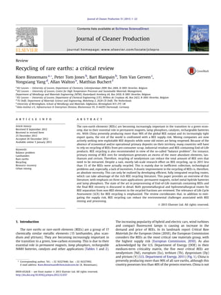
- 4. were being recycled in 2011 (so called average End-of-Life functional recycling, referred to as urban mining in Fig. 3). This is mainly due to inefficient collection, technological difficulties and, especially, a lack of incentives (Graedel et al., 2011a, 2011b; Reck and Graedel, 2012). A drastic improvement in End-of-Life recycling rates for REEs is a strategic necessity, even more so in countries possessing no or few rare-earth deposits. This can only be realized by developing efficient, fully integrated recycling routes. Recycling of REEs is important in view of the efficient use of natural resources and to ensure a supply of these critical raw materials. A third reason is the so-called “bal- ance problem” (Falconnet, 1985). The demand and supply of the individual rare-earth elements have to be equal at any time. Oth- erwise there will be shortages or excesses of some elements. The REEs occur in different ratios in minerals and ores, reflecting the natural abundance of the elements. For instance, neodymium is much less common than lanthanum or cerium, so that mining of REE ores for neodymium also produces large amounts of lanthanum and cerium that need to be sold. Recycling of neodymium means that less REE ores need to be mined to meet the global demand of this metal. The balance problem also explains why even for countries with large primary rare-earth resources, such as China, recycling of REEs is becoming an issue (Xu and Peng, 2009). It also explains why REE mining companies such as Molycorp are interested in neo- dymium recycling from magnets. Compared with the primary extraction of REEs from ores, the recovery of REEs via technospheric/ urban mining has the advantage that there are no thorium issues and that the composition of the obtained REE concentrate is less complex. For instance, lamp phosphors contain mainly Eu, Tb, Y, Ce, La, but are devoid of Nd, Pr and Dy. This review presents the state of the art of the challenges and possible solutions associated with the recycling of the rare earths, as encountered during (mainly) lab-scale R&D efforts. Emphasis is placed on the three major applications of REEs (Table 2), being permanent magnets, nickel-metal hydride batteries and lamp phosphors, as present in End-of-Life products (e.g. electric vehicles, hard disc drives, fluorescent lamps) and/or preconsumer scrap (e.g. magnet swarf). Collectively they represent more than 80% of the rare-earth market in terms of value (38% for magnets, 32% for lamp phosphors and 13% for metal alloys). Progress on recycling of rare earths in other End-of-Life materials (CRT phosphors, catalysts, polishing powders, glasses) will be only briefly discussed. Rare earth recycling from new and landfilled industrial residues (e.g. red mud, phosphogypsum) is not addressed in this paper, even though the rare earth potential of these streams should not be under- estimated. An idealized and simplified recycling flow sheet is pro- vided in Fig. 4. End-of-Life products containing REEs are ideally preprocessed to deliver REE-rich recyclates that can be further processed to produce rare-earth oxides and metals, which sub- sequently can be re-used for the production of new lamp phosphors and master alloys. In the case where End-of-Life products con- taining REEs end up in Electric Arc Furnaces (EAFs) or non-ferrous smelters, REEs will typically revert to slag phases in low Fig. 1. DOE medium term (2015e2025) criticality matrix, showing the five most crit- ical rare-earth elements (Y, Nd, Eu, Tb, Dy). Reproduced with permission from (U.S. Department of Energy, 2011). Fig. 2. Comprehensive raw materials strategy targeting a diversified approach: primary mining, substitution, raw materials diplomacy and technospheric mining and recycling. K. Binnemans et al. / Journal of Cleaner Production 51 (2013) 1e224
- 5. concentrations. The economic recovery of these rare earths will be more difficult. 2. Recycling of permanent REE magnets The most common REE magnets are based upon neodymium- iron-boron (NdFeB) alloys (NdFeB magnets). NdFeB magnets are comprised of an Nd2Fe14B matrix phase, surrounded by a neodymium-rich grain boundary phase, with small admixtures of praseodymium, gadolinium, terbium, and especially dysprosium, as well as other elements such as cobalt, vanadium, titanium, zirco- nium, molybdenum or niobium (Gutfleisch et al., 2011; Buschow, 1994; Yu and Chen, 1995; Croat et al., 1984). The grain boundary phase can also contain copper, aluminum or gallium. Dysprosium is added to magnets to increase their temperature stability against demagnetization. The dysprosium content in NdFeB magnets widely varies, depending on the application (Table 3). There are also variations within one type of application. For instance, although many computer hard disk drives (HDDs) contain no dys- prosium, other HDDs may show small admixtures of dysprosium up to 1 atomic percent (1 at.%). NdFeB magnets have the highest energy product BHmax of all permanent magnets (200e440 kJ mÀ3 ), which is much higher than ordinary ferrite magnets (36 kJ mÀ3 ). NdFeB alloys can be manufactured into resin bonded magnets (containing 10% epoxy resin) or into fully dense sintered magnets. The other, less prevalent type of rare earth magnets are based upon samarium-cobalt alloys, which possess a high coercivity (resistance against demagnetization), good corrosion resistance and excellent thermal stability. There are two different SmCo alloys, which are used for permanent magnets. These are based upon SmCo5 or Sm2Co17. These magnets may contain admixtures of different transition metals, such as Fe, Zr and Cu. For specific applications the temperature and corrosion resistance of SmCo magnets constitute major advantages with respect to NdFeB magnets (e.g. on-board Fig. 3. Different ways to close materials loops in a circular economy: (1) direct recycling of preconsumer scrap and residues (e.g. slags), (2) urban mining of End-of-Life consumer goods and other products, (3) landfill mining of historically landfilled pre-consumer and post-consumer waste streams. Reproduced from (Jones et al., 2011). The present paper focuses on (2). Fig. 4. Closing the loop in the life cycle of rare earths in major technological applications. K. Binnemans et al. / Journal of Cleaner Production 51 (2013) 1e22 5
- 6. aircraft). SmCo magnets have energy products BHmax which range between 120 and 260 kJ mÀ3 . Due to the lower energy product and because SmCo magnets have traditionally been more expensive than NdFeB magnets, their market share is very small (less than 2%). Moreover, there have also been supply shortages for cobalt in the past. In Fig. 5, a simplified overall recycling flow sheet for the REE magnets is shown. Three different material flows are considered: (1) swarf originating from magnet manufacturing, (2) small mag- nets in End-of-Life consumer products, (3) large magnets in hybrid and electric vehicles, as well as in wind turbines. As discussed in detail below, direct recycling and re-use is only relevant for the large magnets. In all other cases, the REEs magnet alloys have to be further processed. For applications where there is a very narrow distribution in the composition of the REE magnets among the different manufacturers (as in the case of computer hard disk drives, HDDs), one can consider direct use of the alloy by powder processing or by remelting of the recycled magnets to REE master alloys for the production of new REE magnets. In other cases, it is recommended to separate the rare earths from the transition metals and other elements (e.g. boron) present in the magnet alloys. The recycled REE mixtures are then separated into the individual REEs (in general as rare-earth oxides). These rare- earth oxides can be transformed into new REE master alloys for magnet production, or can be used for other applications involving these elements. The manufacturing process of REE magnets pro- duces large amounts of scrap and other residues, because of the cutting, grinding and polishing operations. Up to 30% of the starting REE alloy can be lost during the manufacturing process. Recycling of this scrap is being performed by the magnet manufacturing com- panies, but only few details about the actual recycling processes have been disclosed (Bounds, 1994; Tanaka et al., 2013). For a long time, recycling of magnet production scrap was the only form of REE recycling. In Table 4, an overview of the advantages and disadvantages of the different recycling routes for REE magnets is given. 2.1. Preprocessing of End-of-Life REE magnets The most obvious approach to recycling of REE magnets would be to re-use the magnets in their current form/shape, but this option is only possible for large, easily accessible magnets used in wind turbines and possibly in large electric motors and generators in hybrid and electric vehicles ((H)EVs). However, the magnets used in these applications will be in service for long periods of time and are, therefore, not currently available in large quantities in scrap today. Most of the current stock of redundant NdFeB material is present in electronic goods such as loudspeakers, mobile phones and hard disk drives. Computer hard disk drives (HDDs) are prob- ably the most important source of REE scrap today regarding mass flows. HDDs are not only easy to identify, but they are also often already removed from Waste Electronics and Electrical Equipment (WEEE) and they have a rapid turnover (w5 years). HDDs are also the single largest user of NdFeB in electronic goods with around 600 million manufactured annually (Walton and Williams, 2011). With between 10 and 20 g of NdFeB in each HDD, this equates to 6000 to 12,000 tons of neodymium-iron-boron-alloy. There are two magnets in a HDD; a resin bonded magnet in the spindle motor, which spins the disk and a sintered magnet in the voice coil motor (VCM), which controls the reading head. Most scrap HDDs are shredded to destroy the data on the disk. However, as the magnets are brittle they break up into granules which are still permanently magnetic. This powder then sticks to the other ferrous waste con- tained in the electronics and/or to the shredder, making it very difficult to effectively separate it. Nearly all WEEE waste is currently shredded in this manner. Subsequently, further physical processes are applied including magnetic and electrostatic techniques in order to separate different metal fractions. The existing state-of- the-art technologies for processing of these shredder residues in order to extract precious and other metals are based on smelting Table 3 Typical dysprosium content in NdFeB magnets for different applications (Constantinides, 2011). Application Typical Dy content (%)a Hybrid and electric cars 8.7 Generators 6.4 Wave guides: TWT, undulators, wigglers 6.4 Electric bikes 4.1 Electric storage systems 4.1 Magnetic brakes 4.1 Magnetically levitated transportation 4.1 Motors, industrial, cars, etc. 4.1 Pipe inspection systems 4.1 Relays and switches 4.1 Reprographics 4.1 Torque coupled drives 4.1 Wind turbines 4.1 Gauges 2.8 Hysteresis clutch 2.8 Magnetic separators 2.8 Magnetic refrigerators 1.4 MRI scanners 1.4 Sensors 1.4 HDDs, CDs, DVDs 0.0 Transducers and loudspeakers 0.0 Toys and gadgets 0.0 a % of Dy compared to the other rare earths. Fig. 5. Simplified recycling flow sheet for REE magnets. K. Binnemans et al. / Journal of Cleaner Production 51 (2013) 1e226
- 7. operations, which use lead, copper and nickel as collectors for the valuable metals. However, the smelter flow sheets have not yet been developed for recovery of rare earths. In practice the REEs revert to the oxide phase (slag) in a diluted form. Therefore, the REEs are ideally removed from the waste streams at a pre-smelter stage, although REE-recovery from smelter slags should not be neglected either (as this is where REEs currently mainly end up, see Fig. 4). In order to remove REE magnets from End-of-Life products before shredding/smelting, the magnets have to be identified in the waste and then efficiently extracted for further re-processing techniques to be applied. The separation step for REE magnets was identified as one of the key barriers to a recycling operation for REE magnets at the EU-Japan-US Trilateral Conference on Critical Raw Materials (Oct. 2011, Washington DC). There is no evidence of an on-going commercial recovery activity, partly due to the low prices for REEs in the past and the complex physical binding structure for magnets in the End-of-Life products. Sintered mag- nets are difficult to separate from WEEE scrap due to the strong magnetic fields they generate and because they are glued into position. It would be possible to demagnetise the magnets by heating them to above 300 C but this would result in melting of organic binders and glues, which surround the magnets, thereby creating for example hydrocarbon containing vapors. Non-thermal demagnetization is therefore recommended, for instance by applying a strong magnetic field opposite to the original magnet- ization direction. Sintered magnets are sensitive to humid envi- ronments and are, therefore, normally coated with nickel (other coatings include tin, zinc, aluminum and nickelecopperenickel). The resin-bonded magnets generate weaker magnetic fields and therefore present challenges in terms of detection. Hitachi has developed dismantling technologies to recycle rare earth magnets from HDDs and compressors of air condi- tioners (Hitachi Ltd., 2010). Different machines were developed to separate and collect NdFeB magnets from HDDs and com- pressors. For HDDs, a drum-type unit spins to shake and prang the HDDs continuously, so that the screws that hold the com- ponents together loosen and the HDDs simply break up into the structural components (casing, disk, NdFeB magnet, etc.) by impact and vibration. Because the components containing NdFeB magnets emerge from the machinery separately, workers are able to pick out the desired components just by visual screening. The new machine, can take apart 100 HDDs per hour, whereas a person can manually disassemble only about 12 HDDs by hand in the same time. For compressors, the cutting machine is first used to cut through the casing, and the rotors, which contain NdFeB magnets, are manually exposed. Secondly, those rotors that contain NdFeB magnets are disassembled with a rotor ejecting machinery. Then, in order to safely collect the NdFeB magnets, the magnets are demagnetized. Finally, a NdFeB magnet remover causes a vibration to the rotor and only the NdFeB magnets inside the rotor are separated and collected. Hitachi is aiming to implement the new technique by 2013, and expects it will pro- vide some 60 tons of REEs per year, or about 10% of the entire Hitachi Group’s REE needs. Recently, the University of Birmingham has disclosed a technol- ogy which uses hydrogen at atmospheric pressure to separate sin- tered REE magnets from computer HDDs, producing a demagnetized hydrided alloy powder of NdFeB (Walton et al., 2012; Walton and Williams, 2011; Harris et al., 2012). During hydrogen processing, the Nd-rich grain boundary phase in the NdFeB magnets initially absorbs hydrogen forming NdH2.7. This produces an exothermic reaction, which results in the Nd2Fe14B absorbing hydrogen with an associated 5% volume expansion. The differential expansion between the surface and the bulk causes the surface material to break away into coarse granules/powder. When Ni-coated NdFeB magnets are processed in hydrogen the coating peels away from the surface as flat particles. In order to hydrogen-process HDDs they are first sectioned in order to remove the VCM corner of the HDD. This concentrates the REE content of the scrap and opens up the HDD to allow a route out for the hydrided NdFeB powder. After hydrogen processing the HDD sections are rotated in a porous drum in order to liberate the hydrided NdFeB powder and Ni flakes. Separation effi- ciencies of around 95% have been reported on small scale trials. Further physical processing techniques are then applied which reduce the Ni content to 325 ppm. The success of this technology depends on sufficient access for hydrogen and a route out for the hydrided NdFeB powder. The powder which is extracted from HDDs can be directly reprocessed from the alloy into new sintered magnets with mag- netic properties approaching the performance of the original magnets or into cheaper resin-bonded magnets of a lower mag- netic performance (Walton and Williams, 2011; Harris et al., 2012; Zakotnik et al., 2006, 2008, 2009; Sheridan et al., 2012; Walton Table 4 Overview of the advantages and disadvantages of the different recycling methods for REE magnets. Method Advantages Disadvantages Direct re-use in current form/shape Most economical way of recycling (low energy input, no consumption of chemicals) No waste generated Only for large easily accessible magnets (wind turbines, large electric motors and generators in hybrid and electric vehicles) Not available in large quantities in scrap today Reprocessing of alloys to magnets after hydrogen decrepitation Less energy input required than for hydrometallurgical and pyrometallurgical routes No waste generated Especially suited for hard disk drives (little compositional change over the years) Not applicable to mixed scrap feed, which contains magnets with large compositional variations Not applicable to oxidized magnets Hydrometallurgical methods Generally applicable to all types of magnet compositions Applicable to non-oxidized and oxidized alloys Same processing steps as those for extraction of rare earths from primary ores Many process steps required before obtaining new magnets Consumption of large amounts of chemicals Generation of large amounts of waste water Pyrometallurgical methods Generally applicable to all types of magnet compositions No generation of waste water Fewer processing steps than hydrometallurgical methods Direct melting allows obtaining master alloys Liquid metal extraction allows obtaining REEs in metallic state Larger energy input required Direct smelting and liquid metal extraction cannot be applied to oxidized magnets Electroslag refining and the glass slag method generate large amounts of solid waste Gas-phase extraction Generally applicable to all types of magnet compositions Applicable to non-oxidized and oxidized alloys No generation of waste water Consumption of large amounts of chlorine gas Aluminum chloride is very corrosive K. Binnemans et al. / Journal of Cleaner Production 51 (2013) 1e22 7
- 8. et al., 2012). However, the magnetic properties of the reprocessed magnets will be determined by the composition of the magnets in the waste electronics. It should be noted that the composition of magnets can vary significantly between different applications. Direct re-processing of the alloys is particularly suited to HDD scrap as it is believed that the composition of these magnets has changed little over the last 15 years. Another possible route out for the extracted powders would be to separate the rare earth metals from the extracted material. The fine powders which are produced during hydrogen processing would be more susceptible to chemical attack during the subsequent hydro- and pyrometallurgical pro- cessing routes. Although these chemical routes would require sig- nificant energy input compared to direct re-processing of the alloys, it would be possible to process mixed scrap feeds which contain magnets with a large compositional range, which would not be suitable for direct reprocessing. Many electronic applications have complicated architectures and often contain very small quantities of NdFeB (e.g. mobile phones). In order to access this material these devices are likely to require shredding. The removal of REE magnets from shredded/ mixed WEEE streams presents significant challenges as outlined for HDDs. However, if a process could be developed to extract these magnets efficiently then it would present a huge opportunity to harvest a large quantity of REEs. If it was possible to separate NdFeB magnets from shredded WEEE waste then it is unlikely that this material would be suitable for direct re-processing into new mag- nets from the alloy, due to the fact that the material is likely to have a high oxygen concentration, a high level of impurities and a wide compositional range. 2.2. Hydrometallurgical routes for recovery of REEs from permanent magnets The traditional route for recovery of rare earths from permanent magnets is via hydrometallurgy (Ellis et al., 1994; Bounds, 1994). These earlier studies have mainly focused on the relatively clean magnets and preconsumer production scrap (“swarf”), not the End- of-Life magnet scrap mixed with other waste materials such as shredder residues. The magnet alloys are dissolved in strong min- eral acids and the REEs are selectively precipitated as double sul- fates, oxalates or fluorides. This approach requires large amounts of chemicals. Ideally, the recycling process would allow selective dissolution the rare earths (and the valuable boron), leaving behind the iron. However, even selective leaching cannot avoid that also unwanted elements go into solution, for instance nickel and copper from the protective coating of the magnets, and boron has to be separated from the rare earths. The REE-rich leaching solution must be freed from non-REE elements, before it can be injected into an existing REE separation plant. The earlier literature on recycling of REEs from permanent magnets focused on the recycling of SmCo magnet scrap, rather than NdFeB magnet scrap, because of the higher intrinsic value of SmCo scrap and because NdFeB magnets were not yet that popular at that time. Both the recycling of samarium and cobalt from SmCo magnets was economically jus- tified in the early 1990s, whereas this was not the case for NdFeB magnets. Recycling of NdFeB scrap could only be justified for environmental reasons. NdFeB magnets contain on average 72 wt% of iron, which cannot be recycled as a marketable product and should be disposed of as a waste product. For a long time, neo- dymium was a cheap metal, priced much lower than samarium. However, in 2012, the situation is completely different. As men- tioned earlier, the share of SmCo magnets in the REE magnets market is currently less than 2%. The recycling of SmCo scrap is also made easier by the fact that this type of magnet contains in general only one rare earth (samarium). Furthermore, the SmCo magnets do not possess a protective coating. Besides neodymium, NdFeB magnets often contain admixtures of dysprosium, terbium or pra- seodymium, so that a mixture of rare earths is obtained after recycling. Moreover, the protective coating (very often nickel) also makes the recycling of NdFeB magnets more complex. Rhône-Poulenc (now Rhodia Solvay Group) developed an aque- ous process for the recycling of valuable elements from SmCo5 and Sm2(Co, Fe, Cu, Zr)17 swarf (Bounds,1994). The Sm/Co swarf is readily dissolved in mineral acids such as sulfuric, nitric, hydrochloric or perchloric acid. Samarium and the transition metals (Co, Fe, Cu) are dissolved whether present in the metallic oroxidic form in the swarf. Zr is not dissolved and can be separated from the solution by fil- tration. The selection of the specific acid primarily depends on the further processing of the solution. For instance, nitric or hydro- chloric acid are preferred for a solvent extraction process, whereas sulfuric acid can be used with selective precipitation. Samarium can be almost completely precipitated as an oxalateoras a sulfatedouble salt with an alkaline metal or ammonium. The oxalate can be pre- cipitated by the addition of oxalic acid. Samarium oxalate has a very limited solubility in any strong (non-oxidizing) mineral acid, even at relatively high acid strengths. From a samarium sulfate solution, the double salt Sm2(SO4)3$2Na2SO4$2H2O can be precipitated by addi- tion of sodium sulfate. Also other hydrates can be formed. Samarium oxide (Sm2O3) can be obtained by calcination of the oxalate or the sulfate double salt. The transition metals will not be precipitated by oxalic acid or by sodium sulfate under these conditions. The pre- cipitated samarium salts can be separated from the solution by fil- tration. Instead of selective precipitation, samarium can also be removed from the acidic solution by solvent extraction with tri-n- butylphosphate (TBP) or with di-(2-ethylhexyl) phosphoric acid as extractants (Bounds, 1994). Samarium is extracted selectively, leaving behind the transition metals. Lyman and Palmer (U.S. Bureau of Mines) developed an aqueous process for the separation of rare earths for bulk NdFeB magnet scrap (Lyman and Palmer, 1992; Ellis et al., 1994). The procedure begins with leaching the magnetic scrap in an aqueous H2SO4 solution. For dissolution of 1 kg of NdFeB scrap, 10 L of a 2 M H2SO4 solution are needed. This ratio allows complete dissolution of the scrap, while the pH is kept lowenough to prevent precipitation of Fe(OH)3. The final pH of the leach solution is then 0.2. For a higher acid molarity or a greater weight of scrap, the solubility products of neodymium and iron sulfate will be exceeded. The pH is then raised to 1.5 by NaOH, KOH or NH4OH, at which a neodymium alkali metal or ammonium sulfate double salt, Nd2(SO4)3$M2SO4$6H2O (M ¼ Na, K, NH4) is formed. Iron remains in solution as long as the pH does notexceed 2.0. The sulfate double salt can be converted to neodymium trifluoride, NdF3, (which is easy to filter) by leaching in HF solution. When other rare earths are present in the magnetic alloy (praseodymium, terbium or dysprosium), they can also be recovered as the rare-earth alkali double salt and be converted into the rare-earth fluoride. An additional advantage of fluoride salts is the fact that the light rare-earth metals are in general produced in the metallic state by metallothermic reduction of the rare earth trifluorides with calcium metal (calciothermic reduction). Following rare-earth precipitation, oxygen gas is bubbled through the leach solution containing iron at 90 C to fully oxidize divalent iron to trivalent iron. Iron will precipitate as yellow jarosite, NaFe3(SO4)2(OH)6, which is easier to filter than Fe(OH)3. Jarosite formation can also be induced by adding a hydrogen peroxide sol- ution to the iron-containing solution after removal of the rare earth sulfate double salts. The original magnet material contains boron, which does not precipitate and remains in solution. After the jarosite precipitation, some of it may be recovered as a form of a hydrated zinc borate by raising the pH. The sulfate double salt solution can also be treated with an aqueous oxalic acid solution. The rare earth oxalate is selectively precipitated, and the oxalate can be thermally K. Binnemans et al. / Journal of Cleaner Production 51 (2013) 1e228
- 9. decomposed to the corresponding rare earth oxide. If the alloy scrap includes iron and cobalt, iron can be selectively precipitated from the solution as jarosite, and cobalt can be extracted using a suitable organic extractant, such as CyanexÒ 272. Although the process is effective, the acid leaching step is time-consuming and large amounts of non-recyclable reagents (H2SO4, NaOH, HF) have to be used. The application of ultrasound during leaching may reduce the required process time. Tanaka and co-workers have shown that the application of ultrasound at 20 kHz and 600 W during acid leaching at room temperature resulted in complete terbium leaching within 60 min, an improvement of the non-sonicated process by a factor of 55 for HCl leaching and of 13 for HNO3 leaching (Tanaka et al., 2002). It is not efficient to take metallic material, to dissolve it in acid, fol- lowed by conversion into an inorganic salt, and finally reduction to the metallic state. However, the process works well with swarf materials, cutting, grinding and machining waste, which are highly contaminated and partly oxidized. An alternative way of recycling NdFeB magnets is to produce a neodymium-iron master alloy. In this process the magnet scrap is dissolved in HNO3, and addition of HF results in the formation of a neodymium-iron fluoride double salt (Ellis et al., 1994). This double salt is dried and calciothermically reduced to the metallic state. This neodymium-iron master alloy can be used directly for the production of new NdFeB magnets. In a process developed by Rhône-Poulenc, it is suggested to calcine the NdFeB swarf so that all metals are oxidized, but at a temperature low enough to avoid extensive sintering and to preserve the granular nature of the material (Bounds,1994). The rare-earth oxides are then selectively leached at ambient pressure in HCl, H2SO4 or HNO3. The insoluble iron oxides are separated from the pregnant leach solution and discarded. The rare-earth-rich solution is then injected in an existing rare earth separation plant, so that the rare earth values contained in the swarf can be accomplished without significant capital investment. The advantage of this process is the recovery of the rare earths in high purity solutions, marketable to any other application. The main disadvantage is the cost to pretreat the swarf by calcination to permit the selective dissolution step and the gen- eration of waste that needs to be discarded. In a modified process, the NdFeB alloy is totally dissolved in a mineral acid such as HCl, H2SO4 or HNO3. Iron is precipitated as jarosite and removed from the solution by filtration. The iron can be leached again in HCl to produce FeCl3 that can be sold to the water treatment industry. The REE solution is injected in the liquid stream of a solvent extraction process of a rare earths separation plant. Itakura et al. have hydro- thermally treated commercially available Ni-coated NdFeB sintered magnets under the optimum conditions at 110 C for 6 h in an aqueous solution containing 3 M of HCl and 0.2 N of oxalic acid (Itakura et al., 2006b). The NdFeB magnet went into solution and neodymium formed a precipitate of neodymium oxalate. More than 99% of the neodymium present in the magnet was recovered. Boron could be recovered from the highly acidic waste water by addition of Ca(OH)2 as mineralizer, resulting in the precipitation of para- sibirskite, CaB2O5$H2O (Itoh et al., 2010; Itakura et al., 2006a, 2006c, 2007). The recovery of iron and nickel was not addressed in detail, but the authors mention that these metals can be precipitated as oxalates at less acidic conditions than neodymium. Another study indicated that selective leaching of neodymium from roasted NdFeB magnets was possible with a 0.02 mol LÀ1 HCl solution in an auto- clave at 180 C. More than 80% of the neodymium and dysprosium, and less than 10% of the ironwent into solution (Koyama et al., 2009). Also in this case, ultrasound can be used to increase the leaching rate, as was shown by Gasgnier and co-workers who performed rare- earth oxide leaching with an acetic acid solution and found a four times increase of leaching yield for terbium and over 70 times for praseodymium when applying 30e80 kHz ultrasound energy (Gasgnier et al., 1994). Ionic liquids offer a high potential for make solvent extraction processes more efficient, including the extraction of rare earths (Baba et al., 2011a; Binnemans, 2007). Ionic liquids are solvents that consist entirely of ions. They have unique properties such as a very low vapor pressure and an intrinsic electric conductivity. Ionic liquids could replace the organic phase in liquideliquid extraction processes, resulting in safer systems due to their non-volatility. Although most extraction experiments have been performed at a very small laboratory scale, Binnemans and co-workers have recently shown that ionic liquid extraction processes are also fea- sible at a larger scale (Wellens et al., 2012). Kubota, Goto and co- workers developed an ionic liquid-based supported liquid mem- brane (SLM), consisting of N,N-dioctyldiglycolamic acid (DODGAA) dissolved in the ionic liquid 1-octyl-3-methylimidazolium bis(tri- fluoromethanesulfonyl)imide, that showed a high permeability for rare-earth ions over iron(III) ions (Baba et al., 2011b). It has been suggested that this system could be used for the recovery of rare earths from leach liquors of magnet scrap containing a large amount of iron. 2.3. Pyrometallurgical routes for recovery of REEs from magnets Pyrometallurgical routes (high-temperature routes) have been developed as an alternative for the hydrometallurgical routes. Whereas the hydrometallurgical processes are very comparable to those used for the extraction of REEs from minerals, the main disadvantages of the hydrometallurgical routes are that large amounts of chemicals are required and that for the recycling of REE magnets the alloys first have to be converted into oxides (or chlorides or fluorides) and then reduced back to the metal. Some of the pyrometallurgical routes allow remelting of the REE alloys (direct melting) or extraction of the REEs from transition metals in the metallic state (liquid metal extraction). Other pyrometallur- gical routes are more suitable for recycling of REEs of partly oxidized REE magnet alloys (electroslag refining or the glass slag method). 2.3.1. Electroslag refining When the material to be recycled is available as relatively clean pieces, electroslag refining is a viable process for upgrading scrap (Ellis et al.,1994). In this process, scrap material is melted either as a consumable electrode or by addition to a molten bath. A reactive flux is used to remove carbon, hydrogen, nitrogen and oxygen and metallic impurities, such as Li, Na, Al, Zn, Mg, Ca and Si. The flux used is a molten mixture of CaCl2 and CaF2, to which optionally a rare-earth fluoride is added. In the case of arc melting of a con- sumable electrode, a water-cooled chill mold has been used so that, as the scrap is melted from the electrode, the molten material passes through a slag layer and into a shallow molten pool where it quickly solidifies. This process allows the impurities to float off the molten metal droplets and become trapped in the slag layer as the droplets pass through the slag. In the case of adding slag material to a molten bath, a similar procedure is used, but the material must be held in the molten state for some time to allow the impurities within the metal to react with the slag. After sufficient time of slag- metal reaction and separation, the metal is transferred from the crucible into a water-cooled chill mold by pour casting. This leaves the impurities and slag floating at the top of the molten metal bath during casting. The process is best suited for large, relatively clean scrap materials, for instance magnets broken during the manu- facturing process. Nevertheless, the electroslag refining procedure is not very effective for swarf materials, due to their fine particulate nature and very high levels of contamination. The process does not lend itself to the separation of the rare earths from the transition metals. Hence, if a material is being recycled for either its rare earth K. Binnemans et al. / Journal of Cleaner Production 51 (2013) 1e22 9
- 10. or transition metal value, as an input for the production of an unrelated alloy, this technology is not very suitable. However, for a closed loop recycling of large volumes of high quality material, electroslag melting shows considerable promise. 2.3.2. Liquid metal extraction The liquid metal extraction process has been developed to over- come the disadvantages of the aqueous processing and electroslag remelting technologies (Ellis et al., 1994). The goal was to develop a process that would allow the handling of a wide variety of scrap feed materials, from swarf to ingots, thereby producing a very clean material, i.e. with a low carbon, nitrogen and oxygen content and free of unwanted intermetallic compounds. The new process also had to eliminate the need to return from an inorganic compound to a metal using a reduction step. The liquid metal extraction process is comparable with conventional liquideliquid solvent extraction, but based on liquid metal solvents. Essentially this process consists of selective dissolution of the rare-earth alloy by a liquid alloy system. The rare earths and transition metals distribute themselves between two immiscible liquid metal phases. Bayanov and co- workers studied in the 1960s the distribution coefficients for the rare earths from lanthanum to lutetium in zinc-lead melts (Bayanov and Serebrennikov, 1964; Bayanov et al., 1966). After dissolution of the rare-earth alloy, the zinc-rich and the lead-rich phases sepa- rated by density and the dissolved metals were removed by dis- tillation or sublimation. The zinc and lead metals can be recycled in the process. The rare-earth elements have a strong tendency to dissolve in the zinc-rich phase. For instance, the distribution coef- ficient Kd ¼ CZn/CPb at 500 C is 5000 for lanthanum, 4000 for neodymium and 3100 for samarium. Unfortunately, several tran- sition metals have an even larger tendency to get dissolved in the zinc phase: the Kd values for iron, cobalt and nickel all exceed 10,000. Therefore, the zinc-lead system is not suitable for the separation of rare earths and transition metals. The Ames Labo- ratory (Iowa State University, USA) has developed a process based on a liquidesolid reaction system to recycle the rare earths from Nd2Fe14B and other alloys (Xu et al., 2000; Xu, 1999). To remove neodymium from Nd2Fe14B, liquid magnesium (melting point: 649 C) is used as the extraction reagent. After a rinse in an organic solvent bath to remove machining lubricant residues, crushed NdFeB magnet scrap particles are immersed in liquid magnesium at 800 C, or magnesium is melted over the NdFeB magnet scrap. Neodymium is soluble in liquid magnesium up to 65 at.% at 800 C (Okamoto, 1991), whereas iron is essentially insoluble (less than 0.035 at.% at 800 C) in molten magnesium (Nayeb-Hashemi et al., 1985). The liquid magnesium leaches the neodymium from the NdFeB magnet scrap particles. The liquid magnesiumeneodymium alloy can then be poured off, leaving the iron-boron particles behind. After separation of the liquidesolid phases, neodymium can be recovered from magnesium by vacuum distillation of mag- nesium. Alternatively, the resulting magnesium alloy enriched in neodymium (up to about 30%) can be used as feed material for the magnesium casting industry. Several magnesium alloys contain up to 2 wt% of neodymium. The residual iron-boron scrap can be recycled as well, particularly for low-grade iron castings where composition is not critical. This process has some significant advantages over aqueous processing technologies, because the liquid metal solvent can be recycled and the waste streams are kept to a minimum. These advantages should be weighed against the drawbacks of high temperature liquid metal processing and energy costs of the magnesium distillation if pure rare-earth alloys are the ultimate target. The process has not been commercialized for REE recycling yet. Disadvantages of this process are that it cannot be applied to (partly) oxidized NdFeB scrap and that the process is relatively slow (24e72 h). Japanese researchers have further developed the magnesium extraction method to a continuous extraction process (Takeda et al., 2006; Okabe et al., 2003a, 2003b), and determined the phase equilibria in the FeeMgeNd system at 1076 K (Takeda et al., 2005). The continuous extraction process with liquid magnesium is reminiscent of the continuous solideliquid extraction process with a Soxhlet extractor in organic chemistry, but now with liquid magnesium instead of an organic solvent. The process takes advantage of the high vapor pressure of magnesium (0.73 atm at 1300 K) and the very low vapor pressure of neodymium (less than 10À6 atm at 1300 K). The extraction appa- ratus has a simple design and is sealed during the extraction process. The magnesium extraction agent is circulated due to a temperature difference in inside the reaction vessel. The authors propose not to use pure magnesium for the extraction process, but rather magnesium alloy scrap, for instance from recycled laptop casings. Instead of liquid magnesium, it is also possible to use liquid silver (melting point: 962 C) for the direct extraction of neo- dymium from NdFeB (Takeda et al., 2004). Silver will dissolve neodymium, but not iron (or boron). Neodymium can be separated from the silvereneodymium alloy by oxidation of neodymium to Nd2O3, which is not soluble in molten silver. Although silver is more expensive than magnesium, replacement of magnesium by silver seems to be an interesting option for an industrial liquid metal leaching process, because of the easy recyclability and re-use of the silver metal. However, it should be noted that the end product of this process is a rare-earth oxide, as opposed to a rare-earth metal for the magnesium solvent method. Therefore, depending on the particular recyclate and the targeted end-product of the recycling flow sheet e mixed oxide, pure oxide, rare-earth alloy or pure rare- earth metals e either the magnesium process or the silver process is to be preferred. In another study, scrap of sintered NdFeB mag- nets have been melted with silicon or titanium (by inductive melting in an argon atmosphere) and solidified to form silicon-iron or titanium-iron intermetallic compounds, which can be used as microwave absorbing materials (Miura et al., 2006; Horikawa et al., 2006; Machida et al., 2003). 2.3.3. Glass slag method In the glass slag method, the REE alloy is brought into contact with a molten flux that is able to selectively dissolve the rare earths from the alloys and that shows the tendency to supercool to a glass. Saito et al. successfully extracted neodymium from NdFeB alloys by reaction of the alloy with molten boron trioxide, leaving behind a-Fe and Fe2B phases with a neodymium content of less than 0.01 wt% (Saito et al., 2003c). Extraction with molten boron trioxide has also been applied to samarium-iron (Saito et al., 2005a), samariumeironenitrogen (Saito et al., 2005b), terbiumeiron (Saito and Motegi, 2004), samariumecobalt (Saito et al., 2003b), and nickelelanthanum alloys (Saito et al., 2003a). The rare earths can be recovered from the boron trioxide glass slag by first dissolving the glass slag in sulfuric acid, followed by selective precipitation of the rare earths as a sulfate double salt or a hydroxide (Saito et al., 2006). However, this method generates a lot of inorganic waste (Saito et al., 2003c). NdFeB magnets can be converted into oxides (for instance by a roasting process) and the rare-earth oxides can be dissolved into molten LiFeREF3 fluoride, through the formation of oxyfluorides (Takeda et al., 2009a, 2009b). The dissolved oxides can be transformed into metals by molten salt electrolysis. 2.3.4. Direct melting Direct melting of relatively new and clean magnet scrap to pro- duce new magnet alloys is problematic, because of the oxygen and carbon content of the scrap. The oxygen will result in slag formation K. Binnemans et al. / Journal of Cleaner Production 51 (2013) 1e2210
- 11. and loss of a significant amount of rare earths due to the strong rare earths affinity for oxide slags. Smelting cannot remove carbon impurities and the carbon-containing alloys have inferior magnetic properties. To remove carbon and oxygen in NdFeB scrap, the scrap was first decarburized by heating so that the carbon is converted to carbon dioxide, followed by heating in a hydrogen atmosphere to reduce Fe2O3, followed by reduction of rare-earth oxides by calcium metal (Asabe et al., 2001; Saguchi et al., 2002, 2006; Suzuki et al., 2001). The reduced metal had a carbon content less than 0.001 wt% and an oxygen content of less than 0.1 wt%. Ni-coated sintered NdFeB magnets could be recycled for re-use by a melt- spinning method, in which the molten metal is rapidly cooled to thin ribbons by pouring on an internally-cooled rotating wheel (Itoh et al., 2004a, 2004b). The small amount of nickel present in the coating had hardly any effect on the magnetic properties of the newly prepared magnets. 2.4. Gas-phase extraction methods Besides the molten-state pyrometallurgical processes to recycle the rare earths from scrap, also gas-phase extraction methods have been developed to overcome the problems associated with a hydrometallurgical treatment of rare earth scrap (leaching with acid, precipitation, calcination of the precipitate, generation of large amounts of waste water). In analogy with a process to recover metals such as vanadium, tantalum, niobium, molybdenum, nickel and cobalt from scrap by chlorination (with Cl2 in a N2 stream) and carbochlorination (with Cl2 and CO in a N2 stream), whereby these metals are transformed into volatile chloride and separated based on differences in volatility, Adachi and co-workers developed a similar process to recycle rare earths from scrap (Adachi et al., 1991). The process for the recovery of transition metals is difficult to apply to rare earths, because rare earth chlorides are less volatile and can hardly be separated from other less volatile metal chlor- ides, especially from alkaline-earth chlorides. Extraction of the rare earths by chlorination requires relatively high temperatures and long reaction times. In addition, the rare-earth chlorides have a very similar volatility, so that mutual separation is not expected in the sublimation processes. However, it is known that the rare earth chlorides form volatile chlorides with alkali metal chlorides (e.g. KRECl4) and with aluminum chloride (REAlnCl3þ3n(g) with n ¼ 1e4) (Jiang et al., 1997). The complex formation leads to a huge increase in vapor pressure. For instance, in the presence of 1 atm of Al2Cl6(g), the volatility of NdCl3 is enhanced at 600 K by a factor of about 1013 . A stream of Cl2 (chlorinating gas) in N2 (carrier gas) is swept over the rare-earth scrap to chlorinate the oxides and metals to the corresponding chlorides. Al2Cl6 can be generated by chlorination of g-Al2O3. Subsequently, Al2Cl6 vapor is swept over the metal chlor- ides, transforming them into volatile complex adducts. The resulting gas-phase species are driven with the carrier gas along a temperature gradient in a tubular furnace and the metal chlorides are deposited at different places in the reactor tube. Upon deposi- tion, the complex chlorides are decomposed again in the anhydrous metal chloride and aluminum chloride. The anhydrous rare earth chlorides are concentrated in the deposits in the higher temper- ature zone (800e900 C) while cobalt and nickel chlorides are in the lower temperature zone (500e700 C). The purity of each of the recovered chlorides can be higher than 99%. The chlorides of other metals, such as iron, copper, zirconium, and aluminum, are con- densed at the outlet of the reactor (below 350 C). This process has been used by Adachi, Wang and others for the extraction of rare earths from Sm2Co17 and Nd2Fe14B magnet scrap (Murase et al., 1995), but also from concentrates, such as monazite (Ozaki et al., 1996; Murase et al., 1994; Murase et al., 1996), xenotime (Murase et al., 1996), and bastnäsite (Wang et al., 2002), used polishing powders (Ozaki et al., 1999a), and LaNi5 battery alloys (Murase et al., 1995). A major problem associated with this method is the high corrosivity of aluminum chloride, which hydrolyzes with formation of hydrogen chloride gas, even when the slightest amounts of water are present. In the gas-phase extraction, all the metals, rare earths and transition metals are converted into the corresponding chlorides, so that a lot of chlorine gas is consumed to transform for instance iron into iron chloride. Machida and co- workers, however, showed that neodymium can be selectively extracted from Nd2Fe14B by chlorination with ammonium chloride to NdCl3, leaving behind a-Fe and Fe-B residue (Itoh et al., 2009, 2008). NdCl3 can be removed by soaking in water. Uda described a process in which the REEs are extracted from oxygen-contaminated magnet swarf by selective chlorination with molten FeCl2 (Uda and Hirasawa, 2003; Uda, 2002). Activated carbon is added to the reaction mixture as de-oxygenating agent, to assist the conversion of rare-earth oxychlorides and rare-earth oxides by FeCl2 into rare- earth trichlorides. The rare-earth trichlorides formed can be sepa- rated from iron alloys and from the excess of FeCl2 by vacuum sublimation. In a next step, the anhydrous rare-earth trichlorides are hydrated and transformed into the corresponding rare-earth oxides by pyrohydrolysis. Hydrogen chloride is released during the pyrohydrolysis step, but it can be used for the conversion of metallic iron into iron(II) chloride (FeCl2). The FeCl2-process is a very interesting process, because of the closed chlorine-loop. The process can be operated so that only carbon and water are con- sumed, not chlorine. Alternatively, iron can be selectively extracted from Nd2Fe14B by carbonylation with CO, yielding the volatile Fe(CO)5 (Miura et al., 2008). 3. Nickel metal-hydride batteries The use of REE alloys in rechargeable nickel metal hydride (NiMH) batteries is based on their hydrogen storage properties. As a representative of hydrogen storage materials LaNi5 is capable of absorbing considerable amounts of hydrogen gas and forms a hydride LaNi5H6 (Yu and Chen, 1995). The hydrogen density in LaNi5H6 is even higher than in liquid hydrogen. A cubic meter of LaNi5H6 contains 88 kg of hydrogen, but the same volume of liquid hydrogen only weights 71 kg. The LaNi5-related hydrogen storage alloys absorb hydrogen gas rapidly at ambient temperature and their hydrides can be easily dehydrided by heating to temperatures between 50 and 100 C. LaNi5 based alloys are ideal hydrogen storage alloys, but their prices are high because pure lanthanum should be used as raw material. In order to reduce the price of the alloy, mischmetal is used to replace pure lanthanum, forming a family of mischmetal-Ni5 based hydrogen storage alloys. Misch-metal is a mixture of light rare earth elements (La, Ce, Pr, Nd) in the metallic state. The composition of mischmetal varies depending on the origin of the rare earth minerals and its processing. Its composition affects the characteristics of the hydrogen storage alloys. The higher the content of cerium and neodymium in misch-metal, the higher the dissociation pressure of the hydride will be. Nickel can be substituted by other elements (mainly Al, Mn, Cr, Fe, Co, Cu and Si). In the nickel metal hydride battery, the negative electrode is made of a hydrogen storage alloy, replacing the cadmium in the older NieCd rechargeable battery. In current NiMH batteries, multicomponent alloys such as La0.8Nd0.2Ni2.5Co2.4Si0.1, La0.8Nd0.2Ni2.5Co2.4Al0.1, MmNi3.55Co0.75Mn0.4Al0.3 or MmNi3.5- Co0.7Al0.8 (Mm ¼ mischmetal) are used instead of LaNi5. Although the hydrogen storage capacity of these alloys is lower than that of LaNi5, this disadvantage is outweighed by their much higher chemical stability in alkaline solution and lower tendency for pulverization. Hybrid electric cars represent more K. Binnemans et al. / Journal of Cleaner Production 51 (2013) 1e22 11
- 12. than half of the usage of NiMH batteries (57%). Every Toyota Prius contains about 2.5 kg of REEs (mischmetal) in its battery pack (Buchert, 2010). Spent nickel metal hydride batteries contain 36e42% nickel, 3e4% cobalt and 8e10% mischmetal consisting of lanthanum, cerium, praseodymium and neodymium (Muller and Friedrich, 2006). Until recently, the state-of-the-art industrial recycling of NiMH batteries was their use in stainless steel production as a cheap nickel source, and the rare earths were lost in the smelter slags (Muller and Friedrich, 2006). Several research groups have developed hydrometallurgical methods for the recovery of nickel, cobalt and rare earths from NiMH batteries. Lyman and Palmer investigated the leaching of NiMH scrap with different mineral acids (HCl, H2SO4, HNO3) to bring the rare earths into solution, and found that the best results could be obtained with a 4 M HCl solution (Lyman and Palmer, 1995). The dissolved rare earths could be precipitated from the chloride solution as phosphates by addition of phosphoric acid. Yoshida and co-workers precipitated the rare earths as double sulfates by addition of Na2SO4 (Yoshida et al., 1995). Zhang et al. developed a hydrometallurgical process for the separation and recovery of nickel, cobalt and rare earths from NiMH batteries. The electrode materials were dissolved in a 2 M H2SO4 solution (Zhang et al., 1999) or a 3 M HCl solution at 95 C (Zhang et al., 1998). The rare earths were recovered from the leach liquor by solvent extraction with 25% bis(2-ethylhexyl) phosphoric acid (D2EHPA) in kerosene, followed by stripping of the rare earths from the organic solution and precipitation with oxalic acid, and finally calcinations to convert the rare-earth oxalates into oxides. Li and co-workers reported a flow sheet for a hydrometallurgical procedure including leaching (3 M H2SO4), solvent extraction, evaporation and crystallization to recover nickel, cobalt and rare earths from NiMH batteries (Li et al., 2009). The rare earths are obtained as a chloride solution, with an overall recovery of 97.8%. Several other studies describe the dissolution of rare earths from NiMH batteries by leaching with H2SO4 or HCl (Tzanetakis and Scott, 2004; Poscher et al., 2011; Nan et al., 2006b, 2006a; Pietrelli et al., 2002; Pietrelli et al., 2005; Rodrigues and Mansur, 2010; Luidold and Antrekowitsch, 2012; Kaindl et al., 2012). Kanamori and co-workers dissolved battery waste in a 2 M HCl solution, and the dissolved metal ions were then pre- cipitated at pH 12 by addition of a 2 M NaOH solution at room temperature (Kanamori et al., 2009). Calcination at 1000 C gave a mixture of three types of crystalline phases, identified as NiO, CeO2 and LaCoO3. The nickel component was extracted from the precipitate by treatment with aqueous NH3. Heating of the filtrate gave a precipitate of Ni(OH)2, which was subsequently trans- formed into NiO by calcination. The filter cake, which was a mixture of CeO2 and LaCoO3 phases, was treated with HCl solution at room temperature so that LaCoO3 dissolved and CeO2 was left behind. Adjustment of the pH of the filtrate to 12 gave a precip- itate, which was converted to LaCoO3 by calcinations. Provazi and co-workers investigated the recycling of different metals includ- ing cerium and lanthanum from a mixture of different types of household batteries (Provazi et al., 2011). The battery waste was ground, briquetted and heated at 1000 C for 4 h under an inert atmosphere to eliminate volatile metals present, such as cadmium, zinc and mercury and to reduce the manganese oxides to MnO, which is soluble in sulfuric acid. The residue was sub- mitted to a magnetic separation and the remainder was leached with sulfuric acid. It was tried out to separate the metals in the leach solution by selective precipitation and solvent extraction. Solvent extraction with CyanexÒ 272 was found to be the most efficient method. Ekberg and co-workers developed a recycling flow sheet for nickel metal hydride batteries, consisting of dis- mantling of the battery, selective dissolution of electrode materials and separation of metals by solvent extraction (Larsson et al., 2012, 2011b, 2011a). In 2011, Umicore and Rhodia announced that they had jointly developed a process for recycling of rare earths from nickel metal hydride rechargeable batteries (Anonymous, 2011; Rhodia, 2011). Although the details of the process have not been revealed, it is based on Umicore’s patented Ultra High Temperature (UHT) smelting technology (Cheret and Santen, 2007). An industrial- scale pilot plant has been operational in Hoboken, near Antwerp (Belgium), since September 2011 and this pilot plant has an initial annual capacity of 7000 tons, corresponding to approximately 150,000 (hybrid) electric vehicle batteries or 250 million mobile phone batteries (Umicore, 2011, 2009). Not only nickel metal hydride batteries, but also Li-ion batteries can be recycled in this facility. At this moment, the process has been optimized for End-of-Life portable NiMH batteries. The batteries are fed in a vertical shaft furnace, together with a small amount of coke and a slag former (Cheret and Santen, 2007). At the bottom of the shaft furnace, oxygen-enriched air is injected into the furnace. The process requires relatively little external energy input, because the combustion of the plastic casing of the batteries and the organic electrolytes releases large amounts of energy. The metals are converted into a NieCoeCueFe alloy and a slag. The slag consists mainly of oxides of Ca, Al, Si, and Fe, and also contains Li and the rare earths (Verhaeghe et al., 2011). These oxide slags can be processed to recover the lithium and to produce rare-earth concentrates that are subsequently used as a feed in the rare- earth separation plant of Rhodia in La Rochelle (France). Recently, Honda Motor Co., Ltd. and the Japan Metals Chemicals Co., Ltd. announced that they will establish a recycling plant to extract REEs from used nickel-metal hydride batteries collected from Honda hybrid vehicles at Honda dealers inside and outside of Japan (Honda Motor Corporation Ltd, 2012). However, the recycling technology and process have not been disclosed. In Table 5, the different recycling technologies for NiMH batteries are compared. 4. Lamp phosphors Lamp phosphors in End-of-Life fluorescent lamps are a rich source of the heavy rare earths elements europium, terbium, and of yttrium. The recycling of REEs from lamp phosphors is more straightforward than the recycling of REEs from permanent mag- nets (Fig. 6). There are three options for recycling of the phosphor fraction of used fluorescent lamps: (1) direct re-use of the recycled Table 5 Overview of the advantages and disadvantages of the different recycling methods for REEs from NiMH batteries. Method Advantages Disadvantages Hydrometallurgical routes Low investment costs Recycling possible of different waste fractions (cathode and anode materials, metals from casing) that can be marketed separately Many manual operations are required for dismantling of batteries and separating the different components Large consumption of chemicals Pyrometallurgical routes Well-developed technology Energy recovery from plastic casings and other organic components Same processing steps used for extracting REEs from slags as from primary ores High investment cost for furnace REEs need to be extracted from slags REEs are obtained as mixtures and further separation is required K. Binnemans et al. / Journal of Cleaner Production 51 (2013) 1e2212
- 13. lamp phosphors in new lamps, (2) recycling of the individual phosphor components by physicochemical separation methods for re-use in new lamps and (3) chemical attack of the phosphors to recover their REE content (Table 6). Options (2) and (3) make use of hydrometallurgical processing routes, which are very similar to the processes used for the extraction of REEs from ores. However, the mercury present in the fluorescent lamps is a potential hazard, and full removal of mercury from the recycled lamp phosphors is a major challenge. Research on the recycling of rare earths from lamp phosphors is restricted to large fluorescent lamps and compact fluorescent lamps. No studies have been carried out yet on the recovery of rare earths from small fluorescent lamps used in LCD backlights or from phosphors used in white LEDs (Buchert et al., 2012). The recycling of phosphors from cathode ray tubes (CRTs) is discussed in Section 5.1. 4.1. Composition of reclaimed lamp phosphor powders Five rare-earth phosphors are often encountered in fluorescent lamps: the red phosphor Y2O3:Eu3þ (YOX), the green phosphors LaPO4:Ce3þ ,Tb3þ (LAP), (Gd,Mg)B5O12:Ce3þ ,Tb3þ (CBT), (Ce,Tb) MgAl11O19 (CAT) and the blue phosphor BaMgAl10O17:Eu2þ (BAM) (Justel et al., 1998; Yu and Chen, 1995; Ronda, 1995). A less common blue phosphor is the chloroapatite (Sr,Ca,Ba,Mg)5(PO4)3Cl:Eu2þ . Lamps produced by non-Chinese manufacturers often contain the halophosphate phosphor (Sr,Ca)10(PO4)(Cl,F)2:Sb3þ ,Mn2þ , which is a broad-band white emitter. Often this halophosphate phosphor is mixed with Y2O3:Eu3þ to obtain a good color-rendering. The frac- tion of the halophosphate phosphor in the recycled phosphor fraction can be higher than 50 wt%, but it does not contain any REEs and is therefore of low intrinsic value for recyclers. On the other hand, Y2O3:Eu3þ has the highest intrinsic value, because it contains large concentrations of yttrium and europium, and represents the main REE-containing phosphor in the recycled phosphor frac- tion (up to about 20 wt%). The recycled lamp phosphors contain significant amounts of alumina (Al2O3) and silica (SiO2) that is used in the barrier layer. The barrier layer is present between the phosphor layer and the glass tube. Its main function is to protect the glass envelope against attack by mercury vapor, and thus pre- venting mercury depletion of the lamp and reduction of the lumen output of the lamp. The barrier layer also improves the efficiency of the lamp by reflecting back the UV light that passes through the phosphor layer to the glass layer. End-of-Life fluorescent lamps are collected in many countries, because they are hazardous waste, due to their mercury content. After collection, the lamps are being processed by specialized companies to recycle glass, metal (filaments, supply electrodes, caps), plastics (caps, insulators), phosphor powder and mercury. Clean glass can be used for the production of new lamps, and other glass pieces can be used for making new glass products. Metal parts Fig. 6. Simplified recycling flow sheet for REE lamp phosphors. Table 6 Overview of the advantages and disadvantages of the different recycling methods for lamp phosphors. Method Advantages Disadvantages Direct re-use Very simple method No chemical processing required Only applicable to one type of fluorescent lamps, because different lamps make use of different phosphor mixtures Phosphors deteriorate over the lifetime of the lamp Separation of phosphors in individual components Relatively simple process No or limited amounts of chemicals are consumed Very difficult to obtain very pure phosphor fractions Separation process may change the phosphor particle size Phosphors deteriorate over the lifetime of the lamp Recovery of REE content Generally applicable to all types of phosphor mixtures Same processing steps as those for extraction of rare earths from primary ores Gives very pure rare-earth oxides that can also be used for other applications Many process steps required before obtaining new lamp phosphors Consumption of large amounts of chemicals Generation of large amounts of waste water K. Binnemans et al. / Journal of Cleaner Production 51 (2013) 1e22 13
- 14. are sent to metal recycling facilities and plastic parts are burnt for energy recovery. The recycling of the lamp phosphor powders and mercury are discussed in this review. Various methods are being used for the recycling of the different materials fractions of the End- of-Life fluorescent lamps. Linear tube lamps are relatively easy to recycle, by cutting of the ends of the tube, and blowing the phos- phor powder out (“end cut” method). Recycling of other shapes of lamps and especially the compact fluorescent lamps (CFLs, also called energy saving lamps) is more problematic. Most of these used lamps are crushed and shredded to recover glass cullet, alu- minum/metal materials, phosphor powder, and mercury. The bro- ken glass pieces are separated from the phosphor powder by a sieving operation. This sieving can be done via a dry or a wet process. However, it is not possible to remove the very fine glass particles from the lamp phosphor powder. The lamp phosphor fraction can contain up to 50 wt% of glass. This glass fraction lowers the intrinsic value of the lamp phosphors, because it dilutes the REE content. Furthermore, the fine glass particles render the compre- hensive recycling of the lamp phosphors more difficult, because treatment of the phosphor fraction with a Na2CO3 flux at high temperature will also transform the fine glass particles into soluble silicates, contaminating the feed solutions of the REE separation plant with silicon. The lamp phosphor powder constitutes about 3% of the mass of a fluorescent lamp. The production losses of REEs during the manufacturing of lamp phosphors and fluorescent lamps are relatively small, so that pre-consumer recycling of pro- duction waste is less of an issue for lamp phosphors (in contrast to magnet production, vide supra). In most countries, REEs are not being recovered from End-of-Life fluorescent lamps. The lamp phosphor fraction is landfilled or stored in containers, after treat- ment of the fraction to partially remove or stabilize mercury in a non-leachable form. The recycled lamp phosphor fraction has a very complex chemical composition, with large compositional variations between countries and between lamp recycling com- panies. Often, some lamp phosphor fractions are contaminated by zinc sulfide phosphors from cathode ray tubes (CRTs) of old color television sets and computer monitors. The zinc sulfide con- tamination causes problems when the phosphor fractions are dis- solved in acids, because highly toxic hydrogen sulfide gas is formed. Given the possible lamp phosphors, the recycled lamp phosphor fraction contains six rare-earth elements: La, Ce, Eu, Gd, Tb, Y. The other REEs are absent. In addition many non-REE elements are present: Al, Si, P, Ca in relatively large concentrations, and Ba, Sr, Mg, Mn, Sb, Cl, F, Hg, Pb, Cd in small to trace concentrations. Fe is largely absent in the lamp phosphor fraction. The starting products for phosphor production are largely purified from Fe, because even trace amounts of Fe would have a detrimental effect on the lumi- nescence efficiency of the phosphors. 4.2. Separation of phosphor powder mixtures by physicochemical methods Flotation (froth flotation) is widely used in the mining industry to separate valuable mineral particles from gangue material in crushed and ground ores, based on the ability of air bubbles to selectively adhere to specific mineral surfaces. The separation of lamp phos- phors particles by flotation is not as easy as separation of mineral ore particles, because all phosphor components are phosphates, oxides, aluminates or borates and thus rather similar in hydrophobicity, and because the phosphor particles sizes (10 mm) are much smaller than typical mineral particle sizes (w50 mm). Hirajima and co- workers investigated the feasibility to separate lamp phosphors by flotation (Hirajima et al., 2005a). They tested a calcium hal- ophosphate phosphor, non-specified red, green and blue rare-earth phosphors, mixtures of these phosphors and an actual phosphor mixture from a Japanese lamp recycler. The efficiency of the col- lectors dodecyl ammonium acetate, sodium dodecyl sulfate and sodium oleate was tested at different pH values, as well as the influence of the dispersant sodium metasilicate. The results are very dependent on both the type of collector used and the pH. For instance, at pH values below 4.5, the halophosphate phosphor could be totally removed from the mixture by flotation, leaving behind the rare-earth phosphor. However, under these acidic conditions, the blue phosphor is completely dissolved. With dodecylsulfate as col- lector, the halophosphate phosphor could be removed via the froth at pH values between 9 and 10. No conditions could be found to separate the different rare earth phosphors. Two-liquid flotation is more suitable than (froth) flotation for the separation of fine par- ticles (10 mm) and thus for the separation of lamp phosphor par- ticles. The flotation medium consists of a polar solvent (e.g. water or DMF) and a non-polar solvent (e.g. hexane, heptane, octane, nonane) that are not miscible and thus form two separate phases. The wettability of the particles can be manipulated by means of a sur- factant. To achieve separation, the powder mixture is shaken with a mixture of the two immiscible solvents, with a surfactant dissolved in the non-polar solvent. After agitation, the mixture is allowed to settle. One component of the mixture migrates toward the non- polar phase and remains at the interface of two phases, whereas the other component (or a mixture of components) remains in the polar phase. A mixture of Y2O3:Eu3þ , LaPO4:Ce3þ ,Tb3þ and (Sr,Ca,Ba,Mg)5(PO4)3Cl:Eu2þ could be separated by a two-step two- liquid flotation process, using N,N-dimethylformamide (DMF) as the polar phase and heptane as non-polar phase (Otsuki et al., 2008, 2007). In a first step, with dodecyl ammonium acetate as surfactant, the green phosphor LaPO4:Ce3þ ,Tb3þ could be collected at the interface, whereas the mixture of the two other phosphors was precipitated in the polar phase. In a second step, the blue phosphor (Sr,Ca,Ba,Mg)5(PO4)3Cl:Eu2þ was collected at the interface with sodium 1-octanesulfonate as surfactant, while the red phosphor Y2O3:Eu3þ remained in the DMF phase. Both the purity and the recovery of each phosphor were larger than 90%. The same mixture of three phosphors could also be separated by using other surfac- tants (Otsuki et al., 2008; Mei et al., 2009b, 2009a). Pneumatic sep- aration of a mixture of lamp phosphor particles in an air stream gave only moderate results, because the differences in particle size have a more pronounced effect on the separation than differences in den- sity between the particles: small heavy particles can settle at the same speed as large light particles (Takahashi et al., 2001). A mixture of phosphor particles has been separated in a dense medium (diio- domethane, r ¼ 3.3 g cmÀ3 ) (Hirajima et al., 2005b). The separation of the fine phosphor particles was accelerated by centrifugation and pretreatment of the particles with sodium oleate improved the separation efficiency. In diiodomethane, the halophosphate phos- phor (Sr,Ca)10(PO4)(Cl,F)2:Sb3þ ,Mn2þ (r ¼ 3.07 g cmÀ3 ) floats on the dense liquid, whereas Y2O3:Eu3þ (r ¼ 5.12 g cmÀ3 ), (Gd,Mg) B5O12:Ce3þ ,Tb3þ (r ¼ 5.23 g cmÀ3 ) and (Sr,Ca,Ba,Mg)5(PO4)3Cl:Eu2þ (r ¼ 4.34 g cmÀ3 ) sink. Disadvantages of this process are the high cost and toxicity of diidomethane. It has been proposed to separate the individual phosphors in a mixture by a method based on dif- ferences in magnetic susceptibility (Horikawa and Machida, 2011). Phosphors with a high terbium content such as LaPO4:Ce3þ , Tb3þ , (Gd,Mg)B5O12:Ce3þ ,Tb3þ and (Ce,Tb)MgAl11O19 are substantially more paramagnetic with respect to the europium-based phosphors or the halophosphate phosphors, and they are more strongly attracted towards magnetic fields. Although re-use of the separated pure phosphor compounds in new lamps may seem the preferred option for lamp phosphors, this approach cannot be recommended. First of all, none of the phys- icochemical separation methods gives a very pure end product. Secondly, the phosphors can partly deteriorate due to the long-term K. Binnemans et al. / Journal of Cleaner Production 51 (2013) 1e2214
- 15. exposure to UV radiation and bombardment by mercury atoms and ions. Thirdly, mercury tends to accumulate in the phosphor layer over time (vide supra). Fourthly, often different qualities of the same phosphor are present in the mixture. For instance, the purity of the used rare-earth oxides can differ from one manufacturer to the other. Finally, the separation methods often lead to changes in the particle size distribution of the phosphors. As a result, the quality of the recycled phosphor components is inferior to that of the starting product. Direct recycling of lamp phosphors is recommended only for the special case when the lamp producers can recycle the phosphors from their own End-of-Life fluorescent lamps. The Bel- gian waste-processing company Indaver has developed in close collaboration with Philips Lighting a process to recycle the phos- phors from Philips’ linear fluorescent tube lamps (Indaver, 2000). An innovative part of the process is that the fluorescent lamps are lighted up for a short moment to allow recording of the emission spectrum of the lamp. Because each phosphor mixture has a unique emission spectrum (fingerprint), the actual phosphor composition of the lamp can be determined from its emission spectrum. The end caps of the lamp are cut off and the phosphor powder is blown out and collected in different fractions for the different lamp types. At present, the process is not operational at a commercial scale. It can be concluded that the physicochemical separation methods can be useful for pretreatment of the phosphor mixture before recycling of its REE content, to remove the halophosphate phosphor fraction from the rare-earth phosphors. 4.3. Recovery of REEs from reclaimed lamp phosphors The reclaimed lamp phosphor mixtures can be considered as a rich source of REEs, especially of the heavy REEs (Eu, Tb, Y). In lamps with three-band phosphors, the concentration of rare-earth oxides in the lamp phosphors can be as high as 27.9 wt%, but the actual recycled phosphor fractions contain about 10 wt% of rare earths (calculated as oxide) (Wang et al., 2011). To recover the rare-earth values, the phosphor mixture has to be chemically attacked to bring the REEs into solution and the REEs are recovered from the solution by precipitation or solvent extraction. The treatment of the phosphors is similar to the ones used for the processing of REE ores. The resistance of the different phosphor components towards chemical attack by strong acids and other chemicals widely varies. The halophosphate phosphors and Y2O3:Eu3þ can be dissolved in diluted acids. However, the phosphate phosphor LaPO4:Ce3þ ,Tb3þ (LAP) and the aluminate phosphors (Ce,Tb)MgAl11O19 (CAT) and BaMgAl10O17:Eu2þ (BAM) are much more resistant toward attack by acids. Especially CAT is very difficult to dissolve. For dissolution of LaPO4:Ce3þ , Tb3þ the same processes can be used as for the pro- cessing of monazite ore, (Ce, La)PO4. Leaching experiments on three- band phosphor mixtures showed that hydrochloric acid (4 mol LÀ1 ) in combination with hydrogen peroxide (4.4 g LÀ1 ) is a strong leachant (Wang et al., 2011). LAP, BAM and CAT phosphors can be chemically attacked by heating them in molten sodium carbonate at 1000 C (Porob et al., 2012). The Y2O3:Eu3þ phosphor more readily dissolves in acids after mechanical activation by ball milling (Mio et al., 2001). The mechanochemical treatment creates disorder in the crystal structures and this allows dissolution under milder conditions. Rabah studied the recovery of yttrium and europium from spent fluorescent lamps by pressure leaching with a H2SO4/ HNO3 mixture (Rabah, 2008). Autoclave digestion of the phosphor mixture (consisting of Y2O3:Eu3þ and a halophosphate phosphor) in an acidic mixture for 4 h at temperature of 125 C and a pressure of 5 MPa dissolved 96.4% of the yttrium and 92.8% of the europium present in the mixture. Shimizu and co-workers carried out work on the recovery of REEs from lamp phosphors by extraction with supercritical carbon dioxide containing tri-n-butyl phosphate (TBP) complexes of nitric acid and water (Shimizu et al., 2005). More than 99.5% of the yttrium and europium present in the phosphor mixture could be extracted after 2 h of leaching at 15 MPa and 60 C. Control experiments with TBP/HNO3/H2O at atmospheric pressure allowed to extract less than 40% of europium and yttrium. De Michelis and co-workers carried out leaching tests on phosphor powders with different acids (HCl, HNO3, H2SO4) and ammonia to find the con- ditions for the most efficient recovery of yttrium (De Michelis et al., 2011). Leaching with ammonia gave very low yttrium recovery, whereas leaching with the different acids gave good results. Nitric acid is able to bring the largest quantities of yttrium into solution, but toxic vapors are formed. Hydrochloric and sulfuric acid behave similar in bringing yttrium into solution. However, leaching with sulfuric acid is to be preferred, because it leads to less co-dissolution of calcium, lead and barium. Yang and co-workers showed that the large amount of Al2O3 present in the phosphor mixture (from the barrier layer) is an advantage if the phosphors are dissolved in nitric acid, because the Al(NO3)3 that is formed can act as a salting-out agent for the extraction of rare earths from the aqueous phase to an organic phase by solvent extraction (Yang et al., 2012). Salting-out agents increase the efficiency of a solvent extraction process. OSRAM (owned by Siemens) developed a process to recover all REEs from used phosphors (Otto and Wojtalewicz-Kasprzac, 2012). After mechanical separation of the coarse parts of the fluorescent lamps, the phosphors powders are sieved with a mesh width between 20 and 25 mm. The different phosphor components are removed by several selective leaching steps. The halophosphate phosphor is dissolved in a dilute hydrochloric acid solution, at temperatures below 30 C. Under these conditions, Y2O3:Eu3þ is not or only slightly attacked, whereas the other rare-earth phosphors are not attacked at all. Y2O3:Eu3þ can be dissolved in diluted hydrochloric or sulfuric acid, at temperatures between 60 and 90 C. LaPO4:Ce3þ ,Tb3þ can be dissolved in hot concentrated sulfuric acid, at temperatures between 120 and 230 C. The aluminate phosphors (Ce,Tb)MgAl11O19 and BaMgAl10O17:Eu2þ can be attacked by a 35% sodium hydroxide solution at 150 C in an autoclave, or in molten alkali. The OSRAM patent describes different alternative routes to attack the phosphor components and to deal with impurities, such as large concentrations of calcium salts. Rhodia (Solvay Group) developed a flow sheet for the recovery of REEs from a mixture of halophosphate and rare-earth phosphors (Braconnier and Rollat, 2010). The phosphors are attacked by hot nitric acid (or hydro- chloric acid), and finally by a hot concentrated sodium hydroxide solution or by molten sodium carbonate. The rare earths are recovered from the leach solutions for further separation into the individual elements by a solvent extraction process. Rhodia has announced to start up two dedicated facilities for the REE recovery from End-of-Life fluorescent lamps in La Rochelle and Saint-Fons (France). The Rhodia process is optimized for recycling of REEs from lamp phosphors from French End-of-Life lamps, but the lamp phosphor composition varies widely throughout Europe. More work to commercially recycle lamp phosphors is thus still clearly required. 4.4. Mercury removal from lamp phosphors Mercury removal is an issue closely related to the recycling of REEs from lamp phosphors. Mercury presents not only an envi- ronmental hazard because of its toxicity, but it is also an unwanted impurity in the solvent extraction batteries of a rare-earth sepa- ration plant. The mercury content of fluorescent lamps varies widely depending on the type of lamp (linear tubes versus compact fluorescent lamps), the band, the wattage and the year of manu- facturing (Nance et al., 2012). However, the general trend is a steady decrease in mercury content over the years due to more strict environmental laws. A US study from 1994 reveals that the mercury K. Binnemans et al. / Journal of Cleaner Production 51 (2013) 1e22 15
- 16. content in used fluorescent lamps at that time varied between 0.72 mg/lamp to 115 mg/lamp, with an average of 33 mg/lamp, whereas in new lamps the mercury content was between 14.3 and 44.8 mg/lamp, with an average of 25.19 mg/lamp (Battye et al., 1994). Since 2012, compact fluorescent lamps with a power lower than 50 W are not allowed to contain more than 3.5 mg/lamp, according to EU regulations. US 13 W spiral compact fluorescent lamps contain between 0.17 and 3.6 mg mercury per lamp (Li and Jin, 2011). OSRAM claims that its energy saving lamps (compact fluorescent lamps) contain less than 2.5 mg of mercury, with a volume of less than 0.2 mm3 . The concentration of mercury in old fluorescent lamps is relevant, because these old fluorescent lamps are still being processed by modern lamp recycling facilities. During the operation of the lamp, part of the mercury becomes chemically bound to the glass wall and to the phosphor particles, so that the mercury concentration in the phosphor layer increases over time (Thaler et al., 1995; Doughty et al., 1995; Dang et al., 1999, 2002; Hildenbrand et al., 2003; Hildenbrand et al., 2000). For compact fluorescent lamps, more than 85% of the mercury present in the lamp ends up in the phosphor layer when the lamp reaches the end of its lifetime (Rey-Raap and Gallardo, 2012). The phosphor powder that is adhering to the glass surface is much richer in mercury than the loose powder that is collected during crushing of the lamps (Jang et al., 2005). The concentration of mercury in the phosphor powder can be 40 times higher in an End-of-Life fluorescent lamp than in a new lamp (Raposo et al., 2003). Both Hg(0), Hg(I) and Hg(II) occur in spent lamps, but there is still disagreement con- cerning which of these species actually dominates in the phosphor powder (Raposo et al., 2003). Different processes have been developed for removal of mercury from the lamp phosphor frac- tion. Thermal treatment of the phosphor mixture for several hours at 400e600 C in a vacuum allows the removal of the largest part of the mercury (Kuehl, 1991; Indaver, 2000). However, full removal of mercury is only possible by heating the phosphor powder to at least 800 C to decompose the inorganic mercury compounds or to heat the phosphor powders with organic reducing agents (Fujiwara and Fujinami, 2007). Distillation and other heating processes for mer- cury removal require very complicated equipment, are very energy- consuming and they cannot be used when wet sieving procedures are being applied to separate the phosphors from glass and metallic parts in crushed fluorescent lamps. Wet-sieving technology is used by several European lamp collectors. The mercury in the acidic leaching solution obtained by dissolution of the lamp phosphor has to be removed by treatment of the solutions by mercury absorb- ents, such as resins with mercury-binding functional groups. 5. Other sources of REE-containing waste 5.1. CRT phosphors Compared to the recycling of phosphors from End-of-Life fluo- rescent lamps, relatively little research efforts have been devoted to the recycling of phosphors used in cathode ray tubes (CRTs) of color television sets and computer monitors. This is due to the fact that this application is sharply declining, because of the replacement of CRT-based screens by LCDs, LCD/LEDs and plasma discharge dis- plays. Moreover, only the red phosphor of color television tubes contains a rare earth, i.e. europium. The first red phosphor, YVO4:Eu3þ , was replaced by Y2O2S:Eu3þ due to the increased brightness of the latter phosphor (Bredol et al., 1994). The blue and green phosphors in CRTs are based on zinc sulfide: the green phosphor is ZnS:Cu while the blue phosphor is ZnS:Ag. As men- tioned above, the zinc sulfide phosphors cause problems during the acidic attack of the phosphor powder mixture in the recycling process, due to the release of toxic hydrogen sulfide gas. Moreover, also during the dissolution of Y2O2S:Eu3þ in acids, hydrogen sulfide is formed. A possible solution to the handling of the sulfide phos- phors could be by first oxidatively roasting the ZnS to ZnO in air at 900 C, as done in traditional zinc metal production. Resende and Morais investigated the leaching of coating powder samples col- lected from computer monitors (Resende and Morais, 2010). They found that 96 wt% of Eu and Y could be recovered by leaching with sulfuric acid at room temperature. Leaching at higher temperatures did not give substantially better results. A pregnant leaching sol- ution containing 16.5 g LÀ1 of Y and 0.55 g LÀ1 of Eu at a pH of 0.3 was obtained and it was indicated that this solution could be fur- ther processed by solvent extraction without additional treatment steps. Dexpert-Ghys and co-workers developed a recycling scheme to recover the Y2O2S:Eu3þ phosphor from CRTs and to transform it into Y2O3:Eu3þ phosphor for mercury-free applications under VUV plasma excitation (Dexpert-Ghys et al., 2009). They found that an alkaline attack of the CRT phosphor gave much better results than an acidic attack. Commercial recycling schemes for CRTs have been set up in different countries, but these are directed towards the recycling of the (lead-containing) glass and the metal values, not the phosphor powders (Menad, 1999). 5.2. Glass polishing powders An important bulk application of rare earths is the use of cerium oxide (ceria, CeO2) as a glass polishing powder. About 10,000 ton of cerium oxide polishing powder was produced in 2008 (Xu and Peng, 2009). For decades, a slurry of cerium oxide in water is being known as the best polishing agent for glasses (Horrigan, 1981; Niinisto, 1987). The polishing mechanism is both a combination of mechan- ical abrasion and chemical etching of the glass surface. Cerium oxide is heavily used in high-tech applications such as the polishing of glasses for LCD screens, car windows, mirrors, optical lenses, but also for several types of cut gemstones. Although this application does not require cerium oxide of a high purity (rather high concentrations of other rare earths can be tolerated), high-quality polishing pow- ders need to fulfill very strict requirements with respect to its par- ticle size distribution. These particle size requirements make the recycling of polishing powders for re-use in high quality applications difficult. Spent polishing powder is heavily contaminated by small silica particles originating from the polished glass surface, as well as alumina particles from hydrolysis of poly(aluminum chloride), which is added as a flocculant. Terziev and Minkova developed a flow sheet for the recycling of cerium oxide polishing powders, which include dissolution of the powder in a HNO3/H2O2 mixture, followed by precipitation of the rare earth as carbonates and transformation of the carbonates into oxides by calcination (Terziev and Minkova, 1997). This process allowed preparing about 0.8 kg of new polishing powder from 1.0 kg of polishing powder waste. Kato and co-workers investigated a process for the removal of silica and alumina impurities form spent cerium oxide polishing powder by treatment of the polishing powder with a concentrated sodium hydroxide solution (4 mol kgÀ1 ) at 50e60 C for 1 h (Kato et al., 2000b, 2000a). Under these conditions, silica and alumina went into solution, and cerium oxide could be recovered by filtration. Further heating of the alkaline solution resulted in precipitation of the dissolved alumina and silica as zeolite or hydroxysodalite. The authors claim that the regenerated cerium oxide powder could be re-used twice for glass polishing, without substantial loss of pol- ishing ability. In a follow-up study, the formation of hydroxysodalite was investigated in more detail (Kato et al., 2000c). Kim and co- workers describe a process for the recovery of cerium and other rare earths from spent polishing powder (Kim et al., 2011). Silica and alumina particles were removed by froth flotation and by dis- solution in a concentrated sodium hydroxide solution. The K. Binnemans et al. / Journal of Cleaner Production 51 (2013) 1e2216