Vip Mumbai Call Girls Navi Mumbai Call On 9920725232 With Body to body massag...
50.pdf
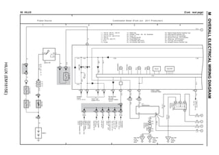
1. 1 2 3 4
50 HILUX (Cont. next page)
Interior Light
System<18–2>
∗ 5 : 1GR–FE
P ow er S ource C ombination M eter (From Jun. 2011 P roduction)
Headlight
System
<13–3><14–3>
R
Speedometer
Tachometer
Fuel
Temp.
Door
High
Beam
ID2
16
P–L
Engine
ECU
<
4–13>
<
5–12>
<
6–13>
<
7–7>
<
45–12>
<
47–12>
V–R
C25(C), C26(D)
ODO/TRIP
Buzzer
S 3
P–L
1 2
3
I 6
8 2J
W–R
1B
4
30A
AM2
R
1
1
2
30A
DCC
W
1 1A
Battery
W–R(∗1
∗61,
∗6,
∗7)
R
(∗1
∗62)
5 IG2
ST2
6
AM2
7.
5A
MET
2C
B
6
7.
5A
DOME
2
1
2Q
25
R
2D
1
B–O
2Q
10
2P
26
2Q
26
Transmission
Control
ECU
<
12–4>
<
44–4>
V–R
(∗4)
V–R
Combination Meter
Ignition SW
Speed Sensor
17 IF8
IF10
2 (∗1)
(∗6)
∗ 3 : 1TR–FE, 2TR–FE
BR
(∗1)
BR
(∗3)
Junction
Connector
J30(B),
J38(A)
∗ 4 : 1KD–FTV A/T, 2KD–FTV A/T
11 D 17 C 16 C 15 C 10 C 6 C 5 C
1 C
∗ 1 : 1TR–FE, 2TR–FE, 1GR–FE
6 B (∗3)
9 A
6 A (∗5)
7 B (∗3)
BR(∗7)
4WD
Control
ECU
(Rear
Diff.
Lock)
<
29–3>
V–R
2I
4
Theft
Warning
ECU<
30–3>
V–R
2P
4
∗ 6 : 1KD–FTV, 2KD–FTV
∗ 7 : 5L–E
(∗5)
B–O
A/C
Amplifier
<
39–7>
V–W
2P
10
IG+ SE
SI
Key Reminder
and Light
Reminder System
<32–3>
CPU
6 A 2 A
1 B
EC Rear Side
of the
Cylinder
Block
BR
BR
BR
BR
(∗7)
(∗6 ∗23)
(∗6 ∗24)
(∗6 ∗24)
W–B
BR
(∗6
∗24)
(∗6
∗24)
Radio
Receiver
Assembly
(∗53)
<
33–2>
V–R
2Q
4
∗23 : Australia, Europe, ∗58, ∗59, Kazakhstan
∗24 : Except ∗23
A/C
Control
Assembly<
42–5>
3 A
Junction
Connector
J
7(A),
J
8(B)
ED Rear Side
of the
Cylinder
Block
EG
Rear Side
of the
Cylinder
Block BR
(∗5)
(∗37)
∗37 : w/ Steering Pad SW
∗38 : Except Middle East
∗41 : w/ Automatic Light Control
∗42 : w/o Automatic Light Control
∗14 : Middle East
(∗42)
(∗41)
(∗41)
(∗38)
28 C
Engine
ECU
<
6–14>
<
45–12>
<
47–12>
P–L
(∗13)
ID2
15
R–B
R–B
31 C
(∗38)
IF3
11 (∗7)
(∗38)
(∗38)
(∗14)
(∗41)
(∗42)
∗53 : Radio Receiver Assembly Type
∗52 : Radio & Display Receiver Assembly Type
Radio
&
Display
Receiver
Assembly
(∗52)
<
33–2>
∗13 : Europe
∗59 : Morocco From Aug. 2012 Production
∗58 : South Africa w/ VN Turbocharger
∗61 : Before Aug. 2013 Production
∗62 : From Aug. 2013 Production
∗63 : Navigation Receiver Assembly Type
Navigation
Receiver
Assembly
(∗63)
<
33–2>
A
B
C
D
E
M
OVERALL
ELECTRICAL
WIRING
DIAGRAM
HILUX
(EM1815E)
2. 7 8
6
5
(Cont. next page)
50 HILUX (Cont' d)
T–BELT
Fuel
B–W
Engine
ECU
<
4–18>
<
5–14>
<
6–22>
<
7–8>
<
45–19>
<
47–22>
P
Engine
ECU
<
4–13>
<
5–13>
<
6–12>
<
7–8>
<
45–10>
<
47–10>
BR–Y
BR
BR
BR–Y
BA1
4
3 BA1
F13(A)
EC
1 EA1
L–R
2
1
F10
L–R
BR
BR–Y
BR
Fuel
Sedimenter
Level
Warning
SW
Fuel Sender Gage
(∗2)
(∗2)
(∗2)
Fuel Suction Pump
and Gage Assembly
F15(B)
(∗1)
B
3
3 A (∗2)
(∗1)
B
2
2 A (∗2)
Gage
(∗6)
(∗6)
C ombination M eter (From Jun. 2011 P roduction)
SRS
System
<
21–5>
Driver'
s
Seat
Belt
SRS
Seat
Belt
Warning
System<
21–3>
C25(C), C26(D)
J 1
2
1
W–G
W–G
F
4
1
5
Left Side of the
Fender Apron
EB
W–B
W–B
(w/
SRS)
Fuel
Filter
Combination Meter
Fuel
Filter
Warning
SW
Junction
Connector
(∗2)
(∗2)
(∗2)
(∗2)
(∗6)
(∗6)
23 D 24 D 9 C 19 D 20 D 18 D
13 ID2
Accessory
Meter
<
34–3>
Taillight
and
Illumination
System
<
17–7>
INJ
Fuse
<
4–2>
<
5–2>
Fuel
Injector
(No.
1)<
4–9>
<
5–7>
Engine
ECU
<
6–14>
<
45–12>
<
47–12>
L–B
P–G
B–R
L
L
G–B
23 C 2 C 3 C 7 C 4 C 11 C 14 C 20 C
∗ 2 : 1KD–FTV, 2KD–FTV, 5L–E
6 A
1 B 2 B
EH
BR
(∗7)
Rear Side
of the
Cylinder Block
BR(∗7)
ID1
11
W
34 C
W
Oil
Level
(∗13)
∗ 1 : 1TR–FE, 2TR–FE, 1GR–FE
B–O
(∗6)
(∗6)
J41(A),
J42(B)
Junction
Connector
OIL
CHANGE
(∗13)
(∗10)
(∗10)
(∗10)
(∗10)
(∗6
∗10)
1 B (∗16)
1 A (∗15)
2 A (∗15)
2 B (∗16)
Engine Oil
Level Sensor
E18(A), (B)
(∗13)
∗15 : 1KD–FTV, 2KD–FTV Europe
∗16 : 2KD–FTV Except Europe
120km/h
(∗14)
(∗14)
∗14 : Middle East
∗10 : w/ Multi Display
CPU
∗ 6 : 1KD–FTV, 2KD–FTV
7 IA1
IA1
8 (RHD)
(LHD)
17 IA1
IA1
9
BR
BR
BR
BR
(∗7)
(∗6 ∗23)
(∗6 ∗24)
(∗6 ∗24)
BR
(∗6 ∗23)
BR
(∗6 ∗23)
BR
(∗6 ∗23)
Rear Side
of the
Cylinder
Block
BR
(∗7)
BR
(∗6 ∗23)
∗ 7 : 5L–E
∗23 : Australia, Europe, ∗58, ∗59, Kazakhstan
∗24 : Except ∗23
∗13 : Europe
3 IF5
13 IF5
(∗49)
∗39 : Except Australia, Middle East
∗38 : Except Middle East
∗49 : w/ Rheostat SW
(∗51)
4WD
(∗51)
∗51 : w/ 4WD Part Time
(∗39)
C
21
B–O
(∗13)
(∗38)
(∗38) (∗38)
(∗38) (∗14)
∗59 : Morocco From Aug. 2012 Production
∗58 : South Africa w/ VN Turbocharger
∗60 : w/ Front Passenger Seat Belt Warning Lamp
D
28
D
14
Seat
Belt
Warning
System<
21–2>
(∗60)
(∗60)
(∗60)
(∗60)
A
B
C
D
E
M
HILUX
(EM1815E)
3. 9 10 11 12
50 HILUX (Cont' d) (Cont. next page)
Turn Signal and
Hazard Warning
Light System<16–3>
Turn
LH
Turn
RH
A/T
OIL
TEMP
Taillight and
Illumination
System<17–7>
J57
Illumination
Y
ID Instrument Panel
Reinforcement Center
W–B
ECT
and
A/T
Indicator
System
<
11–11>
<
12–7>
<
44–11>
(w/o
SRS)
W–B
(w/o
SRS)
W–B
W–B(w/o SRS)
LCD
Illumination
4WD
Junction
Connector
A/T
P
4WD
System
<
9–1>
<
9–2>
<
10–1>
<
10–2>
C ombination M eter (From Jun. 2011 P roduction)
8 C 12 C 24 C 25 C
19 C 22 C 25 D 13 C 18 C
N
D
4
(∗11)
3
(∗12)
3
(∗11)
2
(∗12)
2
(∗11)
L
(∗12)
L
(∗11)
R
P
ECT and A/T Indicator System
<11–11><11–12><12–7><12–8><44–11><44–12>
D
7 1 D
D
6 D
5 D
4 D
3 D
2
4WD System
<9–2><10–2>
Rear
Fog
Rear
Fog
Light
System
<
19–7>
10 D
Front
Fog
15 D
Front
Fog
Light
System
<
19–3>
(∗31)
(∗31)
(∗8)
(∗8)
(∗8)
(∗8)
(∗8)
(∗8)
(∗8)
(∗8)
(∗8)
(∗8)
(∗8)
(∗8)
(∗8)
(∗8)
(∗8)
(∗8)
(∗8)
(∗8) (∗8) (∗8) (∗8) (∗8)
Rear
Diff.
Lock
9 D
Rear
Differential
Lock
System<
29–4>
ECT
System
<
40–3>
CPU
C25(C), C26(D)
Combination Meter
(∗25)
W–G
32 C
W–G(∗25)
(∗26)
Taillight
and
Illumination
System<
17–7>
∗ 8 : w/ A/T Indicator Light
∗11 : 5A/T
∗12 : 4A/T
∗25 : w/o Daytime Running Light
∗26 : w/ Daytime Running Light
Illumination
(∗8)
(∗8
∗25)
(∗8)
(∗32)
(∗32)
(∗32)
(∗31)
(∗8 ∗48)
∗31 : w/o Optitron
∗32 : w/ Optitron
∗43 : ∗13 ∗14
∗46 : w/ Tail Lamp Position
∗47 : ∗25 ∗32
∗48 : ∗26 ∗32
∗50 : w/ 4WD Full Time
∗51 : w/ 4WD Part Time
(∗32)
(∗43)
(∗43)
(∗31)
(∗31)
(∗47)
Position
(∗8)
(∗46)
(∗46)
(∗50)
(∗51)
(∗48)
(∗48)
(∗51)
∗14 : Middle East
∗13 : Europe
22
20
21 IF8
IF8
19 (∗56)
(∗57)
∗57 : From Nov. 2011 Production
∗56 : Before Nov. 2011 Production
ECT and A/T
Indicator System
<11–12><12–8><44–12>
A
B
M
OVERALL
ELECTRICAL
WIRING
DIAGRAM
HILUX
(EM1815E)
4. 13 16
15
14
50 HILUX (Cont' d)
Engine
Control
System
<
4–8>
<
6–6>
<
47–6>
CRUISE
Engine
Control
System
<
4–8>
<
5–9>
<
6–7>
<
7–5>
<
47–7>
Charging
System
<
1–6>
Check
Engine
Charge
Brake
C25(C), C26(D)
1
Oil
Pressure
1
LG
LG–B
LG–B
W–B
LG
ID2
10
2
Right Side of the
Fender Apron
EA
ABS
System
<
20–2>
ABS
2S
1 2S
17
2L
1 2M
1
1
LG
(w/ ABS ∗22)
L–O Skid Control ECU
with Actuator
<20–5>
(w/
ABS)
(w/o
ABS)
R–G
R–G
W–B
(w/o
ABS)
Combination Meter
Brake
Vacuum
Warning
SW
Parking
Brake
SW
P
2
B
3
Brake
Fluid
Level
Warning
SW
B
2
(∗22)
37 C 8 D 39 C
Engine
Control
System
<
6–7>
<
7–5>
<
47–7>
Glow
(∗2)
40 C 38 C 36 C 35 C
1 B (Except ∗7)
1 A (∗7)
∗ 7 : 5L–E
∗13 : Europe
∗21 : w/ VSC
∗22 : w/o VSC
2
Brake
Vacuum
Warning
SW
B
9
LG
(∗21)
1
W–B
W–B
(∗21)
2R
1
14 IA1
IA1
9 (LHD)
(RHD)
LG
LG
Skid
Control
ECU
with
Actuator
<
41–4>
9 A
ABS
(w/
VSC),
TRC
and
VSC
System<
41–2>
26 C
W–B
(∗22)
9 B
B
12
A
7
Instrument Panel
Reinforcement Center
ID
W–B
W–B
W–B(w/o SRS)
C ombination M eter (From Jun. 2011 P roduction)
(∗21)
7 B
W–G(∗25)
W–G(∗25)
∗25 : w/o Daytime Running Light
∗ 2 : 1KD–FTV, 2KD–FTV, 5L–E
VSC
OFF
16 D
Slip
17 D
∗44 : w/ Cruise Control
∗45 : ∗13 ∗44
(∗21)
(∗21)
(∗21)
(∗21)
(∗55)
(∗55)
(∗21)
LG
(∗22)
DPF
33 C
Engine
Oil
Pressure
Sensor
E
4(A),
(B)
Engine
Control
System
<
47–6>
CRUISE
27 D
(∗45)
(∗45)
ABS
(w/
VSC),
TRC
and
VSC
System<
41–2>
Engine
Control
System
<
47–6>
∗52 : Radio & Display Receiver Assembly Type
∗54 : w/ Parking Assist (Rear View Monitor)
2R
17
LG
(∗54)
Radio
&
Display
Receiver
Assembly
(∗52)<
33–3>
14 IF5
Junction
Connector
J20(A),
J21(B)
∗55 : w/ Cruise Control Except Europe
(w/o ABS, w/o SRS)
Junction
Connector
J62(A),
J63(B)
21 D
Navigation
Receiver
Assembly
(∗63)<
33–2>
∗63 : Navigation Receiver Assembly Type
TRC
OFF
(∗21)
(∗21)
(∗21)
(∗21)
A
B
M
HILUX
(EM1815E)