SlideShare a Scribd company logo
1 of 1
Table 1: FMEA Summary of Redesigned TLS System
Ident. No. Item/Functional
Identification
Failure Mode Failure Cause Failure Event Target Action Required
A.1.2 Wingtip
protection
Delamination High peel stress Wingtip damage D Frequent inspection
A.2.1.1 Retracts and
deploys wheel
Stripped gear Excessive torque Landing gear does not
deploy
A Inspection on ground before take-
off or back-up actuator
A.2.2.1 Attach gear
frame to fuselage
Loose bolt Vibration from cyclic
loading
Frame detachment from
aircraft
A Implement lock wire for bolts
A.2.2.2 Landing load
distribution and
landing gear
placement
module
Column
buckling
Compressive stress
from landing impact
Fracture of gear frame
structure
A Increase frame structure thickness
or use of stronger material
A.2.2.3 Mount servo
motor to gear
frame
Loose bolt Vibration from
repeated landing
impact
Landing gear does not
deploy
A Implement lock wire for bolts
A.2.3.1 Secures landing
gear position
during
deployment
Shear failure Shear stress due to
landing impact
Landing gear collapse
upon touchdown
A Increase margin of safety or
thickness of pin
A.2.3.2 Attachment of
wheel to gear
frame
Buckling Compressive stress
from landing load
Sudden collapse of wheel
strut upon touchdown
A Increase strut thickness
A.2.3.2 Absorb landing
impact
Tire puncture Presence of foreign
object debris (FOD) on
landing runway
Loss of control during
ground roll
D Selection of tire with increased
thickness and inspection for FOD
on landing area.
A.3.1 Folds propeller
upon landing
Propeller does
not fold
Increased hinge joint
friction due to
corrosion
Propeller strike during
landing
D Frequent lubrication
B.1.1.2 keeps roof rack
attached to car
Shear failure Shear stress from
inertial and drag forces
of roof rack and
aircraft
Roof rack gets detached
from car
A, D,
P
Increase margin of safety for bolts
For the take-off subsystem, only B.1.1.2 was considered as the failure of all the other parts simply results in aborted take-off (stopping of the vehicle)
and no further damage on the aircraft or the operator,
Legend: A - Aircraft D - Downtime P - Personnel

More Related Content

Viewers also liked (10)

Techstorming: herramienta de Induct para innovar en la empresa en base a tend...
Techstorming: herramienta de Induct para innovar en la empresa en base a tend...Techstorming: herramienta de Induct para innovar en la empresa en base a tend...
Techstorming: herramienta de Induct para innovar en la empresa en base a tend...
 
Figures of speech (Semantics)
Figures of speech (Semantics)Figures of speech (Semantics)
Figures of speech (Semantics)
 
A Clean, Well Lighted Place
A Clean, Well Lighted PlaceA Clean, Well Lighted Place
A Clean, Well Lighted Place
 
FMEA
FMEAFMEA
FMEA
 
Yellow Wallpaper Lecture
Yellow Wallpaper LectureYellow Wallpaper Lecture
Yellow Wallpaper Lecture
 
Concept of Poetry- Wordsworth and Coleridge
Concept of Poetry- Wordsworth and ColeridgeConcept of Poetry- Wordsworth and Coleridge
Concept of Poetry- Wordsworth and Coleridge
 
Major Male Characters from "Tom Jones".
Major Male Characters from "Tom Jones".Major Male Characters from "Tom Jones".
Major Male Characters from "Tom Jones".
 
DIFFERENCE BETWEEN WORDSWORTH AND COLERIDGE'S CONCEPT OF POETRY
DIFFERENCE BETWEEN WORDSWORTH AND COLERIDGE'S CONCEPT OF POETRYDIFFERENCE BETWEEN WORDSWORTH AND COLERIDGE'S CONCEPT OF POETRY
DIFFERENCE BETWEEN WORDSWORTH AND COLERIDGE'S CONCEPT OF POETRY
 
Landing gear Failure analysis of an aircraft
Landing gear Failure analysis of an aircraftLanding gear Failure analysis of an aircraft
Landing gear Failure analysis of an aircraft
 
Resume_Ethan Gorham_4 26
Resume_Ethan Gorham_4 26Resume_Ethan Gorham_4 26
Resume_Ethan Gorham_4 26
 

More from Boon Siang Teh

Boon Siang Teh SOLIDWORKS Sample Work
Boon Siang Teh SOLIDWORKS Sample Work Boon Siang Teh SOLIDWORKS Sample Work
Boon Siang Teh SOLIDWORKS Sample Work
Boon Siang Teh
 
traverse_system_assembly_top_half view.PDF
traverse_system_assembly_top_half view.PDFtraverse_system_assembly_top_half view.PDF
traverse_system_assembly_top_half view.PDF
Boon Siang Teh
 
traverse_system_assembly_no_color.PDF
traverse_system_assembly_no_color.PDFtraverse_system_assembly_no_color.PDF
traverse_system_assembly_no_color.PDF
Boon Siang Teh
 
traverse_system_assembly_drawing.PDF
traverse_system_assembly_drawing.PDFtraverse_system_assembly_drawing.PDF
traverse_system_assembly_drawing.PDF
Boon Siang Teh
 

More from Boon Siang Teh (7)

absolutelyprintthis
absolutelyprintthisabsolutelyprintthis
absolutelyprintthis
 
Boon Siang Teh SOLIDWORKS Sample Work
Boon Siang Teh SOLIDWORKS Sample Work Boon Siang Teh SOLIDWORKS Sample Work
Boon Siang Teh SOLIDWORKS Sample Work
 
scaleduptestmodel.PDF
scaleduptestmodel.PDFscaleduptestmodel.PDF
scaleduptestmodel.PDF
 
traverse_system_assembly_top_half view.PDF
traverse_system_assembly_top_half view.PDFtraverse_system_assembly_top_half view.PDF
traverse_system_assembly_top_half view.PDF
 
traverse_system_assembly_no_color.PDF
traverse_system_assembly_no_color.PDFtraverse_system_assembly_no_color.PDF
traverse_system_assembly_no_color.PDF
 
traverse_system_assembly_drawing.PDF
traverse_system_assembly_drawing.PDFtraverse_system_assembly_drawing.PDF
traverse_system_assembly_drawing.PDF
 
Final-Report
Final-ReportFinal-Report
Final-Report
 

FMEA Analysis of Redesigned TLS

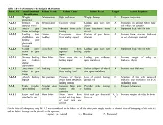
  • 1. Table 1: FMEA Summary of Redesigned TLS System Ident. No. Item/Functional Identification Failure Mode Failure Cause Failure Event Target Action Required A.1.2 Wingtip protection Delamination High peel stress Wingtip damage D Frequent inspection A.2.1.1 Retracts and deploys wheel Stripped gear Excessive torque Landing gear does not deploy A Inspection on ground before take- off or back-up actuator A.2.2.1 Attach gear frame to fuselage Loose bolt Vibration from cyclic loading Frame detachment from aircraft A Implement lock wire for bolts A.2.2.2 Landing load distribution and landing gear placement module Column buckling Compressive stress from landing impact Fracture of gear frame structure A Increase frame structure thickness or use of stronger material A.2.2.3 Mount servo motor to gear frame Loose bolt Vibration from repeated landing impact Landing gear does not deploy A Implement lock wire for bolts A.2.3.1 Secures landing gear position during deployment Shear failure Shear stress due to landing impact Landing gear collapse upon touchdown A Increase margin of safety or thickness of pin A.2.3.2 Attachment of wheel to gear frame Buckling Compressive stress from landing load Sudden collapse of wheel strut upon touchdown A Increase strut thickness A.2.3.2 Absorb landing impact Tire puncture Presence of foreign object debris (FOD) on landing runway Loss of control during ground roll D Selection of tire with increased thickness and inspection for FOD on landing area. A.3.1 Folds propeller upon landing Propeller does not fold Increased hinge joint friction due to corrosion Propeller strike during landing D Frequent lubrication B.1.1.2 keeps roof rack attached to car Shear failure Shear stress from inertial and drag forces of roof rack and aircraft Roof rack gets detached from car A, D, P Increase margin of safety for bolts For the take-off subsystem, only B.1.1.2 was considered as the failure of all the other parts simply results in aborted take-off (stopping of the vehicle) and no further damage on the aircraft or the operator, Legend: A - Aircraft D - Downtime P - Personnel