Sumador de dos bits con cronograma
•Download as DOCX, PDF•
0 likes•518 views

The document summarizes a two-bit adder circuit using flip-flops. It shows the inputs, outputs, and truth tables for SR flip-flops and JK flip-flops used in the adder's design.

Recommended
More Related Content
More from Andrés Mancebo
More from Andrés Mancebo (20)
Recently uploaded
Recently uploaded (20)
Sumador de dos bits con cronograma
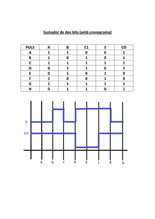
- 1. Sumador de dos bits (amb cronograma) PULS A B C D E F G H A 1 1 1 0 0 1 1 0 B 1 0 1 1 1 0 1 1 C1 0 1 1 1 0 0 1 1 S 0 0 1 0 1 1 1 0 CO 1 1 1 1 0 0 1 1
- 3. Biestable J-K J K Qt Qt + 1 0 0 0 0 0 0 1 1 0 1 0 0 0 1 1 0 1 0 0 1 1 0 1 1 1 1 0 1 1 1 1 0