1. !
C omputer simulation of
Robert S. Ruffini , Robert T. Ruffini , Valentin S. Nemkov , Robert C. Goldstein
induction heating
- Fluxtrol Manufacturing, Centre for Induction Technology..
?
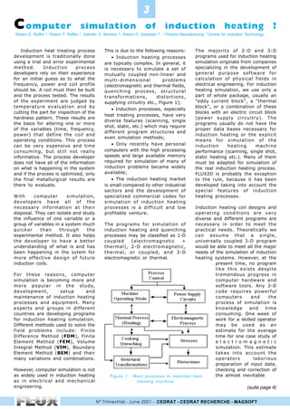
Induction heat treating process This is due to the following reasons: The majority of 2-D and 3-D
development is traditionally done • Induction heating processes programs used for induction heating
using a trial and error experimental are typically complex. In general, it simulation originate from companies
method. Induction process is necessary to simulate a set of specializing in the development of
developers rely on their experience mutually coupled non-linear and general purpose software for
for an initial guess as to what the multi-dimensional problems calculation of physical fields in
frequency, power and coil profile (electromagnetic and thermal fields, electrical engineering. For induction
should be. A coil must then be built quenching process, structural heating simulation, we use only a
and the process tested. The results transformations, distortions, part of whole package, usually an
of the experiment are judged by supplying circuitry etc., Figure 1); eddy current block, a thermal
temperature evaluation and by block, or a combination of these
• Induction processes, especially
cutting the part for inspection of the blocks with an electric circuit block
heat treating processes, have very
hardness pattern. These results are (power supply circuitry). The
diverse features (scanning, single
the basis for altering one or more programs usually do not have the
shot, static, etc.) which may require
of the variables (time, frequency, proper data bases necessary for
different program structures and
power) that define the coil and induction heating or the explicit
even simulation methods;
operating conditions. This process means for simulation of the
can be very expensive and time • Only recently have personal induction heating machine
consuming, but still not really computers with the high processing performance (scanning, single shot,
informative. The process developer speeds and large available memory static heating etc.). Many of them
does not have all of the information required for simulation of many of must be adapted for simulation of
on what is happening in the system induction problems became widely the real induction heating process.
and if the process is optimized, only available; FLUX2D is probably the exception
the final metallurgical results are • The induction heating market to the rule, because it has been
there to evaluate. is small compared to other industrial developed taking into account the
sectors and the development of special features of induction
With computer simulation, specialized commercial codes for heating processes.
developers have all of the simulation of induction heating
necessary information at their processes is a difficult and low Induction heating coil designs and
disposal. They can isolate and study profitable venture. operating conditions are very
the influence of one variable or a diverse and different programs are
group of variables in a system much The programs for simulation of necessary in order to meet the
quicker than through the induction heating and quenching practical needs. Theoretically we
experimental method. It also helps processes may be classified as 1-D can assume that a single,
the developer to have a better coupled (electromagnetic + universally coupled 3-D program
understanding of what is and has thermal), 2-D electromagnetic, would be able to meet all the major
been happening in the sytem for thermal, or coupled, and 3-D needs of the simulation of induction
more effective design of future electromagnetic or thermal. heating systems. However, at the
induction coils. present time, no program
like this exists despite
For these reasons, computer tremendous progress in
simulation is becoming more and computer hardware and
more popular in the study, software tools. Any 3-D
development, setup and code requires powerful
maintenance of induction heating computers and the
processes and equipment. Many process of simulation is
experts and groups in different knowledge and time
countries are developing programs consuming. One week of
for induction heating simulation. work for a skilled operator
Different methods used to solve the may be used as an
field problems include: Finite estimate for the average
Difference Method (FDM), Finite time for one case study of
Element Method (FEM), Volume e l e c t r o m a g n e t i c
Integral Method (VIM), Boundary simulation. This estimate
Element Method (BEM) and their takes into account the
many variations and combinations. operators laborious
preparation of input data,
However, computer simulation is not checking and correction of
as widely used in induction heating Figure 1 : Main processes in induction heat the almost inevitable
as in electrical and mechanical treating machine.
engineering. (suite page 4)
N° Trimestriel - June 2001 - CEDRAT - CEDRAT RECHERCHE - MAGSOFT
2. Computer
simulation of induction heating ?
Robert S. Ruffini , Robert T. Ruffini , Valentin S. Nemkov , Robert C. Goldstein
(suite)
- Fluxtrol Manufacturing, Centre for Induction Technology..
errors or inaccuracies, geometry A) of the fillet is always a problem
and mesh construction, physical in induction heat treating axles.
property and boundary condition This is a result of the flux density in
description, the calculations a cylindrical system being inversely
themself and the analysis of the proportional to the radius and the
results. The complexity of 3-D equivalent coupling gap between
analysis and the required skill of the the coil and the part. The power
user makes a direct 3-D density is proportional to the
optimization of induction heating square of the flux density. Because
processes and systems rather the radius at point B is larger than
difficult. A strategy based on a at point A, the flux and power
hierarchical use of programs is the Figure 2 : Rule of pyramid for density at this point are smaller
most effective. computer simulation of induction given the same coupling gap. The
heating. lower power density leads to a
For most cases, the first stage in The high tech inductor, in many lower temperature in this zone of
the simulation of the induction cases, is made from a solid piece of the fillet area.
heating system should be a 1D copper by CNC machining and it is
coupled program. This allows one difficult and expensive to modify it The coil we used for this study is a
to study the influence of frequency, after it has already been built. single turn coil with Fluxtrol A type
power density, quench type, and Computer simulation plus the concentrator for good efficiency and
time variations on the process. The application of versatile magnetic flux power factor. The means for
ranges of interest can be studied controllers made of magneto- quenchant supply is not shown. The
quickly and effectively. A good dielectric materials provide an minimum required case depth in the
estimate for the heating time, coil effective solution for induction coil fillet is 4 millimeters and the basic
power and coil voltage can be made design. frequency used is 3 kHz. A heating
from the results of the 1-D time below 4 seconds is desired.
simulation. The axle is one of the typical Finally, the minimum temperature
powertrain components that must for austenitization is 790 C and the
The second stage in the simulation be case hardened by induction. The maximum allowable temperature is
may be done using 2-D most difficult section of the axle to 990 C. The minimum possible
electromagnetic or coupled codes. harden is the fillet area due to the coupling gap is 1 mm.
The coil current, tube profile, induced currents not flowing evenly
coupling distance and magnetic flux across the surface resulting in In any style of induction coil, smaller
concentrator type and dimensions reduced heating of the flange area. coupling gaps lead to higher
that provide the required field and In some axles, both the fillet and efficiency. For this study, we use the
power intensity may be determined. the shaft must be hardened. A minimum possible coupling gap at
With this strategy, a 3-D simulation scanning or single-shot process is the flange end of the fillet,
may often be unnecessary or only used for heat treatment. Other approximately 1 mm. The coupling
required for the coil design and axles, where only the fillet area gap increases from there along the
operating condition corrections for must be hardened, are hardened length of the fillet to compensate
the zones where 3-D effects are with a static heating method. In this for the divergence of flux density.
significant. study, we simulate the static Computer simulation of the
heating of the axle fillet area, austenitization stage
This general approach may be called because this is the most difficult of the case hardening
a rule of pyramid. It states that area to heat. process must take
more simple programs must be used into account many
as a basis for the further use of For this study, we
more complicated packages (Figure used the generic
2). Experiments are required only axle fillet area
to verify the material response to shown in Figure 3.
processing and the phenomena not In this Figure,
covered in simulation (Figure 1). In points A and B are
some cases where the material the endpoints of
properties and behavior during heat the zone to be
treatment are well known, h a r d e n e d .
experiments may not be necessary Obtaining the
at all. same temperature
The above analysis is based on the in the flange area Figure 3 : The axle fillet geometr y
authors’ current experience, but we (point B) and the used for the case study.
believe that it reflects well the shaft area (point
simulation situation in general. (suite page 5)
N° Trimestriel - June 2001 - CEDRAT - CEDRAT RECHERCHE - MAGSOFT
3. #
Computer
simulation of induction heating ?
Robert S. Ruffini , Robert T. Ruffini , Valentin S. Nemkov , Robert C. Goldstein
(suite)
- Fluxtrol Manufacturing, Centre for Induction Technology..
features of this system. Axles are gnetic fields lines are very close to- as we would like. Further increase
made of magnetic steel, which loses gether and don’t penetrate far into of the coupling gap in the axle shaft
its magnetic properties at the Curie the part. The number of field lines area (point A) is required.
Point (around 750 C). As is greater near point B than point
temperature changes, not only do A, because the coupling gap is much Besides varying the coupling gap,
the magnetic properties change, but smaller. The result is that the power another opportunity for heat
so do many other properties of the is distributed very close to the sur- pattern control is frequency
material important for simulation face of the part. variation. To study the effect of
(resistivity, thermal conductivity, frequency on the temperature
etc.). This means the problem to be At the end of the heating cycle, the profile, we changed the frequency
simulated is highly non-linear. surface layer of the area to be from 3 kHz to 10 kHz and kept the
treated is non-magnetic. This heating time, coil geometry and
The preliminary stages of the study causes the field lines to penetrate positioning constant. Figure 8
were done using the 1-D program deeper into the part (Figure 4) shows the austenitized area of the
ELTA. Even though this system is providing the power distribution axle fillet using 10 kHz. In this case,
essentially 2-D, a 1-D approach may shown in Figure 5. The resulting with proper heating of the flange
be applied to a set of cross-sections temperature profile shows that the area there is significant
normal to the part surface. For a flange area of the fillet is at a lower underheating and incomplete
single turn coil, the same coil volta- temperature than the shaft end austenitization of the shaft end. This
ge and heat time must be used for (Figure 6). Figure 7 shows the study shows that the higher the
all cross sections. ELTA gave us ini- austenitized area of the fillet with frequency, the greater the influence
tial estimates for the voltage, cou- a 2.86 second heating time using a of the coupling gap on the
pling gap and power required. It frequency of 3 kHz. The hardened temperature profile and the
also verified that with this frequen- area profile is close to the desired hardness pattern can be fine tuned
cy we were able to get the desire one, but it doesnt go quite as far by frequency variation.
hardening depth in the allotted towards the flange area (point B)
time. Of course,
the values of
power, voltage,
and gap variation
are the lowest
estimate for the
variables.
The second stage
in the study was
done using
FLUX2D, a 2-D
coupled electro-
magnetic plus
.
thermal program. Fig.4 : Magnetic field lines at Fig.5 : Power density distribution Fig.6 : Final temperature
This simulation the end of the heat treating in the axle at the end of the heat distribution in the axle fillet
takes into ac- process. treating process, 3kHz. area, 3kHz.
count the non-
linear properties
of the selected
steel. The foun-
dation laid in the
preliminary sta-
ges reduced the
number of itera-
tions using this
more complicated
and time consu-
ming software
package.
At the beginning
of the process, Fig.7 : Austenitized zone of the Fig.8 : Austenitized zone of the Fig.9 : Austenitized zone of the
the entire axle is axle fillet area with concentrator. axle fillet area with concentrator. axle fillet area with concentrator.
magnetic. At this Frequency 3kHz, time2.9sec. Frequency 10kHz, time2.9sec. Frequency 3kHz, time 5.2sec.
stage, the ma- (suite page 6)
N° Trimestriel - June 2001 - CEDRAT - CEDRAT RECHERCHE - MAGSOFT
4. $
Computer
simulation of induction heating ?
Robert S. Ruffini , Robert T. Ruffini , Valentin S. Nemkov , Robert C. Goldstein
(suite)
- Fluxtrol Manufacturing, Centre for Induction Technology..
Application of magnetic flux control was discussed in the The application of magnetic flux
controllers is also important for publication given at GPC ‘98. The controllers improves not only the coil
hardness pattern control. Figure 9 new findings of this study are that efficiency and power factor, but it
shows the austenitized area for the higher the frequency, the extends the hardened area closer
heating under the same conditions greater the influence of the coupling to the flange end of the fillet. New
as for Figure 7, but with the gap on the system. magnetodielectric materials are
concentrator removed. For this now available for magnetic flux
case, the induced power is lower Power Inductor Technology TM is control in induction heating
and the heating time is longer (5.2 based on computer simulation, systems.
seconds). The austenitized zone application of magnetic flux
doesn’t reach nearly as far towards controllers and the most advanced Robert S. Ruffini1, Robert T. Ruffini1,
the flange area of the fillet (Figure coil manufacturing technology. The Valentin S. Nemkov2, Robert C.
8). Also, the depth of the computer simulation study on Goldstein2 -
austenitized zone is less uniform induction heat treating the axle fillet 1
Fluxtrol Manufacturing,
than for the heating with area presented in this paper 2
Centre for Induction Technology.
concentrator, even though the provides valuable guidelines for the
heating time is longer. coil and process design. The study
showed that a frequency variation
These simulations show that both influences not only the case depth,
the concentrator and the frequency but also the distribution along the
influence the austenitization zone axle surface. This effect may be
in the fillet. The influence of used for hardness pattern control.
concentrator on heat pattern
N° Trimestriel - June 2001 - CEDRAT - CEDRAT RECHERCHE - MAGSOFT