1. UPGRADE INSTALLATION NOTICE
Use this procedure to replace the control panel micro-controller chip (PROM) with an upgraded version.
1. Remove all power (battery first, then AC) from the Control Panel.
2. To guard against static discharge damage during the upgrade process, briefly touch a chassis ground
point in the Control Panel cabinet to discharge any static buildup.
Avoid performing this replacement while standing on a carpeted floor. Performing this replacement
on a carpeted floor increases the possibility of static buildup.
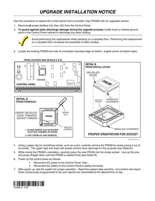
3. Locate the existing PROM and note its orientation (beveled edge at bottom, angled corner at bottom-right).
PROM LOCATION (SEE DETAILS A & B)
DETAIL B
PROM INSTALLATION
BEVELED
EDGE
PRO
CONTROL PANEL M
1 3 4 5 6 7 8 9 10 11 12 13 14 15 16 17 18 19 20 21 22 23 25
DETAIL A SOCKET ANGLED
PROM REMOVAL ARROW CORNER
ORIENT BEVELED PAPER
CLIP
EDGE TOWARDS PROM
SOCKET ARROW
ANGLED
1. PLACE PAPER CLIP IN EITHER CORNER ANGLED CORNER
SLOTTED CORNER OF PROM.
2. PRY PROM UP AND REMOVE. PROPER ORIENTATION FOR SOCKET
PROMUPGRADE-001-V1
4. Using a paper clip (or something similar, such as a pin), carefully remove the PROM by slowly prying it out of
its socket. The upper right and lower left socket corners have openings for this purpose (see Detail A).
5. While noting the PROM’s orientation, carefully place the new PROM into the empty socket. Line up the pins
and press straight down until the PROM is seated firmly (see Detail B).
6. Power up the control panel as follows:
• Reconnect AC power to the Control Panel, then...
• Reconnect the battery to the Control Panel’s battery terminals.
7. After power up, test the system for proper operation. Reset the system date and time, and confirm test report
times (if previously programmed) to be sure reports are transmitted at the desired time of day.
¬.Hl
K4948-5 1/03