SlideShare a Scribd company logo
1 of 11
Sensor/InstrumentSpecificationDefinitions:Range –is the maximumandminimumvalue range over
whicha sensorworkswell.Oftensensorswill workwelloutsidethisrange,butrequire special or
additional calibration.e.g.salinitysensorsdeployedinsalinityof afew PPTin an estuarywhichisbelow
where the PSU scale isdefined(2PSU).However,generallyif youtryto operate asensoroutside its
range,it will notwork(give aconstantoutputat the max,significantlychange sensitivityorgive erratic
results) orbe damagede.g.a 130 m pressure sensordeployedat200 m depth.Accuracy – how well the
sensormeasuresthe environmentinanabsolute sense.Thatishow good the data iswhencompared
witha recognizedstandard.e.g.atemperature sensor accurate to0.001º C isexpectedtoagree within
0.001º C witha temperature standardsuchas a triple-point-of-watercell orthe temperature measured
by a PRT standardizedinrecognizedcalibrationstandardsorbyanothersensorwiththe same accuracy
calibratedproperly.Thisiswhatyouwantto compare resultswithotherobservations.Resolution –the
abilityof a sensortosee small differencesinreadings.e.g.atemperaturesensormayhave aresolution
of 0.000,01º C, butonlybe accurate to 0.001º C. That is youcan believe the sizeof relativesmall
changesintemperature,whichare smallerthanthe accuracyof the sensor.Resolutioninoften
controlledbythe quantizationindigitizingthe signal –e.g.one bitisequal to0.0005º C. Thisisnot a
functionof the sensor,butthe samplingprocess.Repeatability –Thisisthe abilityof a sensortorepeata
measurementwhenputbackinthe same environment.Itisoftendirectlyrelatedtoaccuracy,but a
sensorcan be inaccurate,yetbe repeatable inmakingobservations.Drift –Thisis the low frequency
change in a sensorwithtime.Itisoftenassociatedwithelectronicagingof componentsorreference
standardsinthe sensor.Driftgenerallydecreaseswiththe age of a sensorasthe componentparts
mature.A smoothlydriftingsensorcanbe correctedfordrift.e.g.SeaBird temperature sensorsthatare
driftingabout1 mºC/yr (andhave beensmoothlychangingforseveral years) allow one tocorrectfor the
driftand getmore accurate readings.Driftis alsocausedby biofoulingthatcan’tbe properlycorrected
for,but we oftentry.Hysteresis –A linearupand downinputtoa sensor,resultsinanoutputthat lags
the inpute.g.youget one curve on increasingpressure andanotherondecreasing.Manypressure
sensorshave thisproblem,forbetteronesitcanbe ignored.Itis oftenseeninaCTD whenthe pressure
readingondeckafter recoveryisdifferentfromthe readingbefore itisdeployed.Itisnota problem
withthe response time of the sensor, butisan inherentpropertyof some sensorsthatisundesirable.In
a CTD italsomay be a temperature sensitivityproblem.Stability –isanotherway of statingdrift.That is,
witha giveninputyoualwaysgetthe same output.Drift,shortand longterm stabilityare reallywaysof
expressingasensor’snoise asa functionof frequency.Sometimesthisisexpressedasguaranteed
accuracy over a certaintime period.Driftisoftenaproblemwithpressure sensorsunderhighpressure.
All sensorsdriftwithtime –hence the standardizationof PRTsintriple-point-of-waterandgalliummelt
cells.Response time–a simple estimateof the frequencyresponseof asensorassuminganexponential
behavior.We will discussinmore detailbelow.RefertoSeaBirdtemperature specificationsheets:Self
heating– to measure the resistance inthe thermistortomeasure temperature,we needtoputcurrent
throughit.Currentflowingthrougharesistorcausesdissipationof heatinthe thermistor,whichcauses
it to warmup, or self-heating.Thisisespeciallyimportantintemperature measurement.If the water
velocitychanges,the amountof advectivecoolingwill change,andthe temperature sensedwill change
as a functionof velocity –anemometereffect.Settlingtime –the time forthe sensortoreach a stable
outputonce it isturnedon. Therefore,if youare conservingpowerbyturningoff the sensorsbetween
measurements,youneedtoturnon the powerandwaita certaintime forthe sensorto reacha stable
output.Voltage required –the voltage supplyrange overwhichthe sensorhasa stable output.Toolow
a voltage andthe sensordoesn’tworkproperly,toohighandsomethingburnsout.Currentdrawn –
whatthe sensordrawsat each voltage.Generallythisvariesinverselywithvoltage (the sensordrawsa
nearlyconstantpower- current timesvoltage).Therefore,youneedtosupplyaknownvoltage and
current.If youdo thisfroma battery,beware thatthe voltage decreasesasthe batterydischarges,and
the current rises. Also,the amountof poweryoucanget out of a batterychangeswiththe amount of
currentdrawn.Therefore,whenyoucalculate powerrequirements,youneedtoknow the currentover
the full voltage range togetpowerand batteryrequirements.We willdiscussthisinmore detail laterin
a lab.Output– a voltage range e.g.0 to 5 voltsfor an inputrange of 0 to 30º C,or a frequency
modulatedsine wave,ora square wave of frequencyrange 6 to 12 kHz,etc. Fitof calibrationsto
equation –thermistorsare logdevices,sofitasan inverse polynomialsof logof sensoroutput
(frequency),whichchange fromKtoCelsiusbythe 273.15 SensorNoise Estimation: - Besidesdigitizing
noise,there isanotherlimitationinameasurementdue tothe inherentnoise in asensoritself.Today
we have the technologytoreduce the digitizingintervalordigitizingnoisetobelow the sensornoise,so
the limitingfactorina measurementisgenerallythe physicsof the sensoritself.Ideally,one wouldput
the sensorina noise free environmentandmeasure the spectraof the sensor’soutputtogetthe sensor
noise.However,thiswouldonlyworkif the sensor’snoise wasnotrelatedtosignal level,andif you
couldfinda noise free environment.
DynamicCalibrationsorFrequencyResponse:A sensorisa filterthataffectsthe frequencycontentof
the data that passesthroughit.It isup to the experimentalisttomake sure thatthese filteringeffects
are understoodanddonot affectthe resultsthathe istryingto obtain.To measure the frequency
response function,L(ω),of a sensor,one couldinputanimpulse,measure the response,transformitto
obtainthe frequencyresponsefunction.Animpulse isagoodinputsince itcontainsall frequencies.
Hysteresisof anInductive proximityswitch
The switchinghysteresisof an Inductive proximityswitch describesthe distance betweenthe turn-on
pointwhile approachinganobjectandthe turn-off pointduringthe separationof itfromthe sensor.The
hysteresisbringsaboutastable switchingsignal evenwhenthere are vibrations,temperature drift,or
electrical variations.The hysteresisisdefinedinEN60947-5-2 as a maximum20 % fromthe effective
operatingdistance,andcarriesavalue of typically10 % fromthe effective operatingdistance srforour
sensors.
Hysteresis
The switching hysteresis describes the distance between switching on and switch off. So if there was
a level sensor and you had a high level alarm configured, then the alarm may switch on at 90%, but
in order for the alarm to clear the level would need to fall below (for example) 85%.
Inductive Proximity Sensors
Principles of Operation for Inductive Proximity Sensors
Inductive proximity sensors are designed to operate by generating an electromagnetic field and
detecting the eddy current losses generated when ferrous and nonferrous metal target objects enter
the field. The sensor consists of a coil on a ferrite core, an oscillator, a trigger‐signal level detector
and an output circuit. As a metal object advances into the field, eddy currents are induced in the
target. The result is a loss of energy and a smaller amplitude of oscillation. The detector circuit then
recognizes a specific change in amplitude and generates a signal which will turn the solid‐state output
“ON" or “OFF."
A metal target approaching an inductive proximity sensor (above) absorbs energy generated by the
oscillator. When the target is in close range, the energy drain stops the oscillator and changes the
output state.
Standard Target for Inductive Proximity Sensors
The active face of an inductive proximity switch is the surface where a high‐frequency electro‐
magnetic field emerges.
A standard target is a mild steel square, one mm thick, with side lengths equal to the diameter of the
active face or three times the nominal switching distance, whichever is greater.
Hysteresis (Differential Travel)
The difference between the operate and the release points is called hysteresis or differential travel.
The amount of target travel required for release after operation must be accounted for when selecting
target and sensor locations. Hysteresis is needed to help prevent chattering (turning on and off rapidly)
when the sensor is subjected to shock and vibration or when the target is stationary at the nominal
sensing distance.
Vibration amplitudes must be smaller than the hysteresis band to avoid chatter.
Hysteresis of an Inductive proximity switch
The switching hysteresis of an Inductive proximity switch describes the distance between the turn-on
point while approaching an object and the turn-off point during the separation of it from the sensor.
The hysteresis brings about a stable switching signal even when there are vibrations, temperature
drift, or electrical variations. The hysteresis is defined in EN60947-5-2 as a maximum 20 % from the
effective operating distance, and carries a value of typically 10 % from the effective operating
distance sr for our sensors.
Capacitive Proximity Sensing
Capacitive sensing is a noncontact technology suitable for detecting metals, nonmetals, solids, and
liquids, although it is best suited for nonmetallic targets because of its characteristics and cost relative
to inductive proximity sensors. In most applications with metallic targets, inductive sensing is preferred
because it is both a reliable and a more affordable technology.
Capacitive sensor components
The sensor consists of four basic components:
 A capacitive probe or plate
 An oscillator
 A signal level detector
 A solid-state output switching device
 An adjustment potentiometer
Capacitive proximity sensors are similar in size, shape, and concept to inductive proximity sensors.
However, unlike inductive sensors which use induced magnetic fields to sense objects, capacitive
proximity generate an electrostatic field and reacts to changes in capacitance caused when a target
enters the electrostatic field. When the target is outside the electrostatic field, the oscillator is
inactive. As the target approaches, a capacitive coupling develops between the target and the
capacitive probe. When the capacitance reaches a specified threshold, the oscillator is activated,
triggering the output circuit to switch states between ON and OFF.
Capacitive proximity operation
The ability of the sensor to detect the target is determined by the target’s size, dielectric constant and
distance from the sensor. The larger the target’s size, the stronger the capacitive coupling between
the probe and the target. Materials with higher dielectric constants are easier to detect than those
with lower values. The shorter the distance between target and probe, the stronger the capacitive
coupling between the probe and the target.
Standard Target for Capacitive Proximity Sensors
As with inductive proximity sensors, the standard target for capacitive sensors is a square piece of mild
steel 1 mm (0.04 in.) thick with side lengths equal to the diameter of the active face or three times
the nominal switching distance, whichever is greater. The standard target is grounded per IEC test
standards; however, a target in a typical application does not need to be grounded to achieve reliable
sensing.
Dielectric Constants
Materials with higher dielectric constant values are easier to sense than those with lower values. For
example, water and air are dielectric extremes. A capacitive proximity sensor would be very sensitive
to water, with a dielectric constant of 80, which makes it ideal for applications such as liquid level
sensing. The same sensor, however, would not be sensitive to air, with a dielectric constant of 1. Other
target items would fall within the sensitivity range, such as wet wood, with a dielectric constant
between 10 and 30, and dry wood, between 2 and 6.
A partial listing of dielectric constants for some typical industrial materials follows. For more
information, refer to the CRC Handbook of Chemistry and Physics (CRC Press), the CRC Handbook of
Tables for Applied Engineering Science (CRC Press), or other applicable sources.
Dielectric Constants of Common Industrial Materials
Material Constant Material Constant
Acetone 19.5 Perspex 3.2…3.5
Acrylic Resin 2.7…4.5 Petroleum 2.0…2.2
Air 1.000264 Phenol Resin 4…12
Alcohol 25.8 Polyacetal 3.6…3.7
Ammonia 15…25 Polyamide 5.0
Aniline 6.9 Polyester Resin 2.8…8.1
Aqueous Solutions 50…80 Polyethylene 2.3
Bakelite 3.6 Polypropylene 2.0…2.3
Benzene 2.3 Polystyrene 3.0
Carbon Dioxide 1.000985 Polyvinyl Chloride Resin 2.8…3.1
Carbon Tetrachloride 2.2 Porcelain 4.4…7
Celluloid 3.0 Powdered Milk 3.5…4
Cement Powder 4.0 Press Board 2…5
Cereal 3…5 Quartz Glass 3.7
Chlorine Liquid 2.0 Rubber 2.5…35
Ebonite 2.7…2.9 Salt 6.0
Epoxy Resin 2.5…6 Sand 3-5
Ethanol 24 Shellac 2.5…4.7
Ethylene Glycol 38.7 Shell Lime 1.2
Fired Ash 1.5…1.7 Silicon Varnish 2.8…3.3
Flour 1.5…1.7 Soybean Oil 2.9…3.5
Freon R22 & 502 (liquid) 6.11 Steel
Gasoline 2.2 Styrene Resin 2.3…3.4
Glass 3.7…10 Sugar 3.0
Glycerine 47 Sulphur 3.4
Marble 8.0…8.5 Teflon 2.0
Melamine Resin 4.7…10.2 Toluene 2.3
Metal Transformer Oil 2.2
Mica 5.7…6.7 Turpentine Oil 2.2
Nitrobenzine 36 Urea Resin 5…8
Nylon 4…5 Vaseline 2.2…2.9
Oil Saturated Paper 4.0 Water 80
Paraffin 1.9…2.5 Wood, Dry 2…7
Paper 1.6…2.6 Wood, Wet 10…30
Materials with high dielectric constants may be sensed through the walls of containers made with
materials with lower dielectric constants. An example is the detection of alcohol or flour through a
glass wall. The alcohol would be detected through the glass while the flour would not.
Capacitive sensing through a tank
Each application should be tested. The list of dielectric constants is provided to help determine the
feasibility of an application. The values shown will vary depending on the size and density of the target
material.
Proximity Sensor Hysteresis
In the context of sensors and switches, the term 'hysteresis' refers to the difference between the 'operate'
and 'release' point.
Hysteresis can be demonstrated very easily using a snap-action micro switch. If you carefully and slowly
move the actuator on the switch until you feel it actuate, then reverse direction and slowly release the
actuator until the switch turns off, you'll notice that there's certain amount of travel between the two
points. This difference between the operate and release points is the switch hysteresis. In the case of a
micro switch, it is mechanically controlled, and intentionally built into the design. Hysteresis also exists in
proximity sensors, and it is also an intentional product of the sensor design.
Some hysteresis is necessary in most control systems - the classic example of which is the thermostat
controlling your home furnace. If you set the thermostat to 70°, the furnace might not turn on until the
temperature drops to 68°; and it will stay on until the temperaturereaches, maybe 72°. Without this built-in
hysteresis, the furnace would try to turn on as soon as the temperature dropped below 70°, and turn off
again as soon as 70° was reached. If it operated in such a manner, it would constantly be turning on and off,
wasting energy and requiring much more frequent maintenance.
Proximity sensors' hysteresis prevents them from rapidly turning on and off (chattering) if the target object is
right at the operating threshold point of the sensor. The amount of hysteresis varies with the distance
between the target and the sensor. There is more hysteresis at a greater distance from the sensor
(see Figure 1 below)
Proximity Sensor Hysteresis (Light Blue Shaded Area)
Hysteresis can cause application problems when a too-large proximity sensor is used to detect a small
hole. A proximity sensor's sensing field is shaped like a rounded cone - the sensing field becomes smaller in
diameter as the target-to-sensor distance increases. Some users attempt to take advantageof this fact by
trying to use a large sensor to detect a small hole simply by backing the sensor away from the target. The
theory being that the increased target-to-sensor distance will place the small diameter portion or the sensing
field into the hole, allowing it to be detected.
This method will work if the target approaches the sensor head-on, but if the target approaches the sensor
from the side (as it does in most stamping applications), the hole will not be detected by the sensor unless
the hole diameter is larger than both the sensing area as well as the extended area covered by the 'release'
portion of the hysteresis curve.
This problem can be avoided by selecting a sensor with a sensing field that closely matches (but is slightly
smaller than) the hole diameter, and installing the sensor as close to the target as possible.

More Related Content

What's hot

Colpitts Oscillator
Colpitts OscillatorColpitts Oscillator
Colpitts OscillatorMahadi Hasan
 
Power electronic presentation on LVDT
Power  electronic presentation on LVDT Power  electronic presentation on LVDT
Power electronic presentation on LVDT Eliya Syed
 
Dead time elimination for voltage source inverter
Dead time elimination for voltage source inverterDead time elimination for voltage source inverter
Dead time elimination for voltage source inverternehakardam
 
Harmonic Oscillators
Harmonic OscillatorsHarmonic Oscillators
Harmonic OscillatorsVishal Thakur
 
Electronic Measurement - Q Factor and Q Meter
Electronic Measurement - Q Factor and Q MeterElectronic Measurement - Q Factor and Q Meter
Electronic Measurement - Q Factor and Q MeterBurdwan University
 
Design of DC-DC Converter for SMPS with Multiple isolated outputs.
Design of DC-DC Converter for SMPS with Multiple isolated outputs.Design of DC-DC Converter for SMPS with Multiple isolated outputs.
Design of DC-DC Converter for SMPS with Multiple isolated outputs.Prajwal M B Raj
 
Single phase Transformer
Single phase Transformer  Single phase Transformer
Single phase Transformer johny renoald
 
Switching Voltage Regulator
Switching Voltage RegulatorSwitching Voltage Regulator
Switching Voltage Regulatoribercovich
 
Colpitts Oscillator - Working and Applications
Colpitts Oscillator - Working and ApplicationsColpitts Oscillator - Working and Applications
Colpitts Oscillator - Working and Applicationselprocus
 
single-phase-lab-report
single-phase-lab-reportsingle-phase-lab-report
single-phase-lab-reportMalik Zaid
 

What's hot (20)

Colpitts Oscillator
Colpitts OscillatorColpitts Oscillator
Colpitts Oscillator
 
Power electronic presentation on LVDT
Power  electronic presentation on LVDT Power  electronic presentation on LVDT
Power electronic presentation on LVDT
 
Dead time pwm
Dead time pwmDead time pwm
Dead time pwm
 
Dead time elimination for voltage source inverter
Dead time elimination for voltage source inverterDead time elimination for voltage source inverter
Dead time elimination for voltage source inverter
 
Harmonic Oscillators
Harmonic OscillatorsHarmonic Oscillators
Harmonic Oscillators
 
EMI Unit IV
EMI Unit IVEMI Unit IV
EMI Unit IV
 
Lvdt
LvdtLvdt
Lvdt
 
Electronic Measurement - Q Factor and Q Meter
Electronic Measurement - Q Factor and Q MeterElectronic Measurement - Q Factor and Q Meter
Electronic Measurement - Q Factor and Q Meter
 
Oscillators (1)
Oscillators (1)Oscillators (1)
Oscillators (1)
 
EMI Unit 3 CRO
EMI Unit 3 CROEMI Unit 3 CRO
EMI Unit 3 CRO
 
Design of DC-DC Converter for SMPS with Multiple isolated outputs.
Design of DC-DC Converter for SMPS with Multiple isolated outputs.Design of DC-DC Converter for SMPS with Multiple isolated outputs.
Design of DC-DC Converter for SMPS with Multiple isolated outputs.
 
Single phase Transformer
Single phase Transformer  Single phase Transformer
Single phase Transformer
 
Switching Voltage Regulator
Switching Voltage RegulatorSwitching Voltage Regulator
Switching Voltage Regulator
 
Oscillators
OscillatorsOscillators
Oscillators
 
Oscillator
OscillatorOscillator
Oscillator
 
Colpitts Oscillator - Working and Applications
Colpitts Oscillator - Working and ApplicationsColpitts Oscillator - Working and Applications
Colpitts Oscillator - Working and Applications
 
Oscillators
OscillatorsOscillators
Oscillators
 
Colpitts Oscillator
Colpitts OscillatorColpitts Oscillator
Colpitts Oscillator
 
Oscillators
OscillatorsOscillators
Oscillators
 
single-phase-lab-report
single-phase-lab-reportsingle-phase-lab-report
single-phase-lab-report
 

Similar to PLC

Seminar Report - Capacitive Sensors
Seminar Report - Capacitive SensorsSeminar Report - Capacitive Sensors
Seminar Report - Capacitive SensorsTarun Nekkanti
 
Sensors for Arduino- Shashank M Gowda, YIT, Moodbidri.
Sensors for Arduino- Shashank M Gowda, YIT, Moodbidri.Sensors for Arduino- Shashank M Gowda, YIT, Moodbidri.
Sensors for Arduino- Shashank M Gowda, YIT, Moodbidri.shashu9291
 
Capacitive sensors
Capacitive sensorsCapacitive sensors
Capacitive sensorsYasir Hashmi
 
Energy sensors2 second review
Energy sensors2 second reviewEnergy sensors2 second review
Energy sensors2 second reviewDeep Adhvaryu
 
Tugas Getaran Mekanis (Vibration Sensors)
Tugas Getaran Mekanis (Vibration Sensors)Tugas Getaran Mekanis (Vibration Sensors)
Tugas Getaran Mekanis (Vibration Sensors)Rizki Dewantoro Raharjo
 
sensors basic types, their working principle and applications
sensors basic types, their working principle and applicationssensors basic types, their working principle and applications
sensors basic types, their working principle and applicationsYasir Hashmi
 
Sensors-Interfacing Techniques
Sensors-Interfacing TechniquesSensors-Interfacing Techniques
Sensors-Interfacing TechniquesDr.YNM
 
Sensors-and-Actuators-working principle and types of sensors
Sensors-and-Actuators-working principle and types of sensorsSensors-and-Actuators-working principle and types of sensors
Sensors-and-Actuators-working principle and types of sensorsRameshBabu920476
 
Sensors
SensorsSensors
Sensorsjcraju
 
Sensors for Biomedical Devices and systems
Sensors for Biomedical Devices and systemsSensors for Biomedical Devices and systems
Sensors for Biomedical Devices and systemsGunjan Patel
 
Sensors for Engineering Applications
Sensors for Engineering ApplicationsSensors for Engineering Applications
Sensors for Engineering Applicationsvenkatasuman1983
 

Similar to PLC (20)

Seminar Report - Capacitive Sensors
Seminar Report - Capacitive SensorsSeminar Report - Capacitive Sensors
Seminar Report - Capacitive Sensors
 
unit 2 UPDATED.pptx
unit 2 UPDATED.pptxunit 2 UPDATED.pptx
unit 2 UPDATED.pptx
 
Sensors for Arduino- Shashank M Gowda, YIT, Moodbidri.
Sensors for Arduino- Shashank M Gowda, YIT, Moodbidri.Sensors for Arduino- Shashank M Gowda, YIT, Moodbidri.
Sensors for Arduino- Shashank M Gowda, YIT, Moodbidri.
 
Capacitive sensors
Capacitive sensorsCapacitive sensors
Capacitive sensors
 
Energy sensors2 second review
Energy sensors2 second reviewEnergy sensors2 second review
Energy sensors2 second review
 
UNIT- I.pptx
UNIT- I.pptxUNIT- I.pptx
UNIT- I.pptx
 
Proximity sensors
Proximity sensorsProximity sensors
Proximity sensors
 
Tugas Getaran Mekanis (Vibration Sensors)
Tugas Getaran Mekanis (Vibration Sensors)Tugas Getaran Mekanis (Vibration Sensors)
Tugas Getaran Mekanis (Vibration Sensors)
 
sensors basic types, their working principle and applications
sensors basic types, their working principle and applicationssensors basic types, their working principle and applications
sensors basic types, their working principle and applications
 
3288264.ppt
3288264.ppt3288264.ppt
3288264.ppt
 
Seminar ppt
Seminar pptSeminar ppt
Seminar ppt
 
Sensors-Interfacing Techniques
Sensors-Interfacing TechniquesSensors-Interfacing Techniques
Sensors-Interfacing Techniques
 
Sensors-and-Actuators-working principle and types of sensors
Sensors-and-Actuators-working principle and types of sensorsSensors-and-Actuators-working principle and types of sensors
Sensors-and-Actuators-working principle and types of sensors
 
Sensors
SensorsSensors
Sensors
 
Sensors for Biomedical Devices and systems
Sensors for Biomedical Devices and systemsSensors for Biomedical Devices and systems
Sensors for Biomedical Devices and systems
 
Sensors
SensorsSensors
Sensors
 
Sensors for Engineering Applications
Sensors for Engineering ApplicationsSensors for Engineering Applications
Sensors for Engineering Applications
 
SENSORS_UNIT-2.pdf
SENSORS_UNIT-2.pdfSENSORS_UNIT-2.pdf
SENSORS_UNIT-2.pdf
 
Oscilloscope tutorial
Oscilloscope tutorialOscilloscope tutorial
Oscilloscope tutorial
 
Vibration sensor
Vibration sensorVibration sensor
Vibration sensor
 

Recently uploaded

High Profile Call Girls Nagpur Isha Call 7001035870 Meet With Nagpur Escorts
High Profile Call Girls Nagpur Isha Call 7001035870 Meet With Nagpur EscortsHigh Profile Call Girls Nagpur Isha Call 7001035870 Meet With Nagpur Escorts
High Profile Call Girls Nagpur Isha Call 7001035870 Meet With Nagpur Escortsranjana rawat
 
Model Call Girl in Narela Delhi reach out to us at 🔝8264348440🔝
Model Call Girl in Narela Delhi reach out to us at 🔝8264348440🔝Model Call Girl in Narela Delhi reach out to us at 🔝8264348440🔝
Model Call Girl in Narela Delhi reach out to us at 🔝8264348440🔝soniya singh
 
What are the advantages and disadvantages of membrane structures.pptx
What are the advantages and disadvantages of membrane structures.pptxWhat are the advantages and disadvantages of membrane structures.pptx
What are the advantages and disadvantages of membrane structures.pptxwendy cai
 
GDSC ASEB Gen AI study jams presentation
GDSC ASEB Gen AI study jams presentationGDSC ASEB Gen AI study jams presentation
GDSC ASEB Gen AI study jams presentationGDSCAESB
 
Heart Disease Prediction using machine learning.pptx
Heart Disease Prediction using machine learning.pptxHeart Disease Prediction using machine learning.pptx
Heart Disease Prediction using machine learning.pptxPoojaBan
 
microprocessor 8085 and its interfacing
microprocessor 8085  and its interfacingmicroprocessor 8085  and its interfacing
microprocessor 8085 and its interfacingjaychoudhary37
 
HARMONY IN THE NATURE AND EXISTENCE - Unit-IV
HARMONY IN THE NATURE AND EXISTENCE - Unit-IVHARMONY IN THE NATURE AND EXISTENCE - Unit-IV
HARMONY IN THE NATURE AND EXISTENCE - Unit-IVRajaP95
 
SPICE PARK APR2024 ( 6,793 SPICE Models )
SPICE PARK APR2024 ( 6,793 SPICE Models )SPICE PARK APR2024 ( 6,793 SPICE Models )
SPICE PARK APR2024 ( 6,793 SPICE Models )Tsuyoshi Horigome
 
(ANVI) Koregaon Park Call Girls Just Call 7001035870 [ Cash on Delivery ] Pun...
(ANVI) Koregaon Park Call Girls Just Call 7001035870 [ Cash on Delivery ] Pun...(ANVI) Koregaon Park Call Girls Just Call 7001035870 [ Cash on Delivery ] Pun...
(ANVI) Koregaon Park Call Girls Just Call 7001035870 [ Cash on Delivery ] Pun...ranjana rawat
 
Study on Air-Water & Water-Water Heat Exchange in a Finned Tube Exchanger
Study on Air-Water & Water-Water Heat Exchange in a Finned Tube ExchangerStudy on Air-Water & Water-Water Heat Exchange in a Finned Tube Exchanger
Study on Air-Water & Water-Water Heat Exchange in a Finned Tube ExchangerAnamika Sarkar
 
Gurgaon ✡️9711147426✨Call In girls Gurgaon Sector 51 escort service
Gurgaon ✡️9711147426✨Call In girls Gurgaon Sector 51 escort serviceGurgaon ✡️9711147426✨Call In girls Gurgaon Sector 51 escort service
Gurgaon ✡️9711147426✨Call In girls Gurgaon Sector 51 escort servicejennyeacort
 
Sheet Pile Wall Design and Construction: A Practical Guide for Civil Engineer...
Sheet Pile Wall Design and Construction: A Practical Guide for Civil Engineer...Sheet Pile Wall Design and Construction: A Practical Guide for Civil Engineer...
Sheet Pile Wall Design and Construction: A Practical Guide for Civil Engineer...Dr.Costas Sachpazis
 
Sachpazis Costas: Geotechnical Engineering: A student's Perspective Introduction
Sachpazis Costas: Geotechnical Engineering: A student's Perspective IntroductionSachpazis Costas: Geotechnical Engineering: A student's Perspective Introduction
Sachpazis Costas: Geotechnical Engineering: A student's Perspective IntroductionDr.Costas Sachpazis
 
Call Girls Narol 7397865700 Independent Call Girls
Call Girls Narol 7397865700 Independent Call GirlsCall Girls Narol 7397865700 Independent Call Girls
Call Girls Narol 7397865700 Independent Call Girlsssuser7cb4ff
 
Software and Systems Engineering Standards: Verification and Validation of Sy...
Software and Systems Engineering Standards: Verification and Validation of Sy...Software and Systems Engineering Standards: Verification and Validation of Sy...
Software and Systems Engineering Standards: Verification and Validation of Sy...VICTOR MAESTRE RAMIREZ
 
Oxy acetylene welding presentation note.
Oxy acetylene welding presentation note.Oxy acetylene welding presentation note.
Oxy acetylene welding presentation note.eptoze12
 
Current Transformer Drawing and GTP for MSETCL
Current Transformer Drawing and GTP for MSETCLCurrent Transformer Drawing and GTP for MSETCL
Current Transformer Drawing and GTP for MSETCLDeelipZope
 

Recently uploaded (20)

High Profile Call Girls Nagpur Isha Call 7001035870 Meet With Nagpur Escorts
High Profile Call Girls Nagpur Isha Call 7001035870 Meet With Nagpur EscortsHigh Profile Call Girls Nagpur Isha Call 7001035870 Meet With Nagpur Escorts
High Profile Call Girls Nagpur Isha Call 7001035870 Meet With Nagpur Escorts
 
Model Call Girl in Narela Delhi reach out to us at 🔝8264348440🔝
Model Call Girl in Narela Delhi reach out to us at 🔝8264348440🔝Model Call Girl in Narela Delhi reach out to us at 🔝8264348440🔝
Model Call Girl in Narela Delhi reach out to us at 🔝8264348440🔝
 
What are the advantages and disadvantages of membrane structures.pptx
What are the advantages and disadvantages of membrane structures.pptxWhat are the advantages and disadvantages of membrane structures.pptx
What are the advantages and disadvantages of membrane structures.pptx
 
GDSC ASEB Gen AI study jams presentation
GDSC ASEB Gen AI study jams presentationGDSC ASEB Gen AI study jams presentation
GDSC ASEB Gen AI study jams presentation
 
Heart Disease Prediction using machine learning.pptx
Heart Disease Prediction using machine learning.pptxHeart Disease Prediction using machine learning.pptx
Heart Disease Prediction using machine learning.pptx
 
microprocessor 8085 and its interfacing
microprocessor 8085  and its interfacingmicroprocessor 8085  and its interfacing
microprocessor 8085 and its interfacing
 
HARMONY IN THE NATURE AND EXISTENCE - Unit-IV
HARMONY IN THE NATURE AND EXISTENCE - Unit-IVHARMONY IN THE NATURE AND EXISTENCE - Unit-IV
HARMONY IN THE NATURE AND EXISTENCE - Unit-IV
 
SPICE PARK APR2024 ( 6,793 SPICE Models )
SPICE PARK APR2024 ( 6,793 SPICE Models )SPICE PARK APR2024 ( 6,793 SPICE Models )
SPICE PARK APR2024 ( 6,793 SPICE Models )
 
(ANVI) Koregaon Park Call Girls Just Call 7001035870 [ Cash on Delivery ] Pun...
(ANVI) Koregaon Park Call Girls Just Call 7001035870 [ Cash on Delivery ] Pun...(ANVI) Koregaon Park Call Girls Just Call 7001035870 [ Cash on Delivery ] Pun...
(ANVI) Koregaon Park Call Girls Just Call 7001035870 [ Cash on Delivery ] Pun...
 
Study on Air-Water & Water-Water Heat Exchange in a Finned Tube Exchanger
Study on Air-Water & Water-Water Heat Exchange in a Finned Tube ExchangerStudy on Air-Water & Water-Water Heat Exchange in a Finned Tube Exchanger
Study on Air-Water & Water-Water Heat Exchange in a Finned Tube Exchanger
 
Gurgaon ✡️9711147426✨Call In girls Gurgaon Sector 51 escort service
Gurgaon ✡️9711147426✨Call In girls Gurgaon Sector 51 escort serviceGurgaon ✡️9711147426✨Call In girls Gurgaon Sector 51 escort service
Gurgaon ✡️9711147426✨Call In girls Gurgaon Sector 51 escort service
 
9953056974 Call Girls In South Ex, Escorts (Delhi) NCR.pdf
9953056974 Call Girls In South Ex, Escorts (Delhi) NCR.pdf9953056974 Call Girls In South Ex, Escorts (Delhi) NCR.pdf
9953056974 Call Girls In South Ex, Escorts (Delhi) NCR.pdf
 
Exploring_Network_Security_with_JA3_by_Rakesh Seal.pptx
Exploring_Network_Security_with_JA3_by_Rakesh Seal.pptxExploring_Network_Security_with_JA3_by_Rakesh Seal.pptx
Exploring_Network_Security_with_JA3_by_Rakesh Seal.pptx
 
Sheet Pile Wall Design and Construction: A Practical Guide for Civil Engineer...
Sheet Pile Wall Design and Construction: A Practical Guide for Civil Engineer...Sheet Pile Wall Design and Construction: A Practical Guide for Civil Engineer...
Sheet Pile Wall Design and Construction: A Practical Guide for Civil Engineer...
 
Sachpazis Costas: Geotechnical Engineering: A student's Perspective Introduction
Sachpazis Costas: Geotechnical Engineering: A student's Perspective IntroductionSachpazis Costas: Geotechnical Engineering: A student's Perspective Introduction
Sachpazis Costas: Geotechnical Engineering: A student's Perspective Introduction
 
Call Girls Narol 7397865700 Independent Call Girls
Call Girls Narol 7397865700 Independent Call GirlsCall Girls Narol 7397865700 Independent Call Girls
Call Girls Narol 7397865700 Independent Call Girls
 
Software and Systems Engineering Standards: Verification and Validation of Sy...
Software and Systems Engineering Standards: Verification and Validation of Sy...Software and Systems Engineering Standards: Verification and Validation of Sy...
Software and Systems Engineering Standards: Verification and Validation of Sy...
 
Oxy acetylene welding presentation note.
Oxy acetylene welding presentation note.Oxy acetylene welding presentation note.
Oxy acetylene welding presentation note.
 
Current Transformer Drawing and GTP for MSETCL
Current Transformer Drawing and GTP for MSETCLCurrent Transformer Drawing and GTP for MSETCL
Current Transformer Drawing and GTP for MSETCL
 
🔝9953056974🔝!!-YOUNG call girls in Rajendra Nagar Escort rvice Shot 2000 nigh...
🔝9953056974🔝!!-YOUNG call girls in Rajendra Nagar Escort rvice Shot 2000 nigh...🔝9953056974🔝!!-YOUNG call girls in Rajendra Nagar Escort rvice Shot 2000 nigh...
🔝9953056974🔝!!-YOUNG call girls in Rajendra Nagar Escort rvice Shot 2000 nigh...
 

PLC

  • 1. Sensor/InstrumentSpecificationDefinitions:Range –is the maximumandminimumvalue range over whicha sensorworkswell.Oftensensorswill workwelloutsidethisrange,butrequire special or additional calibration.e.g.salinitysensorsdeployedinsalinityof afew PPTin an estuarywhichisbelow where the PSU scale isdefined(2PSU).However,generallyif youtryto operate asensoroutside its range,it will notwork(give aconstantoutputat the max,significantlychange sensitivityorgive erratic results) orbe damagede.g.a 130 m pressure sensordeployedat200 m depth.Accuracy – how well the sensormeasuresthe environmentinanabsolute sense.Thatishow good the data iswhencompared witha recognizedstandard.e.g.atemperature sensor accurate to0.001º C isexpectedtoagree within 0.001º C witha temperature standardsuchas a triple-point-of-watercell orthe temperature measured by a PRT standardizedinrecognizedcalibrationstandardsorbyanothersensorwiththe same accuracy calibratedproperly.Thisiswhatyouwantto compare resultswithotherobservations.Resolution –the abilityof a sensortosee small differencesinreadings.e.g.atemperaturesensormayhave aresolution of 0.000,01º C, butonlybe accurate to 0.001º C. That is youcan believe the sizeof relativesmall changesintemperature,whichare smallerthanthe accuracyof the sensor.Resolutioninoften controlledbythe quantizationindigitizingthe signal –e.g.one bitisequal to0.0005º C. Thisisnot a functionof the sensor,butthe samplingprocess.Repeatability –Thisisthe abilityof a sensortorepeata measurementwhenputbackinthe same environment.Itisoftendirectlyrelatedtoaccuracy,but a sensorcan be inaccurate,yetbe repeatable inmakingobservations.Drift –Thisis the low frequency change in a sensorwithtime.Itisoftenassociatedwithelectronicagingof componentsorreference standardsinthe sensor.Driftgenerallydecreaseswiththe age of a sensorasthe componentparts mature.A smoothlydriftingsensorcanbe correctedfordrift.e.g.SeaBird temperature sensorsthatare driftingabout1 mºC/yr (andhave beensmoothlychangingforseveral years) allow one tocorrectfor the driftand getmore accurate readings.Driftis alsocausedby biofoulingthatcan’tbe properlycorrected for,but we oftentry.Hysteresis –A linearupand downinputtoa sensor,resultsinanoutputthat lags the inpute.g.youget one curve on increasingpressure andanotherondecreasing.Manypressure sensorshave thisproblem,forbetteronesitcanbe ignored.Itis oftenseeninaCTD whenthe pressure readingondeckafter recoveryisdifferentfromthe readingbefore itisdeployed.Itisnota problem withthe response time of the sensor, butisan inherentpropertyof some sensorsthatisundesirable.In a CTD italsomay be a temperature sensitivityproblem.Stability –isanotherway of statingdrift.That is, witha giveninputyoualwaysgetthe same output.Drift,shortand longterm stabilityare reallywaysof expressingasensor’snoise asa functionof frequency.Sometimesthisisexpressedasguaranteed accuracy over a certaintime period.Driftisoftenaproblemwithpressure sensorsunderhighpressure. All sensorsdriftwithtime –hence the standardizationof PRTsintriple-point-of-waterandgalliummelt cells.Response time–a simple estimateof the frequencyresponseof asensorassuminganexponential behavior.We will discussinmore detailbelow.RefertoSeaBirdtemperature specificationsheets:Self heating– to measure the resistance inthe thermistortomeasure temperature,we needtoputcurrent throughit.Currentflowingthrougharesistorcausesdissipationof heatinthe thermistor,whichcauses it to warmup, or self-heating.Thisisespeciallyimportantintemperature measurement.If the water velocitychanges,the amountof advectivecoolingwill change,andthe temperature sensedwill change as a functionof velocity –anemometereffect.Settlingtime –the time forthe sensortoreach a stable outputonce it isturnedon. Therefore,if youare conservingpowerbyturningoff the sensorsbetween measurements,youneedtoturnon the powerandwaita certaintime forthe sensorto reacha stable output.Voltage required –the voltage supplyrange overwhichthe sensorhasa stable output.Toolow
  • 2. a voltage andthe sensordoesn’tworkproperly,toohighandsomethingburnsout.Currentdrawn – whatthe sensordrawsat each voltage.Generallythisvariesinverselywithvoltage (the sensordrawsa nearlyconstantpower- current timesvoltage).Therefore,youneedtosupplyaknownvoltage and current.If youdo thisfroma battery,beware thatthe voltage decreasesasthe batterydischarges,and the current rises. Also,the amountof poweryoucanget out of a batterychangeswiththe amount of currentdrawn.Therefore,whenyoucalculate powerrequirements,youneedtoknow the currentover the full voltage range togetpowerand batteryrequirements.We willdiscussthisinmore detail laterin a lab.Output– a voltage range e.g.0 to 5 voltsfor an inputrange of 0 to 30º C,or a frequency modulatedsine wave,ora square wave of frequencyrange 6 to 12 kHz,etc. Fitof calibrationsto equation –thermistorsare logdevices,sofitasan inverse polynomialsof logof sensoroutput (frequency),whichchange fromKtoCelsiusbythe 273.15 SensorNoise Estimation: - Besidesdigitizing noise,there isanotherlimitationinameasurementdue tothe inherentnoise in asensoritself.Today we have the technologytoreduce the digitizingintervalordigitizingnoisetobelow the sensornoise,so the limitingfactorina measurementisgenerallythe physicsof the sensoritself.Ideally,one wouldput the sensorina noise free environmentandmeasure the spectraof the sensor’soutputtogetthe sensor noise.However,thiswouldonlyworkif the sensor’snoise wasnotrelatedtosignal level,andif you couldfinda noise free environment. DynamicCalibrationsorFrequencyResponse:A sensorisa filterthataffectsthe frequencycontentof the data that passesthroughit.It isup to the experimentalisttomake sure thatthese filteringeffects are understoodanddonot affectthe resultsthathe istryingto obtain.To measure the frequency response function,L(ω),of a sensor,one couldinputanimpulse,measure the response,transformitto obtainthe frequencyresponsefunction.Animpulse isagoodinputsince itcontainsall frequencies. Hysteresisof anInductive proximityswitch The switchinghysteresisof an Inductive proximityswitch describesthe distance betweenthe turn-on pointwhile approachinganobjectandthe turn-off pointduringthe separationof itfromthe sensor.The hysteresisbringsaboutastable switchingsignal evenwhenthere are vibrations,temperature drift,or electrical variations.The hysteresisisdefinedinEN60947-5-2 as a maximum20 % fromthe effective operatingdistance,andcarriesavalue of typically10 % fromthe effective operatingdistance srforour sensors. Hysteresis The switching hysteresis describes the distance between switching on and switch off. So if there was a level sensor and you had a high level alarm configured, then the alarm may switch on at 90%, but in order for the alarm to clear the level would need to fall below (for example) 85%. Inductive Proximity Sensors Principles of Operation for Inductive Proximity Sensors
  • 3. Inductive proximity sensors are designed to operate by generating an electromagnetic field and detecting the eddy current losses generated when ferrous and nonferrous metal target objects enter the field. The sensor consists of a coil on a ferrite core, an oscillator, a trigger‐signal level detector and an output circuit. As a metal object advances into the field, eddy currents are induced in the target. The result is a loss of energy and a smaller amplitude of oscillation. The detector circuit then recognizes a specific change in amplitude and generates a signal which will turn the solid‐state output “ON" or “OFF." A metal target approaching an inductive proximity sensor (above) absorbs energy generated by the oscillator. When the target is in close range, the energy drain stops the oscillator and changes the output state. Standard Target for Inductive Proximity Sensors
  • 4. The active face of an inductive proximity switch is the surface where a high‐frequency electro‐ magnetic field emerges. A standard target is a mild steel square, one mm thick, with side lengths equal to the diameter of the active face or three times the nominal switching distance, whichever is greater. Hysteresis (Differential Travel) The difference between the operate and the release points is called hysteresis or differential travel. The amount of target travel required for release after operation must be accounted for when selecting target and sensor locations. Hysteresis is needed to help prevent chattering (turning on and off rapidly) when the sensor is subjected to shock and vibration or when the target is stationary at the nominal sensing distance. Vibration amplitudes must be smaller than the hysteresis band to avoid chatter. Hysteresis of an Inductive proximity switch The switching hysteresis of an Inductive proximity switch describes the distance between the turn-on point while approaching an object and the turn-off point during the separation of it from the sensor. The hysteresis brings about a stable switching signal even when there are vibrations, temperature drift, or electrical variations. The hysteresis is defined in EN60947-5-2 as a maximum 20 % from the
  • 5. effective operating distance, and carries a value of typically 10 % from the effective operating distance sr for our sensors. Capacitive Proximity Sensing Capacitive sensing is a noncontact technology suitable for detecting metals, nonmetals, solids, and liquids, although it is best suited for nonmetallic targets because of its characteristics and cost relative to inductive proximity sensors. In most applications with metallic targets, inductive sensing is preferred because it is both a reliable and a more affordable technology. Capacitive sensor components The sensor consists of four basic components:  A capacitive probe or plate  An oscillator  A signal level detector  A solid-state output switching device  An adjustment potentiometer Capacitive proximity sensors are similar in size, shape, and concept to inductive proximity sensors. However, unlike inductive sensors which use induced magnetic fields to sense objects, capacitive proximity generate an electrostatic field and reacts to changes in capacitance caused when a target enters the electrostatic field. When the target is outside the electrostatic field, the oscillator is inactive. As the target approaches, a capacitive coupling develops between the target and the capacitive probe. When the capacitance reaches a specified threshold, the oscillator is activated,
  • 6. triggering the output circuit to switch states between ON and OFF. Capacitive proximity operation The ability of the sensor to detect the target is determined by the target’s size, dielectric constant and distance from the sensor. The larger the target’s size, the stronger the capacitive coupling between the probe and the target. Materials with higher dielectric constants are easier to detect than those with lower values. The shorter the distance between target and probe, the stronger the capacitive coupling between the probe and the target. Standard Target for Capacitive Proximity Sensors As with inductive proximity sensors, the standard target for capacitive sensors is a square piece of mild steel 1 mm (0.04 in.) thick with side lengths equal to the diameter of the active face or three times the nominal switching distance, whichever is greater. The standard target is grounded per IEC test standards; however, a target in a typical application does not need to be grounded to achieve reliable sensing. Dielectric Constants Materials with higher dielectric constant values are easier to sense than those with lower values. For
  • 7. example, water and air are dielectric extremes. A capacitive proximity sensor would be very sensitive to water, with a dielectric constant of 80, which makes it ideal for applications such as liquid level sensing. The same sensor, however, would not be sensitive to air, with a dielectric constant of 1. Other target items would fall within the sensitivity range, such as wet wood, with a dielectric constant between 10 and 30, and dry wood, between 2 and 6. A partial listing of dielectric constants for some typical industrial materials follows. For more information, refer to the CRC Handbook of Chemistry and Physics (CRC Press), the CRC Handbook of Tables for Applied Engineering Science (CRC Press), or other applicable sources. Dielectric Constants of Common Industrial Materials Material Constant Material Constant Acetone 19.5 Perspex 3.2…3.5 Acrylic Resin 2.7…4.5 Petroleum 2.0…2.2 Air 1.000264 Phenol Resin 4…12 Alcohol 25.8 Polyacetal 3.6…3.7 Ammonia 15…25 Polyamide 5.0 Aniline 6.9 Polyester Resin 2.8…8.1 Aqueous Solutions 50…80 Polyethylene 2.3 Bakelite 3.6 Polypropylene 2.0…2.3 Benzene 2.3 Polystyrene 3.0 Carbon Dioxide 1.000985 Polyvinyl Chloride Resin 2.8…3.1 Carbon Tetrachloride 2.2 Porcelain 4.4…7 Celluloid 3.0 Powdered Milk 3.5…4 Cement Powder 4.0 Press Board 2…5 Cereal 3…5 Quartz Glass 3.7 Chlorine Liquid 2.0 Rubber 2.5…35 Ebonite 2.7…2.9 Salt 6.0 Epoxy Resin 2.5…6 Sand 3-5 Ethanol 24 Shellac 2.5…4.7 Ethylene Glycol 38.7 Shell Lime 1.2 Fired Ash 1.5…1.7 Silicon Varnish 2.8…3.3 Flour 1.5…1.7 Soybean Oil 2.9…3.5
  • 8. Freon R22 & 502 (liquid) 6.11 Steel Gasoline 2.2 Styrene Resin 2.3…3.4 Glass 3.7…10 Sugar 3.0 Glycerine 47 Sulphur 3.4 Marble 8.0…8.5 Teflon 2.0 Melamine Resin 4.7…10.2 Toluene 2.3 Metal Transformer Oil 2.2 Mica 5.7…6.7 Turpentine Oil 2.2 Nitrobenzine 36 Urea Resin 5…8 Nylon 4…5 Vaseline 2.2…2.9 Oil Saturated Paper 4.0 Water 80 Paraffin 1.9…2.5 Wood, Dry 2…7 Paper 1.6…2.6 Wood, Wet 10…30 Materials with high dielectric constants may be sensed through the walls of containers made with materials with lower dielectric constants. An example is the detection of alcohol or flour through a glass wall. The alcohol would be detected through the glass while the flour would not. Capacitive sensing through a tank Each application should be tested. The list of dielectric constants is provided to help determine the feasibility of an application. The values shown will vary depending on the size and density of the target material. Proximity Sensor Hysteresis
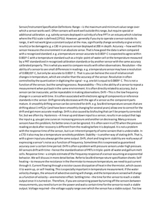
  • 9. In the context of sensors and switches, the term 'hysteresis' refers to the difference between the 'operate' and 'release' point. Hysteresis can be demonstrated very easily using a snap-action micro switch. If you carefully and slowly move the actuator on the switch until you feel it actuate, then reverse direction and slowly release the actuator until the switch turns off, you'll notice that there's certain amount of travel between the two points. This difference between the operate and release points is the switch hysteresis. In the case of a micro switch, it is mechanically controlled, and intentionally built into the design. Hysteresis also exists in proximity sensors, and it is also an intentional product of the sensor design. Some hysteresis is necessary in most control systems - the classic example of which is the thermostat controlling your home furnace. If you set the thermostat to 70°, the furnace might not turn on until the temperature drops to 68°; and it will stay on until the temperaturereaches, maybe 72°. Without this built-in hysteresis, the furnace would try to turn on as soon as the temperature dropped below 70°, and turn off again as soon as 70° was reached. If it operated in such a manner, it would constantly be turning on and off, wasting energy and requiring much more frequent maintenance. Proximity sensors' hysteresis prevents them from rapidly turning on and off (chattering) if the target object is right at the operating threshold point of the sensor. The amount of hysteresis varies with the distance between the target and the sensor. There is more hysteresis at a greater distance from the sensor (see Figure 1 below)
  • 10. Proximity Sensor Hysteresis (Light Blue Shaded Area) Hysteresis can cause application problems when a too-large proximity sensor is used to detect a small hole. A proximity sensor's sensing field is shaped like a rounded cone - the sensing field becomes smaller in diameter as the target-to-sensor distance increases. Some users attempt to take advantageof this fact by trying to use a large sensor to detect a small hole simply by backing the sensor away from the target. The theory being that the increased target-to-sensor distance will place the small diameter portion or the sensing field into the hole, allowing it to be detected. This method will work if the target approaches the sensor head-on, but if the target approaches the sensor from the side (as it does in most stamping applications), the hole will not be detected by the sensor unless the hole diameter is larger than both the sensing area as well as the extended area covered by the 'release' portion of the hysteresis curve.
  • 11. This problem can be avoided by selecting a sensor with a sensing field that closely matches (but is slightly smaller than) the hole diameter, and installing the sensor as close to the target as possible.