The document describes a project to program an Adept iCobra 600 robot to pick up wooden bricks from a conveyor belt and place them in an 'S' shaped pattern. The robot is programmed using Adept ACE software. Coordinates for pick up and placement locations are determined using jog control in LabVIEW. The program was successfully tested and helped students learn basics of industrial robot programming.
Technical data ATN NVM14-3 Monoculars | Optics Trade
iCobra 600 REPORT
1. COMPUTER AIDED AND APPLIED ROBOTICS
Project Title: Programming Adept iCobra 600 Robot
Guide: Dr. Shiakolas, Panayiotis S
Submitted by- Saurabh Deobhankar, UTA id: 1001114694
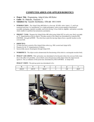
INTRODUCTION: The Adept Cobra 600 Robot is a four-axis SCARA robot. Joints 1, 2, and 4 are
rotational and Joint 3 is translational. It is a high performance robot systemcapable of mechanical
assembly, packaging, material assembly, and screw driving. It has a built-in amplifier and motion controller
which enable it to perform fast and precise automation.
PROJECT TASK: Program the Adept iCobra 600 robot using Adept ACE in such a way that it can make
an ‘S’ shaped pattern of given objects.The place points of the objects are determined by using the JOG
CONTROL through LabVIEW. The robot has to pick the moving objects from a specific location on the
conveyorbelt.
OBJECTIVE:
1. To learn the basic controls of the Adept iCobra robot (e.g. JOG control and Adept ACE).
2. Program for the ‘S’ shaped pattern of objects.
3. Successfully execute the program through Adept ACE.
WORKPIECE: The object used to demonstrate the functioning of the robot is a rectangular wooden brick.
PICK-UP LOCATIONS: Pick up location was determined to be the point where the conveyorbelts stops
due to the effect of a proximity sensorwhich senses the presence ofthe object when the object travels
against it. The co-ordinates of this point were determined by JOG CONTROL in Adept ACE.
PICK-UP POINT: The pick-up point was determined to be-
X Y Z ɼ p r
-242.29 -447.97 386.67 0 180 -48.07
2. PLACING LOCATIONS: The objects were placed so as to form an ‘S’ shaped pattern.
X Y Z ɼ p r
-57.09 532.28 237.4 0 180 46.11
11.79 464.04 263.78 0 180 -39.05
99.57 530.43 262.94 0 180 48.7
184 565.7 269.67 0 180 139.07
260 508.19 267.19 0 180 -136.24
DIFFICULTIES FACED:
Order in which the objects are placed is important. Care should be taken to avoid collision of two objects.
The conveyorand the table are at different heights and hence the height should be adjusted to avoid the
collision of objects with conveyorbelt base.
After picking up one object from the conveyorbelt its height in Z-axis should be increased before
executing the PLACE command to avoid collision with the object following it.