SlideShare a Scribd company logo
1 of 12
Download to read offline
Portfolio I Sandy Ghaly
Project Designer
MS. Arch I Dry Land Design , Urban Policy
sandyeghalli@gmail.com
sandy.ghaly@aridlands.org
Thesis Research I
3 Hydrologic solutions for a water smart LA
Supporting Water-Challenged Communities
Supporting Water-Challenged Communities to Capture and reuse
rain & stormwater by identifying areas suitable for infiltrating
water in the ground with the least investment and the highest
return.
Image: three major hydrologic zones:
Primary Infiltration (Infiltrate here) ,
Secondary Infiltration (Collect & convey) and
Contaminated areas (Do not infiltrate).
Pacoima is a high priority investment because
60% of its soils are suitable for infiltration.
Designing new water systems for low household income communities
that lack open & public spaces might benefit the economy, culture,
park poverty and food access.
Thesis Research I
Coupling infiltration nodes with transit stations
A transit station or stop can serve much more than a transporta-
tion function; it can be a setting for community interaction, a
place that fosters a diversity of activities.
By leveraging multipurpose infrastructural investment transit
stations can become focalpoints in a community, especially if
there is an associated plaza or public space.
Thesis Research I
Place making and food access
3 Hydrologic Solutions for a water smart LA explores the ways
we can maximize the recovery and reuse of rain and storm water
while supporting healthy sustainable food sources and designing
streets that activate public spaces, provide economic revital-
ization, increase public safety, and enhance local culture.
Thesis Research I
Policy Recommendations
Los Angeles needs to redefine the form based code to become a land
development regulation that fosters hydrologic zoning overlays
factors instead of just form or use.
Three distinct hydrologic zones should be incorporated in RE:Code LA:
089
090
088
087
086
085092
084
083
093
082
081
080
094
079
078
077
076
075
095
074
073
007
072
096
071
230
097
229
070
078
069
066
065
098
064
099
062
100
161
162
163
058
057
056
055
054
053
052
051
050
049
048
047
045
044
043
042
041
040
039
015
038
037
171
036
035 034
033
032
031
030
029
029
028
006
001
002
003
004
005
010
011
012
013014
016
017
018
019
021
022
024
025
023
026
027
067
101
102
103
104
105
106
107
108
109
110
111
112
113
114
115
116
117
118
008
009
189
118
119
009
120
122 123
190
124
191
125
126
127
192
128
193
129
130
131
194
132
133
134
135
190
195
121
136
137
138139
196
140
141
197
142
143
144
145
146
147
148
149
150
151
152
153
154
155
156
157
158
159
160
202
3
Academic Work I
Architectural Visualization
A focus on the different drawing techniques:
Projection, intersection and development of points, lines and
planes. Each process had led to a further transformation to create
the final project
089
090
088
087
086
085092
084
083
093
082
081
080
094
079
078
077
076
075
095
074
073
007
072
096
071
230
097
229
070
078
069
066
065
098
064
099
062
100
161
162
163
058
057
056
055
054
053
052
051
050
049
048
047
045
044
043
042
041
040
039
015
038
037
171
036
035 034
033
032
031
030
029
029
028
006
001
002
003
004
005
010
011
012
013014
016
017
018
019
021
022
024
025
023
026
027
067
101
102
103
104
105
106
107
108
109
110
111
112
113
114
115
116
117
118
008
009
189
118
119
009
120
122 123
190
124
191
125
126
127
192
128
193
129
130
131
194
132
133
134
135
190
195
121
136
137
138139
196
140
141
197
142
143
144
145
146
147
148
149
150
151
152
153
154
155
156
157
158
159
160
202
3
03. Method of construction:02. Method of inflection:
The process begins by drawing a line at angle of
the alltitude through each of the points on the object
in the front view. the intersection of these points are
then projected in the top view untill they intersect
with the horizontal base line at each point. the points
are then rotated until they intersect the azimuth.
01. Method of projection :
STEPS:
In order to engage the new volume with the ground
plane and create 3 dimensional habitable object,
mirror the construction lines of the shadows done
previously below the ground plane to re-orient the
new mass in relation to the ground plane.
Using a series of digital modeling techniques that
allow for the translation of three dimensional from two
dimensional lines, a new inhabitable volume is created
thatengages light and projects shadow
Develop prespectival view for the shadow Mirror shodow line to the below surface
The shadow is drawn by connecting the outermost
points on the object when they intersect the ground
and the adjacent Oblique view which illustrates the
shadow projection , connecting the three dimensional
orthographic projection of the original model.
The angles are combined in orthographic projections
to produce a shadow for the model and those lines are
later used after inflecting them to build a model
of habitable pavilions.
D,V
HIN
GE!
A
X
TRUELINE01
O1
U
Y
A
Y,Y'
B
V'U'
Z'
A
TRUELINE02
FRONTVIEW(05)
V
E
Z
D
U
C
SEC08
V
SEC07
ZU
U
SEC06
O2
Z
V1V2
Y
X
31
V
6
SEC05
SEC04
SEC03
SEC01
V4
HORIZONLINE
E
C
7
8910
RL5
D
CUTTINGPLANE(02)
A
Z
B
RL3
B
X
A
D
E
A
O3
C
Z
B
Y
Y
C
D
D
E
E
D
V
Y
U
C
D
22
Y
23
Z
11
21
19
A,Z
20
B,Y
12
13
24
25
26
V4
4
27
CD
D,V
B,Y
28
TOPVIEW(01)
SIDEVIEW(03)
RL2
SE
CTION 01
SE
CTION 02
SE
CTION 03
SE
CTION 04
SE
CTION 05
SE
CTION 06
SE
CTION 07
SE
CTION 08
SE
CTION 09
SE
CTION 10
RL 18NORMAL VIEW
TO
PLANE A,Z,Y,B
6
109
7
29
B,Y
32
18
33
31
Z
A,Z
BASELINE
SEC01
SEC02
E
E,U
38
V3
V2
V1
D
15
34
35
14
40
16
V3
41
17
V2
42
43
C
5
52
39
C
5344
30
51
45
34
46
35
SEC09
47
57,58
54
48
55
CUTTINGPLANE(01)
Y,Y'Z'ZXU
49
SEC10
V
53
RL 20
C
B
5214
11
C,X
13
12
18
E
NORM
ALVIE
W
TO
LI
NE
XE RL21
17
TRUELINE02
RL46
19
A,Z
TRUE
LIN
E01
15
O2
O2
RL41
O3
20
RL44
Zz
Yy
Xx
A
16
D
10
52,53
51
49,50
47,48
44,45
42,43
41
39,40
37,38
36
34,35
32,33
31
29,30
27,28
26
24,25
21
22
A,Z
23
24
25
B,Y
D,V
A,Z
B,Y
RL43
RL45
03
04
02
12,13
14,15
16
11
17,18
19,20
2122,23
54,55
56
57,58
27
TRUELINE03
28
26
D
FOR
IN
FLECTED
PLANE
(02)
RL31
FOR
IN
FLECTED
PLANE
(01)
RL30
32
B
3329
A
E
01
36
NEWC
37
NEWX
A,Z
38
U
D
V
C
C
C
D,V
50
Y
V5
Z
SEC09
04
A
V5
V5
02
42
54
A
43
41
39
40
44
D
45
46
03
B
E
47
57
SIDEVIEW(02)
48
D
58,59
SEC10
3
01
C
NEWC
SEC10
54
V4
C
55
52
B
D,V
C,56
A
2
57,58
49
SEC09
42
V3
45
1
V2
C
51
V1RL04
SEC08
50
48
47
48
D
Y
D
SEC07
PLANEOFPROJECTION
43
A
V3
41
Y,Y'Z'
V2
V
Z
X
40
39
SEC06
U
34
NEWFRONTVIEW
V'
X'
U'
U
35
NEWC
U
V
C
HL1
36
C
37
D
Y,Y'Z'Z
A
X'
X
Z
U'
Y
U
V'
38
E
B
E
E
A
SEC05
E
32
B
E
D
E
C
33
E
V
31
NEWC
RL1
4
30
SEC04
V
SEC03
25
V1
26
27
B
2820
19
STATIONPOINT
B
A
18
21
E
22
D
C
FOR NEW VIEW
RL28
2315
SEC01
SEC02
12
Y,Y'
11
Z'
13
B
17
Y
B,Y
CUTGROUNDPLANE
D
NORMALVIEWOF
NORMALVIEW
TO
CUTTIN
G
PLANE
RL7
C
C,U
VERTEX
A
B
B
V
EC
AB
U
16
VERTEX
C
V'
14
RL61
X'
NORMALVIEW
Z'
Y'
B
ZU
Z'
X'
U'V'
Y'
Z'Y,Y'
D
A
BOTTOMVIEWRL10
Z
CUTTINGPLANE
CUTTINGPLANE
TRUE
LI
NE
01
Xx
CUTTINGPLANE
C
RL6
C
CUTTINGPLANE
NORMAL
VIEW
TO
SE
CTION 01
NORMALVIE
W
TO
PRESEPECTIV
E
VIE
W
RL8
NORMAL
VIEW
TO
SE
CTION
02
RL9
EDGE
VIEW
TO
LINE
DC
NORMAL
VIEW
TO
SE
CTION
03
C
RL10
NORMAL
VIEW
TO
SE
CTION 04
RL11
D
RL12
FRONTVIEWWITHNEWGROUNDPLANE
NORMALVIEW
TO
PLA
NEA,D,V,Z
RL19
X
NO
RM
AL
VIEW
TO
SECTION 06
RL13
NO
RM
AL
VIEW
TO
SE
CTION 07
RL14
NORMAL
VIEW
TO
SE
CTION
08
RL15
NO
RM
AL
VIEW
TO
SECTION 09
RL16
NORMAL
VIEW
TO
SE
CTION 10
RL17
RL60
NORMALVIEW
XUV
A
V
TOPVIEWWITHWALLSPROJECTIONS
C
B
D
B
A
E
D
C
Y
C'
D'V
U
Z
VERTEX
A'
B
B
E
Y'
YZ'
A
V'
D,O2
A
Y
D
U'
Z
TRUE LINE 03
TRUELINE03
TRUE
LIN
E
02
TRUE
LIN
E
02
003
002
RL25
RL24
O2
D
C
001
2
C
1
O2
B
SEC02
D
V
A
Z
B
Y
U
X
22
21
19
20
24
25
26
27
28
Y
11
12
13
29
32
33
SEC03
SEC04
SEC05
18
37
38
36
34
35
SEC06
40
42
43
15
39
SEC07
14
44
45
17
46
B
47
52
53
48
SEC08
3050
50
54
57
58,59
D
NewVertex
NewVertex
A'
A'
C'
D'
E'
Vertex
TopViewofnewModelA,Z
B,Y
D,V
E,U
NewVertex
A
NO
RM
AL
VIEW
TO
SECTION 05
a
C
E
B
VERTEX
VERTEX
VERTEX
VERTEX
C
C
BB
A
A
D
D
51
50
56
b
B,Y
A,Z
C,X
A,Z
B A
D,V
e
Azimu
th
Line
05
Azimu
th
Line
01
Altitude
Line
01
Azimu
th
Line
02
U
Altitude
Line
02
D
B
Azimu
th
Line
04
E
Azimu
th
Line
03
E
C
D
C
A
VY, Y' ZY
Altitude
Line
05
Altitude
Line
04 Altitude
Line
03
Projecting model shadow
Academic Work I
The Super Inflatable
X-LARGE : Professional Work I
The Pearl
The Pearl is an iconic man-made island located on the Arabian Pen-
insula’s eastern shores in Doha, Qatar. Covering an area of 400
hectares, it features 40 km of reclaimed coastline and 20 km of
pristine beaches.
The island is a mixed-use entity of themed districts entailing
beach front villas, elegant town homes, luxury apartments, ex-
clusive penthouses, five star resorts, marinas as well as upscale
retail and restaurants.
Duties include:
- Floor plans developement
- Construction drawings.
- Coordination with different engineering disciplines.
Main Consultant: Smallwood, Reynolds, Stewart, Stewart
Size: 4 million square metres artificial island.
Cost: the initial cost of constructing the island stood at $2.5
billion. It is now believed the project will cost $15 billion upon
completion.
X-LARGE : Professional Work I
Makkah Royal Clock Tower
Jabal Al Qala’a is a residential and hotel superstructure offering world-class
accommodations for visitors and residents of the Holy City of Makkah Al-Mu-
karramah. Often referred to as Makkah’s Royal Clock Tower, Jabal Al Qala’a
majestically stands on a 23 ha prime site south of the Holy Haram within walk-
ing distance from the Haram’s extending outdoor plazas.
Duties include:
- Makkah Royal Clock Tower Hotel design developement.
- Podium facade design and details
- Coordination with different engineering disciplines.
Client: SBG
Main Consultant: AREEN, Bartenbach.
Size: 2.8 million m2 (21.5 million ft2).
Cost: $1.6 billion US dollars
LARGE : Professional Work I
King Saud University for Health Sciences
A state of the art Health Sciences Research and Medical Sciences
University which comprises world class educational, support and
administrative buildings dedicated to health sciences along with
all required service, housing, praying, infrastructure, recre-
ational and sports facilities.
Duties include:
- Science labs design development.
- Facade Construction drawings.
- Coordination with different engineering disciplines.
In collaboration with: Perkins + Will
Size: 1,108,683 (103,000 square meters).
SMALL : Professional Work I
Single family residence
Software used:
AutoCAD - Revit
Photoshop
Thank You !

More Related Content

Similar to Sandy Ghaly Work Samples

Nicholas DiFrank - Professional Portfolio 2015
Nicholas DiFrank - Professional Portfolio 2015Nicholas DiFrank - Professional Portfolio 2015
Nicholas DiFrank - Professional Portfolio 2015Nicholas DiFrank
 
Whitby Feasibility Study final final 555 final final
Whitby Feasibility Study final final 555 final finalWhitby Feasibility Study final final 555 final final
Whitby Feasibility Study final final 555 final finalEdison Mugoya
 
Urban Design Portfolio Tim Hays
Urban Design Portfolio Tim HaysUrban Design Portfolio Tim Hays
Urban Design Portfolio Tim HaysTim Hays
 
Architectural design concept and guidelines for floating structures for tackl...
Architectural design concept and guidelines for floating structures for tackl...Architectural design concept and guidelines for floating structures for tackl...
Architectural design concept and guidelines for floating structures for tackl...IRJET Journal
 
Construction Choreography
Construction ChoreographyConstruction Choreography
Construction ChoreographyMichael Fishman
 
Strategic plan poster final
Strategic plan poster finalStrategic plan poster final
Strategic plan poster finalVanessa Baratta
 
Final Report, Hi7
Final Report, Hi7Final Report, Hi7
Final Report, Hi7Mike White
 
Brownfield project by Shrikant
Brownfield project  by ShrikantBrownfield project  by Shrikant
Brownfield project by ShrikantShriKant49
 
Document Finished
Document FinishedDocument Finished
Document FinishedGregg Boyd
 
Toufic jreije portfolio
Toufic jreije portfolioToufic jreije portfolio
Toufic jreije portfoliotkjreije
 
SY_Yao_Portfolio0615
SY_Yao_Portfolio0615SY_Yao_Portfolio0615
SY_Yao_Portfolio0615Yao Shi-Yuan
 
Portfolio DUNNARQ / Aleph Arquitectura 2015
Portfolio DUNNARQ / Aleph Arquitectura 2015Portfolio DUNNARQ / Aleph Arquitectura 2015
Portfolio DUNNARQ / Aleph Arquitectura 2015John Dunn
 
Gardiner East EA Public Forum 3 (Feb062014) - panels
Gardiner East EA Public Forum 3 (Feb062014) - panelsGardiner East EA Public Forum 3 (Feb062014) - panels
Gardiner East EA Public Forum 3 (Feb062014) - panelsGardinerEast
 
Group 5 presentation finalised
Group 5 presentation finalisedGroup 5 presentation finalised
Group 5 presentation finalisedJamesECole
 
Scp improving urban resilience and housing renewal @ junglighat colony.
Scp   improving urban resilience and housing renewal @ junglighat colony.Scp   improving urban resilience and housing renewal @ junglighat colony.
Scp improving urban resilience and housing renewal @ junglighat colony.ANIRBAN CHOUDHURY
 

Similar to Sandy Ghaly Work Samples (20)

Nicholas DiFrank - Professional Portfolio 2015
Nicholas DiFrank - Professional Portfolio 2015Nicholas DiFrank - Professional Portfolio 2015
Nicholas DiFrank - Professional Portfolio 2015
 
Whitby Feasibility Study final final 555 final final
Whitby Feasibility Study final final 555 final finalWhitby Feasibility Study final final 555 final final
Whitby Feasibility Study final final 555 final final
 
Urban Design Portfolio Tim Hays
Urban Design Portfolio Tim HaysUrban Design Portfolio Tim Hays
Urban Design Portfolio Tim Hays
 
Architectural design concept and guidelines for floating structures for tackl...
Architectural design concept and guidelines for floating structures for tackl...Architectural design concept and guidelines for floating structures for tackl...
Architectural design concept and guidelines for floating structures for tackl...
 
Construction Choreography
Construction ChoreographyConstruction Choreography
Construction Choreography
 
Strategic plan poster final
Strategic plan poster finalStrategic plan poster final
Strategic plan poster final
 
Final Report, Hi7
Final Report, Hi7Final Report, Hi7
Final Report, Hi7
 
Brownfield project by Shrikant
Brownfield project  by ShrikantBrownfield project  by Shrikant
Brownfield project by Shrikant
 
Document Finished
Document FinishedDocument Finished
Document Finished
 
Toufic jreije portfolio
Toufic jreije portfolioToufic jreije portfolio
Toufic jreije portfolio
 
Portfolio
PortfolioPortfolio
Portfolio
 
SY_Yao_Portfolio0615
SY_Yao_Portfolio0615SY_Yao_Portfolio0615
SY_Yao_Portfolio0615
 
Portfolio DUNNARQ / Aleph Arquitectura 2015
Portfolio DUNNARQ / Aleph Arquitectura 2015Portfolio DUNNARQ / Aleph Arquitectura 2015
Portfolio DUNNARQ / Aleph Arquitectura 2015
 
Task 9
Task 9Task 9
Task 9
 
Final project
Final projectFinal project
Final project
 
Portfolio of works final
Portfolio of works finalPortfolio of works final
Portfolio of works final
 
Gardiner East EA Public Forum 3 (Feb062014) - panels
Gardiner East EA Public Forum 3 (Feb062014) - panelsGardiner East EA Public Forum 3 (Feb062014) - panels
Gardiner East EA Public Forum 3 (Feb062014) - panels
 
Group 5 presentation finalised
Group 5 presentation finalisedGroup 5 presentation finalised
Group 5 presentation finalised
 
Scp improving urban resilience and housing renewal @ junglighat colony.
Scp   improving urban resilience and housing renewal @ junglighat colony.Scp   improving urban resilience and housing renewal @ junglighat colony.
Scp improving urban resilience and housing renewal @ junglighat colony.
 
TowerAlDhafra - book3_24Sep2007
TowerAlDhafra - book3_24Sep2007TowerAlDhafra - book3_24Sep2007
TowerAlDhafra - book3_24Sep2007
 

Sandy Ghaly Work Samples

  • 1. Portfolio I Sandy Ghaly Project Designer MS. Arch I Dry Land Design , Urban Policy sandyeghalli@gmail.com sandy.ghaly@aridlands.org
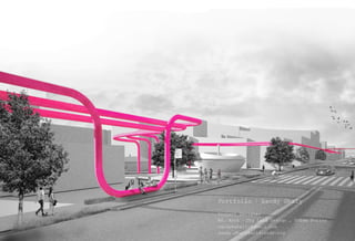
  • 2. Thesis Research I 3 Hydrologic solutions for a water smart LA Supporting Water-Challenged Communities Supporting Water-Challenged Communities to Capture and reuse rain & stormwater by identifying areas suitable for infiltrating water in the ground with the least investment and the highest return. Image: three major hydrologic zones: Primary Infiltration (Infiltrate here) , Secondary Infiltration (Collect & convey) and Contaminated areas (Do not infiltrate). Pacoima is a high priority investment because 60% of its soils are suitable for infiltration. Designing new water systems for low household income communities that lack open & public spaces might benefit the economy, culture, park poverty and food access.
  • 3. Thesis Research I Coupling infiltration nodes with transit stations A transit station or stop can serve much more than a transporta- tion function; it can be a setting for community interaction, a place that fosters a diversity of activities. By leveraging multipurpose infrastructural investment transit stations can become focalpoints in a community, especially if there is an associated plaza or public space.
  • 4. Thesis Research I Place making and food access 3 Hydrologic Solutions for a water smart LA explores the ways we can maximize the recovery and reuse of rain and storm water while supporting healthy sustainable food sources and designing streets that activate public spaces, provide economic revital- ization, increase public safety, and enhance local culture.
  • 5. Thesis Research I Policy Recommendations Los Angeles needs to redefine the form based code to become a land development regulation that fosters hydrologic zoning overlays factors instead of just form or use. Three distinct hydrologic zones should be incorporated in RE:Code LA:
  • 6. 089 090 088 087 086 085092 084 083 093 082 081 080 094 079 078 077 076 075 095 074 073 007 072 096 071 230 097 229 070 078 069 066 065 098 064 099 062 100 161 162 163 058 057 056 055 054 053 052 051 050 049 048 047 045 044 043 042 041 040 039 015 038 037 171 036 035 034 033 032 031 030 029 029 028 006 001 002 003 004 005 010 011 012 013014 016 017 018 019 021 022 024 025 023 026 027 067 101 102 103 104 105 106 107 108 109 110 111 112 113 114 115 116 117 118 008 009 189 118 119 009 120 122 123 190 124 191 125 126 127 192 128 193 129 130 131 194 132 133 134 135 190 195 121 136 137 138139 196 140 141 197 142 143 144 145 146 147 148 149 150 151 152 153 154 155 156 157 158 159 160 202 3 Academic Work I Architectural Visualization A focus on the different drawing techniques: Projection, intersection and development of points, lines and planes. Each process had led to a further transformation to create the final project 089 090 088 087 086 085092 084 083 093 082 081 080 094 079 078 077 076 075 095 074 073 007 072 096 071 230 097 229 070 078 069 066 065 098 064 099 062 100 161 162 163 058 057 056 055 054 053 052 051 050 049 048 047 045 044 043 042 041 040 039 015 038 037 171 036 035 034 033 032 031 030 029 029 028 006 001 002 003 004 005 010 011 012 013014 016 017 018 019 021 022 024 025 023 026 027 067 101 102 103 104 105 106 107 108 109 110 111 112 113 114 115 116 117 118 008 009 189 118 119 009 120 122 123 190 124 191 125 126 127 192 128 193 129 130 131 194 132 133 134 135 190 195 121 136 137 138139 196 140 141 197 142 143 144 145 146 147 148 149 150 151 152 153 154 155 156 157 158 159 160 202 3
  • 7. 03. Method of construction:02. Method of inflection: The process begins by drawing a line at angle of the alltitude through each of the points on the object in the front view. the intersection of these points are then projected in the top view untill they intersect with the horizontal base line at each point. the points are then rotated until they intersect the azimuth. 01. Method of projection : STEPS: In order to engage the new volume with the ground plane and create 3 dimensional habitable object, mirror the construction lines of the shadows done previously below the ground plane to re-orient the new mass in relation to the ground plane. Using a series of digital modeling techniques that allow for the translation of three dimensional from two dimensional lines, a new inhabitable volume is created thatengages light and projects shadow Develop prespectival view for the shadow Mirror shodow line to the below surface The shadow is drawn by connecting the outermost points on the object when they intersect the ground and the adjacent Oblique view which illustrates the shadow projection , connecting the three dimensional orthographic projection of the original model. The angles are combined in orthographic projections to produce a shadow for the model and those lines are later used after inflecting them to build a model of habitable pavilions. D,V HIN GE! A X TRUELINE01 O1 U Y A Y,Y' B V'U' Z' A TRUELINE02 FRONTVIEW(05) V E Z D U C SEC08 V SEC07 ZU U SEC06 O2 Z V1V2 Y X 31 V 6 SEC05 SEC04 SEC03 SEC01 V4 HORIZONLINE E C 7 8910 RL5 D CUTTINGPLANE(02) A Z B RL3 B X A D E A O3 C Z B Y Y C D D E E D V Y U C D 22 Y 23 Z 11 21 19 A,Z 20 B,Y 12 13 24 25 26 V4 4 27 CD D,V B,Y 28 TOPVIEW(01) SIDEVIEW(03) RL2 SE CTION 01 SE CTION 02 SE CTION 03 SE CTION 04 SE CTION 05 SE CTION 06 SE CTION 07 SE CTION 08 SE CTION 09 SE CTION 10 RL 18NORMAL VIEW TO PLANE A,Z,Y,B 6 109 7 29 B,Y 32 18 33 31 Z A,Z BASELINE SEC01 SEC02 E E,U 38 V3 V2 V1 D 15 34 35 14 40 16 V3 41 17 V2 42 43 C 5 52 39 C 5344 30 51 45 34 46 35 SEC09 47 57,58 54 48 55 CUTTINGPLANE(01) Y,Y'Z'ZXU 49 SEC10 V 53 RL 20 C B 5214 11 C,X 13 12 18 E NORM ALVIE W TO LI NE XE RL21 17 TRUELINE02 RL46 19 A,Z TRUE LIN E01 15 O2 O2 RL41 O3 20 RL44 Zz Yy Xx A 16 D 10 52,53 51 49,50 47,48 44,45 42,43 41 39,40 37,38 36 34,35 32,33 31 29,30 27,28 26 24,25 21 22 A,Z 23 24 25 B,Y D,V A,Z B,Y RL43 RL45 03 04 02 12,13 14,15 16 11 17,18 19,20 2122,23 54,55 56 57,58 27 TRUELINE03 28 26 D FOR IN FLECTED PLANE (02) RL31 FOR IN FLECTED PLANE (01) RL30 32 B 3329 A E 01 36 NEWC 37 NEWX A,Z 38 U D V C C C D,V 50 Y V5 Z SEC09 04 A V5 V5 02 42 54 A 43 41 39 40 44 D 45 46 03 B E 47 57 SIDEVIEW(02) 48 D 58,59 SEC10 3 01 C NEWC SEC10 54 V4 C 55 52 B D,V C,56 A 2 57,58 49 SEC09 42 V3 45 1 V2 C 51 V1RL04 SEC08 50 48 47 48 D Y D SEC07 PLANEOFPROJECTION 43 A V3 41 Y,Y'Z' V2 V Z X 40 39 SEC06 U 34 NEWFRONTVIEW V' X' U' U 35 NEWC U V C HL1 36 C 37 D Y,Y'Z'Z A X' X Z U' Y U V' 38 E B E E A SEC05 E 32 B E D E C 33 E V 31 NEWC RL1 4 30 SEC04 V SEC03 25 V1 26 27 B 2820 19 STATIONPOINT B A 18 21 E 22 D C FOR NEW VIEW RL28 2315 SEC01 SEC02 12 Y,Y' 11 Z' 13 B 17 Y B,Y CUTGROUNDPLANE D NORMALVIEWOF NORMALVIEW TO CUTTIN G PLANE RL7 C C,U VERTEX A B B V EC AB U 16 VERTEX C V' 14 RL61 X' NORMALVIEW Z' Y' B ZU Z' X' U'V' Y' Z'Y,Y' D A BOTTOMVIEWRL10 Z CUTTINGPLANE CUTTINGPLANE TRUE LI NE 01 Xx CUTTINGPLANE C RL6 C CUTTINGPLANE NORMAL VIEW TO SE CTION 01 NORMALVIE W TO PRESEPECTIV E VIE W RL8 NORMAL VIEW TO SE CTION 02 RL9 EDGE VIEW TO LINE DC NORMAL VIEW TO SE CTION 03 C RL10 NORMAL VIEW TO SE CTION 04 RL11 D RL12 FRONTVIEWWITHNEWGROUNDPLANE NORMALVIEW TO PLA NEA,D,V,Z RL19 X NO RM AL VIEW TO SECTION 06 RL13 NO RM AL VIEW TO SE CTION 07 RL14 NORMAL VIEW TO SE CTION 08 RL15 NO RM AL VIEW TO SECTION 09 RL16 NORMAL VIEW TO SE CTION 10 RL17 RL60 NORMALVIEW XUV A V TOPVIEWWITHWALLSPROJECTIONS C B D B A E D C Y C' D'V U Z VERTEX A' B B E Y' YZ' A V' D,O2 A Y D U' Z TRUE LINE 03 TRUELINE03 TRUE LIN E 02 TRUE LIN E 02 003 002 RL25 RL24 O2 D C 001 2 C 1 O2 B SEC02 D V A Z B Y U X 22 21 19 20 24 25 26 27 28 Y 11 12 13 29 32 33 SEC03 SEC04 SEC05 18 37 38 36 34 35 SEC06 40 42 43 15 39 SEC07 14 44 45 17 46 B 47 52 53 48 SEC08 3050 50 54 57 58,59 D NewVertex NewVertex A' A' C' D' E' Vertex TopViewofnewModelA,Z B,Y D,V E,U NewVertex A NO RM AL VIEW TO SECTION 05 a C E B VERTEX VERTEX VERTEX VERTEX C C BB A A D D 51 50 56 b B,Y A,Z C,X A,Z B A D,V e Azimu th Line 05 Azimu th Line 01 Altitude Line 01 Azimu th Line 02 U Altitude Line 02 D B Azimu th Line 04 E Azimu th Line 03 E C D C A VY, Y' ZY Altitude Line 05 Altitude Line 04 Altitude Line 03 Projecting model shadow Academic Work I The Super Inflatable
  • 8. X-LARGE : Professional Work I The Pearl The Pearl is an iconic man-made island located on the Arabian Pen- insula’s eastern shores in Doha, Qatar. Covering an area of 400 hectares, it features 40 km of reclaimed coastline and 20 km of pristine beaches. The island is a mixed-use entity of themed districts entailing beach front villas, elegant town homes, luxury apartments, ex- clusive penthouses, five star resorts, marinas as well as upscale retail and restaurants. Duties include: - Floor plans developement - Construction drawings. - Coordination with different engineering disciplines. Main Consultant: Smallwood, Reynolds, Stewart, Stewart Size: 4 million square metres artificial island. Cost: the initial cost of constructing the island stood at $2.5 billion. It is now believed the project will cost $15 billion upon completion.
  • 9. X-LARGE : Professional Work I Makkah Royal Clock Tower Jabal Al Qala’a is a residential and hotel superstructure offering world-class accommodations for visitors and residents of the Holy City of Makkah Al-Mu- karramah. Often referred to as Makkah’s Royal Clock Tower, Jabal Al Qala’a majestically stands on a 23 ha prime site south of the Holy Haram within walk- ing distance from the Haram’s extending outdoor plazas. Duties include: - Makkah Royal Clock Tower Hotel design developement. - Podium facade design and details - Coordination with different engineering disciplines. Client: SBG Main Consultant: AREEN, Bartenbach. Size: 2.8 million m2 (21.5 million ft2). Cost: $1.6 billion US dollars
  • 10. LARGE : Professional Work I King Saud University for Health Sciences A state of the art Health Sciences Research and Medical Sciences University which comprises world class educational, support and administrative buildings dedicated to health sciences along with all required service, housing, praying, infrastructure, recre- ational and sports facilities. Duties include: - Science labs design development. - Facade Construction drawings. - Coordination with different engineering disciplines. In collaboration with: Perkins + Will Size: 1,108,683 (103,000 square meters).
  • 11. SMALL : Professional Work I Single family residence Software used: AutoCAD - Revit Photoshop