3. ACKNOWLEDGEMENT
The project has been prepared based on the vocational training
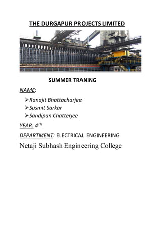
undergone in a highly esteemed organization of Eastern region, a
pioneer in Generation, Transmission & Distribution of power, one of
the most technically advanced & largest thermal power stations in
West Bengal, the Durgapur Project Limited (DPL), Durgapur. We
would like to express our heartfelt gratitude to the authorities of DPL
and Netaji Subhash Engineering College for providing us such an
opportunity to undergo training in the thermal power plant of DPL.
We would also thank its esteemed engineers for the plethora of
knowledge and the experience they have shared with us during the
training period.
We would like to give special thanks to Mr. Sisir Kumar Ghosh and
Anup Kumar Bhattacharaya (training co-ordinator) for giving us the
chance to be a trainee in DPL.
Last but not the least we would like to thank THE ALMIGHTY GOD
without whom this would not have been dreamt of.
4. INTRODUCTION
The DURGAPUR PROJECT LIMITED (DPL) was established in 1958 by
Dr. Bidhan Chandra Roy. It consist of coke oven batteries, by product
plant, and water works. It is under the administrative control of the
Government of West Bengal.
DPL is the first undertaking of the state government which has been
engaged in development of infrastructure for industries and was
given the stature of industries. It has helped in development of
various large, medium and small scale industry in and around
Durgapur.
It produces coke oven gas, supply water and electricity. DPL’s coke
oven complex is India’s largest merchant cookery producing coke of
global quality. The plant has rail and linking with Kolkata, Siliguri and
Dhanbad and sea port at an elevation 73m above sea level.
5. INFRASTRUCTURE
LAND: 1910 acres comprising 1060 acres for plant 850 acres for
township.
RAILWAY NETWORK: separate railway Exchange Yard (DCOP siding)
with railway maintained Weighbridge facility.
POWER PLANT
COKE OVEN
DPL comprises of three coke oven plants and 4.5 meter tall recovery
type Cove Oven Batteries with 400mm along with coal washery and
by-products plant. Present production capacity is 27000M.T. which
can be increased to 40000 M.T with commissioning of 3rd
battery.
Water Works
Originally commissioned with a capacity of MGD in 1960, the water
works was expanded up to a capacity of 41 MSD of water treatment
of DVC for use of company’s plant, township and other industries
and domestic consumers.
Unit No Year of
commissioning
Present capacity Renovated
capacity
I. 10.08.60 30MW Scrap
II. 10.06.60 30MW Scrap
III. 23.06.64 70MW Decommissioned
IV. 29.06.64 70MW Decommissioned
V. 04.07.66 77MW Decommissioned
VI. 01.01.87 110MW 110MW
VII. 01.03.08 300MW 300MW
VIII. 01.10.14 250MW 250MW
6. SUBSTATION
Electrical substation is a part of an electrical generation, transmission
and distribution system. It transfer voltage from high to low or
reverse or perform many other important function. Between the
generation station and consumer, electrical power may flow through
substation at different voltage level.
BUS BAR: A system of electrical conductors in a generating and
receiving station on which power is concentrated for distributor. It is
made up of strip or bar of copper, brass or aluminium that conducts
electricity within a switch board, distribution board, substation,
battery bank etc. Its main purpose is to conduct electricity and not to
function as a structural member. Its cross sectional size depends
upon the maximum amount of current that can be easily carried.
POWER CABLE: It is an assembly of the two or more electrical
conductor, usually held together with an overall sheath. It may be
installed as permanent wiring within building, buried in the ground,
run overhead or exposed.
Cables consist of 3 major components:
1.Conductors
2.Insulator Protective jacket
Construction and material are determined by 3 main factor:
1. Working voltage- determine the thickness of insulation.
2. Current carrying capacity- determine the cross sectional size of
the conductor
3. Environmental condition such as temperature, water, chemical
or sunlight exposure and mechanical impact- determine the
form and composition of the outer cable jacket.
For circuit operating at or above 2000v between conductors, a
conductive shield may surround each insulated conductor.
7. ESSENTIAL EQUIPMENTS IN POWER GENERATION
The main equipment of a power plant are
1. Steam generating equipment
2. Condensing equipment
3. Feed water heater
4. Prime mover or turbine
5. Alternator
6. Spray pond and cooling towers.
7. Control room
8. Protecting equipment
9. Switch yard
STEAM POWER PLANT WORKING OF
Steam power plant basically operates on the Rankine cycle. Coal is
burnt in a boiler, which converted water into steam. The steam is
expanded in a turbine, which produces mechanical power driving the
alternator coupled to the turbine. The steam after expansion in
turbine is usually condensed in a condenser to be fed into the boiler
again. In practice, a large number of modification and improvements
have been made so as to improve the thermal efficiency of the plant.
The working of a modern steam power plant can be divided
into 4 main ckt namely-
8. 1. Fuel and Ash ckt-
In DPL, coal is delivered from the supply point to storage site by road.
Then the coal is taken into the boiler bunker from where it falls into
the hopper by gravity and finally requisite quantity of coal falls into
grate by directly or coal spreader.
2. Air and fuel Gas Circuit
Air is taken from atmosphere by forced draught fan or induced
draught fan through air pre -heater, and flue passing to chimney and
then admitted to the furnace. Finally, exhausted to the atmosphere
through chimney.
3. Feed Water and Steam Circuit
The steam coming out of turbine is condensed and condensate is
extracted from condenser by extraction pump and is forced to the
low pressure feed water to raised the temperature. The feed water is
now pumped through deaerator. The feed water is then pumped into
boiler through the economizer in which it is further heated by the
heat of flue gas.
4. Cooling Water Circuit
Cooling water is supplied from river or cooling tower through screen
to remove the matter that might choke the condenser tube. It is
circulated through the condenser for condensing the steam and
finally discharge to the suitable position and in maintaining inflow
pressure.
9. STEAM GENERATINGEQUIPMENT OF POWER PLANT
Steam power plant consist of boiler for production of steam and
other auxiliary equipment for the utilisation of fuel gas.
BOILER---
Boiler is a major equipment of steam power plant. In a boiler ,we
burn coal to produce heat energy which will make the water to
superheated steam. Here 2 type boilers are used namely- fire tube
and water tube boiler. From boiler, steam passes to superheater,
economiser, air pre –heater and then passes through the chimney to
the atmosphere.
In DPL, there are 6 boiler. Here is the boilers are unit wise description
Descriptio
n
Unit1 Unit2 Unit3 Unit4 Unit5 Unit
6
Boiler
make
Babcoc
k &
Wilcox,
UK
Babcoc
k &
Wilcox,
UK
Babcoc
k &
Wilcox,
UK
Babcoc
k &
Wilcox,
UK
Mitsubish
i
ABL
Coal(MT/D
)
504 504 1260 1260 1293 1848
BOILER
A boiler furnace is chamber in which fuel is burnt to liberate the heat
energy and it provides support and enclosures for burners. Its walls
are made of refactory materials is such as fire clay, silica kaolin etc.
10. SUPERHEATER
A superheater is a device which remove the last traces of moisture
from the steam leaving the boiler tube and also increase its
temperature above the saturation temp. It provides two principal
benefits firstly, the overall efficiency is increase, secondly, too much
condensation in the last stages is avoided .The superheater steam is
fed to turbine through the main valve.
ECONOMISER-
It is basically a heat changer by which the temperature of feed water,
coming from high pressure heater is increased to the saturation
temperature or slightly less than the saturation temperature
corresponding to the drum pressure. The feed water is fed to
economizer before supplying to the boiler. Economiser raises boiler
efficiency 10%-12%.
AIR PREHEATER-
An air pre heater increase temperature of air supplied for coal
burning by driving heat from flue gasses. Air is drawn from the
atmosphere by a force draught fan and is passing through air pre
heater supplying to the boiler furnace. The air pre heater extracts
heat from flue gas. The principle benefits of heating the air increased
1% boiler efficiency and increased steam capacity per sq. Meter
boiler surface.
DIFFERENT TYPES FAN FOR BOILER HOUSE-
A fan can be defined as a volumetric machine which like pump
moves quantities of air & gas from one place to another. In doing so
it overcomes resistance to flow by supplying the fluid with the
energy necessary for contained motion.
11. 1) Forced Draught Fan-
To take air from atmosphere at ambient temperature to supply
essentially all the combustion air can either be sized to overcome all
the boiler losses or put the air in furnace.
2) Induced Draught Fan-
Used only in balanced draught unit to suck the gases out of furnace
& through them into the stack. Handle fly ash laden gasses at
temperature of 125-200. Speed seldom exceed 1000 r.p.m.
3) Primary Air Fan-
Used for pulverized system usually sized for 1500 r.p.m. due to high
pressure.
4) Seal Air Fan-
Used to seal mill bearing, coal feeders, and coal pipes in case of
pressure type mill. Speed depends on the types of arrangements of
fan.
5) Ignite Air Fan-
Used to provide necessary combustion air to the ignite control
damper is provided on the discharge which modulates to maintain a
constant differential pressure across ignite when any ignite is in
service. Typical speed 1460 rpm.
6) Scanner Air Fan-
Used to provide necessary cooling air to the flame scanners. Typical
speed 3000 rpm.
12. INDUCED DRAUGHT FAN-
RATED POWER 671.4K/W900 HP
REVOLUTION PER MINTUE 740
FREQUENCY(HZ) PHASE 50,3
RATED VOLTAGE(VOLT) 6600
RATED CURRENT(AMP) 74
RATING MCR
INSULATION CLASS F
DUTY SI, GD(MOTOR)
ALT 1000M
AMBIENT TEMPERATURE 50
MANUFACTURED BY CROMPTION GREAVES
FORCED DRAUGHT FAN-
RATED CURRENT(AMP) 43
RATED VOLTAGE(VOLT) 6600
RATED POWER,PHASE 375KW/500HP,3
REVOLUTION PER MINTUE 988
POWER FACTOR .8
MANUFACTURED BY BHEL
13. ELOCTROSTATIC PRECIPITATOR (E.S.P)
There is various gas cleaning device. Among them plate type of
electrostatic precipitator is useful as it gave 99% efficiency. Its
principle component is two sets of electrodes insulated from each
other. The first set is composed of rows of electrically grounded
vertically grounded plate called collecting electrodes between which
are dust laden gas in flows. The second set of electrodes consist of
wires, called the discharge or emitting electrodes that are centrally
locked, each pare parallel plated. The ash particles are collected in
the electrodes & get separated from ash hopper.
SPECIFICATION OF ESP-
NO OF EMITTERPLATE(-)VE 6*10
NO OF COLLECTER PLATE(+)VE 4*6
NO OF TRANSFORMER 6*1
TRAFORECTIFIER SET
SL NO 11427A
TYPE OTHA43/80
DC VOLT(KV) 43
CURRENT(AMPS),PHASE 8,1
AC I/P VOLTAGE(V),CURRENT(A) 360,157
AC O/P VOLTAGE(V),CURRENT(A) 49.45,1.148
RATED VOLTAGE AMPS(KVA) 56.77
MANUFACTURED BY HINLAND RECTIFIED LIMITED
14. CONDENSATE STSTEM-A typical condensate system consist of the
following-
1. Condenser (including hot well)
2. Condensate pumps
3. Air Extraction
4. Gland coolers & L.P heater system
5. Desecrators
Condenser-
Steam after expansion through the prime mover, goes through the
condenser which condenses the exhaust steam while passing
through them. It provide lowest economic heat rejection temp for
the steam. Condenser are two type-
1) Jet or contact condenser
2) Surface condenser.
EVAPORATOR-
Evaporator are used for supplying pure water as make up feed water
in steam power plant. In an evaporator raw water is evaporated by
using extracted steam & vapours. These vapours can be condensed
in feed water heaters the feed water.
FEED WATER HEATER-
The steam coming out of turbine is condensed and the condensate is
feedback to the boiler as feed water. These heaters are used to heat
the feed water by means of bled steam before it is supplied to the
boiler.
15. BOILER FEED PUMP-
RATED POWER(KW) 4000
REVOLUTION PER
MINUTE
2986
FREQUENCE(HZ),PHASE 50,03
STATOR 66000,400
INSULATION CLASS B
ROTOR SQURREL CAGE
EFFICIENCY (%) 96.6
POWER FACTOR .914
TOTAL WEIGHT(KG) 22000
MANUFACTURED BY BHEL
ELECTRIC OIL HEATER-
TYPE INDIRECT
SERIAL NO 1-84-60-091
NO OF ELEMENTS 80
POWER 60
RATED VOLTAGE(VOLT) 440
PHASE 03
MANUFACTURED BY PENNWALT INDOAT LIMITED
16. COAL MILL-
A pulverized coal fire boiler is industrial or utility boiler that
generates thermal energy by burning pulverized coal. This type boiler
dominates the electrical power industry, providing steam to drive
large turbines. Pulverized coal provides the thermal energy which
produces about 50% of the world electric supply.
Raw coal is fed through a central coal inlet at the top of the
pulverized and falls by gravity to the rotating grinding table mixing
with classifier rejects return regrinding centrifugal action force the
coal outward to the grinding ring where it is pulverized between the
ring & three grinding rollers. Grinding load transmitted from the
tension rods through the loading frame to the road assemble; hold
the rollers in contact with the grinding ring the roller adjust vertically
as a depth of the coal load increase or decrease.
COOLING TOWER-
In modern fossil fuel steam power plant, about 10%-15% of the heat
input rejected to the atmosphere through the boiler chimney, while
48%-52% of heat input is rejected to cooling water system through
the steam condensers. The circulator water takes up the heat of the
exhaust steam & itself become hot. A cooling tower is a wooden or
metallic rectangular structure inside of which is packed with baffling
devices. The hot water is led to the tower top & falls down through
the tower & broken into small particles while passing over the
baffling devices. Air enters the tower from the bottom & flows
upward.
17. POWER GENERATING EQUIPMENTS
TURBINE-
The turbine converts the stored energy in steam into rotational
mechanical energy. The operation of a steam turbine is based upon
the principle that the steam issuing from a small opening attains a
high velocity. The basic construction of a steam turbine is simple.
Steam turbine give high speed(standard speed are 3000rpm &
1500rpm).Maximum size(1000MW), minimum floor space, bulk &
weight, maximum efficiency in large, suitability for highest steam
pressure & temperature steam turbine consists of a rotor resting on
bearing & enclosed in a cylindrical casting. The rotor is turned by
steam limping against attached vanes blades on which it exerts a
force in the tangential direction. Thus a steam turbine could be
viewed as a complex series of wind mill like arrangements; all
assemble on the same shaft. Here three types of turbine are used-
1) High pressure turbine(HP)
2) Intermediate pressure turbine(IP)
3) Low pressure turbine(LP)
ALTERNATORS
A.C generators are usually called alternators. They are also called
synchronous generator. Rotating machines that rotates at a speed
fixed by the supplying frequency & the number of poles are called
synchronous machine
18. Construction
Similar to the other rotating machine, an alternator consist of two
main parts namely, the stator & rotor. The stator is the stationary
part of the machine. It carries the armature winding in which the
voltage is generated. The output of the machine is taken from stator.
The rotor is the rotating part of the machine. The rotor produces the
main field flux.
1. Stator construction- the various part of the stator include the
frame, stator core, stator winding and stator cooling
arrangement. The frame may be of cast iron for small size
machine and welded steel type for large type machines. In
order to reduce hysteresis and eddy current losses the stator
core is assembled with high grade silicon content steel
lamination.
2. Rotor construction- there are two type of rotor namely salient
pole type and cylindrical pole type.
a) Salient pole rotor- The term salient pole means projection, thus
salient pole rotor consist of pole projection out of the surface of the
rotor core. It have large number of poles and operating at lower
speed.
b) Cylindrical rotor- Its rotor construction form a smooth cylinder. It
generally has two or four poles. These rotor turbines are driven by
gas or steam turbine also called turbo generator. Its runs at high
speed and its rating varies from 10MVA to 1500MVA.
19. EXCITATION SYSTEM FOR ALTERNATOR
Excitation means production of flux by passing current in the field
winding. In these plant there are two types of system used for
excitation
1) D.C system- Direct current is required to excite the field
winding of the rotor of the synchronous machine. D.C is
supplied to the rotor field by a dc generator called exciter.
Smaller dc generator called pilot exciter. The main and the pilot
exciter are mounted on the main shaft of the alternator.
2) A.C System- There are two types of exciter system. Rotating
system; this has a high frequency excitation system, permanent
magnet pilot exciter and uncontrolled rectifier.
COOLING SYSTEM: In this plant cooling was done in 1 & 2 unit by air.
Thus closed circuit air cooled generator has shaft mounted fan and
horizontal water cool air copular are mounted in the hot duct. In
case of unit 3, 4 and 5 hydrogen cooling is done.
SPECIFICATION OF ALTERNATOR
Unit no 1&2 Alternator
RATED VOLTAGE 1100+-7.5%
RATED CURRENT 3440A
BASE MVA 37.5 MVA
PHASE 3
SPEED 3000RPM
FREQUENCY 50HZ
POWER FACTOR 0.8
EXCITAION 205VOLT,408 Amp
CONNECTION YY
MANUFACTURED BY ENGLISH ELECTRIC
Unit no 3,4&5 Alternator
20. RATED VOLTAGE 1100+-7.5%
RATED CURRENT 4650/4600/4330/3940A
BASE MVA 88.5/87.5/82.5/75.2 MVA
PHASE 3
SPEED 3000RPM
FREQUENCY 50HZ
POWER FACTOR 0.87/0.88/0.9
EXCITAION 381/372/384/366VOLT,665/650/670/640Amp
CONNECTION YY
FOR H2 COOLING 1.05/1.05/0.5/0.65 KG/cm2
MANUFACTURED BY SIMENS
TYPE
RATING
HYGROGEN PRESSURE
APARENT OUTPUT
ACTIVE OUTPUT
RATED VOLTAGE 1100
RATED CURRENT 220
SPEED 3000RPM
FREQUENCY 50HZ
POWER FACTOR 0.8LAG
GENERATOR TERMINAL 6
CONNECTION YY
MANUFACTURED BY SIMENS
SILICON RECTIFIER POWER UNIT:
TRANSFORMER RECTIFIER
VOLT AMP
RATING(KVA)
16 CONNECTION SINGLE PHASE
OPEN BRIDE
CONNECTION
FREQUENCY(HZ) 50 PEAK DC
VOLTAGE(V)
70000
PHASE 01 AVERADE DC 0.23
21. TEMPERATURE
LOW VOLTAGE SIDE(V) 380 AMBIENT
TEMPERATURE
60C
CURRENT(AMP) 53300 WEIGHT OF THE
CASE AND
FITTING
680 KG
HIGH VOLTAGE SIDE(V) 42.1 WEIGHT OF OIL 580 LTR
CURRENT(AMPS) 0.3 TOTAL WEIGHT 1550KG
% IMPEDENCE 5.79 MANUFACTURED
BY BHEL
WEIGHT OF
TRANSFORMER
430
COKE OVEN PLANT
DPL’s Coke Oven Complex is India’s one of the largest Merchant
Cokery producing Coke of global quality. The current installed
capacity of the Coke Oven Complex is 0.5 million tons of Gross Coke
per annum, 20000 tons of Crude Coal Tar per annum & million NM3
of Coke Oven gas per annum.
The DPL plant has Rail/Highway/Road linkages to cities of Kolkata,
Siliguri, Dhanbad & Delhi & sea port at Haldia.
The fuel used in this plant is coal. Here low grade bituminous coal
low grade bituminous (calorific value – 6000 Kcal/Kg) is used. This
coal is converted into coke by undergoing different process with the
help of different types of 3 phase ac motors.
AC MOTOR:
An AC motor is an electric driven by an alternating current (AC). It
commonly consist of 2 basic parts,
1. STATOR – Having coils supplied with alternating current to
produce a rotating magnetic field. The parts of stator are –
22. A.STATOR FRAME
B.STATOR CORE
C.STATOR WINDING
2.ROTOR – attached to the o/p shaft i.e given a torque by the
rotating field. In rotor has –
A. ROTOR WINDING
TYPES OF AC MOTORS:
1. Squirrel cage motor: In overall shape it is a cylinder mounted
on a shaft. Internally it contains longitudinal bars set into grooves
& connected at both ends by shorting rings forming cage like
shape.
2. Slip ring motor: A wound rotor motor is a type of inductive
motor where the rotor winding are connected through slip ring to
external resistances. Adjusting the resistance allows control of
speed-torque characteristics of the motor. Wound -rotor motor
can be started with low inrush current.
VARIOUS PARTS OF AC MOTOR:
1. Body with stator winding
2. End shield drive end
3. Bearing washer
4. Preloading washer
5. Deep groove ball bearing
6. Inner bearing cover
7. End shield non drive
8. Rotor
9. Terminal box cover
10. Rubber packing
11. Terminal block assembly
23. 12. Terminal box
13. Conduit plug
14. Fan
15. Circlip
16. Fan cowl
17. Feather key for transmission element
18. Feather key for fan
19. Eye bold
20. Connecting link
MAINTAINANCE OF INDUCTION MOTOR:
1. The bearings are pre lubricated and maintenance free.
Operating condition permitting, unsealed bearings should be
cleaned at intervals of about 10000 operation hours with
trichloroethylene or clean petrol.
2. Balmer Lawrie LL3 and Shell-MP3 are recommended for use in
motors. Mixing of grease should be avoided.
3. When the motor is opened, protect bearing from foreign
particles and dirt by wrapping then with clean paper or
polythene sheath.
4. During reassembly of motor ensure that wavy washer and brass
washer are kept in their position and bearing cover are secured
properly. This washer are esp. Designed to provide adequate
preloading on the bearing.
5. Clean the entire path of the cooling air on the motor at regular
intervals.
6. The temp of the motor judge by hand filling could be
misleading in the case of overheating, the actual temp should
measure with the thermometer and should be compared with
the permissible temperature rise according to the temp class of
the motors.
7. Overheating of the motor may be due to overloading of the
motor, too low or too high voltages, frequency, fluctuations
24. over greasing of bearing, foreign materials in the air gap
between stator and rotor necessary corrective action is to be
taken accordingly.
8. When order in spare parts, state the motor type , machine
chamber, type of construction as shown in the rating plate,
parts description given in the part list and no of unit required.
INSTALLATION AND MOUNTING OF MOTORS:
1. See that the motor rotates freely by turning the shaft by hand.
2. Replace the grease charge of bearing if the motor has been
stored for longer than 18 months.
3. Check the insulation resistance by applying a dc voltage of
500V, if it is low due to moisture dry out the stator winding till
the insulation resistance increase above 1MOHMS by any of the
accepted method
4. Remove anti-corrosion coating on the shaft with petrol white
spirit or kerosene, do not scrap the coating,
5. See that the machine surface of the motor fit and also the
surface on which the motor is mounted is clean and perfectly in
level.
6. The coupling parts to be fitted on the motor shaft are to be
properly to be balanced. The bore and keyway are to be
machine accurately. The recommended tolerance for the bore
diameter is H7.
7. The coupling part or pulley must be carefully fitted but means
ESP. Tackle for which a tapped hole is provided at shaft end.
Blow must be avoided since they might damage bearing. The
tackle can also be used for removal of coupling.
8. While using non flexible coupling it should be noted the shaft of
the motor or the driven machine must be in perfect alignment
and axis should coincides in accurate alignment result in stress
on bearing and noise running
25. 9. See the screw for fixing the motor to the foundation are
secured properly.
TYPE OF MOTOR USED IN COKE OVEN SECTION
1. PUSHER CAR
a. LT Motor
Power rating-20kw
Fill load current-42 amp
RPM-960
Motor type-slip ring motor
b. PUSHER motor
Power rating-80kw
RPM -960
Motor type –slip ring motor
c. LEVELER motor
Power rating -20kw
Full load current 42 amp
RPM -960
Motor type –slip ring motor
d. DOORETER motor
Power rating 5.5kw
Full load current -12 amp
RPM- 960
Motor type- squirrel cage motor
e. LIFTING motor
Power rating -2.2kw
Motor type –squirrel cage motor
f. LATCH motor
Power rating -2.2kw
26. Motor type –squirrel cage motor
2. QUENCHING CAR MOTOR
a) LT motor
Power rating-80 KW
RPM-755
Motor type –slip ring motor
b) COMPOSSER
Power rating-18.5kw
Full load current-33amp
RPM-1400
3.CHARGINGCAR
a.LT motor
Power rating-15.3kw
Full load current-33amp
RPM-755
Motor type- slip ring motor
b.TABLE motor
Power rating-11kw
Full load current-23amp
RPM-755
Motor type-squirrel cage motor
27. GENERATOR RATINGSPECIFICATION
UNIT 1
PRIMARY EXCITER
SERIAL NUMBER :NO M25868 TGV
101/7
RATED VOLTAGE :110 VOLTS
RATED CURRENT :36 AMPS
POWER RATING OPERATION :4KW(FOR CONTINOUS)
SPEED:3000RPM
TYPE OF EXCITATION :SELF EXCITED
MIN. OPERATION VOLTAGE :110 VOLTS
MIN. OPERATION CURRENT :1.6 AMPS
MANUFACTURED BY :SIEMENS SCHUCKERT,
GERMANY
SECONDARY EXCITER
SERIAL NUMBER:NO 25869 TGV 286/15
VOLTAGE RATING:210/240/370 VOLTS
CURRENT RATING:430/490/750 AMPS
POWER RATING:90/117.8/278 KW
SPEED:3000 RPM
TYPE OF EXCITATION: SEPERATELY EXCITED
MIN.OPERATION VOLTAGE:110 VOLTS
28. MIN.OPERATION CURRENT:11 AMPS
MANUFACTURED BY:SIEMENS SCHUCKERT,
GERMANY
ALTERNATOR
SERIAL NUMBER :NO 20816
VOLTAGE RATING :6300 VOLTS
CURRENT RATING :3440 AMPERES
MVA RATING :37.5 MVA
TYPE OF EXCITATION :SEPERATELY EXCITED
SPEED :3000 RPM
POWER FACTOR :0.8
STATOR WINDING :STAR
MIN. OPERATION VOLTAGE :215 VOLTS
MIN. OPERATION CURRENT :408 AMPERES
TYPE OF COOLING :AIR COOLED
MANUFACTURED BY :SIEMENS
SCHECKERT, GERMANY
UNIT 2
PRIMARY EXCITER
SERIAL NUMBE NO M25868 TGV 101/7
RATED VOLTAGE 100 VOLTS
RETED CURRENT 36 AMP
POWER RATING 4KW
SPEED 3000 RPM
TYPE OF EXCITATION SELF EXCITED
MIN POERATION VOLTAGE 110 VOLTS
29. MIN OPERATION CURRENT 1.6 AMP
MANUFACTURED BY SIEMENS SCHUCKERT GERMANY
SECONDARY EXCITOR
SERIAL NUMBER NO 25869 TGV 286/15
VOLTAGERATING 210/240/370 VOLTS
(CONT. /2 MIN/10 MIN)
CURRENT RATING 430/490/750 AMP
(CONT. 2/ MIN. /10 MIN)
POWERRATING 90/117.8/278 KW
(CONT. /2 MIN/10 MIN)
SPEED 3000 RPM
TYPE OF EXCITATION SEPERATELY EXCITED
MINOPERATIONVOLTAGE 110 VOLTS
MINOPERATIONCURRENT 11 AMP
MANUFACTURED BY SIEMENS SCHUCKERTGERMANY
ISOLATOR
TYPE OF INSTRUMENT RD 245
VOLTAGERATING 245 VOLT
B.I.L(kpv) 1050VOLTS
STC KA/TIME/Kamp 40/3 SEC/100
MOTORVOLTAGE 415 VOLT
TYPES OF DRIVER MOTOR
WEIGHTOF DISC 900 KG (Approx.)
FREQUENCY USED 50Hz
CURRENT FLOW 1250 AMP
CONTROL VOLTAGE 220VOLT
30. CONCLUSION
We have obtained lots of experiences from this industrial training at
DPL. We have got one month exposure in this industry. This exposure
helped in gaining practical experience what we have actually seen in
the industry. We could use the theoretical knowledge in the practical
field i.e., at DPL.
We had assured them that confidentiality will be maintained in all
respect and not information will be documented for any purposes
except completing the course curriculum.
We have realised that there is an utmost need of an industrial social
worker in this industrial belt.