Hyster d007 (h280 xl) forklift service repair manual
3D SOLID MODEL CREATION
1. Filling in a pump and power frame to create a 3d solid
model for customer use
The goal is to remove anyproprietaryinformationsocompetitorscannotbackwardsengineerour
products.
1. Clearout yourworkdirectory
2. Copythe pump that youwill be workingfromtoyourwork directoryasa read onlyfile.
3. Checkto see that the motoris a solidmodel andnotjusta shell.The hollow motorsdonotwork
well andsometimesgive undesirableresults
4. Replace the motorif it is not a solidmodel.
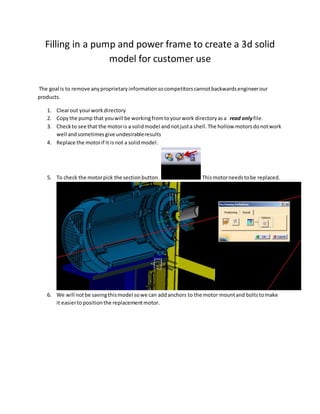
5. To check the motorpick the sectionbutton. Thismotorneedstobe replaced.
6. We will notbe savingthismodel sowe can addanchors to the motor mountand boltstomake
it easiertopositionthe replacementmotor.
2. 7. Anchorsadded.
8. Thisis a goodmotor to use.
9. Reconstrainthe replacementmotorusingthe anchoredcomponentsfromstep7.Update
model.
10. Erase the componentsthatare not necessaryforthe 3d model youare goingto create.(I.E.
shaftguard, sheavesetc.) Leave anything thatwill definethe limitsof the model oraddsto the
appearance.Fastenerstake upalot of memoryso the fewerthere are the better.
11. Openthe pumpin a newwindow.
12. Erase everythingthatdoesnotdefine the external dimensionsof the pump.Iusuallyleave the
mountinghardware thatmountsthe pumpto the powerframe.Here isa representationof
4. 13. Openthe casingproduct ina new window.Erase everythingbutthe casing.
14. Thisis still aproduct sowe will needtoopenthe casingina new window.
15. Expandthe tree and expandthe partbody.Start at the bottomof the tree andstart removing
bodies.Firstonthe listof destructionwill be the inserts.Theywere the lastthing addedandwill
5. be the firstthingwe remove.
16. Insertsremoved.
17. Scroll up the tree until the nextpartbodyfeature.Youcan usuallyignore the fillets.Tthese will
disapearaswe remove the differentpartbodies.Nextonthe hitlistare the bossholes and
adapterboss.Theycan both be removedatthe same time.
6. 18. Hide the visible sketch.
19. In thispumpthe nextthingsetfor removal will be the jackingscrew hole andthe flow
straightener.
7. Remembertoupdate the model aftereachdeletion.Checktomake sure the casingstill looks
like acasing.Hide the sketches.
20. Nextwe will attempttoremove thhesebodies.
9. 22. Nextitemtoremove.
23. You needtobe diligentincheckingthe appearance of the casingtomake sure it still looks
normal. Watch what happensif we erase the wrongbody.
10. We probablyshouldn’terase thatbody.Undothe deletionuntil the casinglooksnormal again.
You must be diligentincheckingthe casing forappearance aftereachdeletion.Undoanything
that detractsfrom the appearance.
14. We still needtofill inthisarea.Thiscan be a little trickyasthere are no2 pumpmodelsbuilt
and constrainedthe same way.Forthisparticularpumpwe can change a parameter.
15. Thisis the parameterwe needtochange.
The diameteriscalledoutasa radius in the parametersetting.
To matchthe diameteralreadypresent inthe pumpwe will use thisnumber.
17. Thisis the result.This producedanundesireable result.Undothe lastactionand lets
take a differentapproach.Itmakytake several undo’stogetback to the stable model.
26. The face (solidorange line) ispartof the intake shaft.Letsreopenthe sketchandsee if we can
modifythe sketchtofill inthe opening.
18. 27. We maybe able tofill thisinbychangingthe intake shaftagain.
19. 28. Openthe sketch for the intake shaft.Letsremove the 30.00 constraintanddrag the verticle lineto
be coincidentwiththe pinkface.
20. 29. Make the unconstrainedlinecoincidentwiththe face of the the visiblepinkbody.
23. 31. Thispocketis part of the backlinershaftbody. Openthe sketchandminuplate the lines toclose up
the hole. Remove anyunnecessarygeometry.
24. Here are the changesi made.I gotrid of the unnecessarygeometryandconstrainedthe lineto5mm
fromthe centerline. Thatwill leave aø10mm hole.Here isthe result.
30. 34. Openthe sketchfor groove 2. We will notdelete groove 3.
Lets simplifythe sketch.All of the groovesare notnecessaryforcustomeruse of thismodel.
We greatlysimplifiedthe geometryandremovedanyproprietaryinformationwhilemaintainingthe
overall appearance anddimensional propertiesof the model.Note thatthe Ø220mm diameteris
nowØ10mm.
38. 39. Expandthe tree and erase everythingbelow the lockwasher.Thisshouldbe whatyousee.
40. Openthe housingina new window.Erase everythingthatdoesn’taffectthe external appearance of
the housing.Thisiswhatyou shouldsee. Hide the svisible sketches.
45. Do a cross sectiontomake sure everythinginthe pumpandpowerframe hasbeen filledin.
46. This isnormal.The areas that lookhollow are where 2parts of the solidmodelsoccupythe same
space.It showsupas a void. Anotherof catiaslittle quirks.
48. Nowit istime to create the filesfor customeruse.We commonlyprovide .stpand.dwgfiles.The
customermayrequestotherfile types.Firstwe needtoturnthe separate modelsinto1 model.
49. The firststepis to combine all the separate modelsintoone model.Goto the tool tab
andselectgenerate “CATPartfromproduct”.
47. 50. Clickthe part numberat the top of the tree andit will fill inthe “New PartNumber”box inthe drop
downbox.
Make sure the “Merge all bodiesof eachpart in one body”is active.Thiswill create anew drawing
that lookslike this.
48. 51. Nextselectall of the partbodiesstartingat all the way to the bottomof
the list.It will looklikethis.
49. 52. Withall the parts selectedgotothe “Insert” tab andhit the “Boolean
Operations”buttonandselect“Assemble”.Then hitthe “OK”button.
50. This shouldbe the endresult.Justafew more stepsand we will be finishedwiththisconversion.
53. Create a newpart. Hit the tab and select“new”.A dropdownbow will appear.
54. Select“Part”and hitthe “OK” button.
55. Rename the defaultname tothe name of the pumpyouare creatingand hitthe “OK” button.
51. 56. This isthe new part drawingwe created.Rightclickthe
“PartBody”and hit“Define InWork Object”. Thiswill make
“PartBody”active.
52. 57. Hit the window taband selectthe previousdrawing.
58. Rightclickthe “PartBody”and select“copy”.
59. Go back to the part drawingwe createdonstep54.
60. Rightclickthe part numberatthe topof the tree and select“Paste Special”.
61.
Select“AsResult”andhitthe “OK” button.