Instructions | Primary Arms PLX8 Platinum 1-8x24 FFP
•
1 like•627 views

https://www.optics-trade.eu/en/primary-arms-platinum-series-1-8x24-ffp.html

Recommended
Recommended
More Related Content
More from Optics-Trade
More from Optics-Trade (20)
Recently uploaded
Recently uploaded (20)
Instructions | Primary Arms PLX8 Platinum 1-8x24 FFP
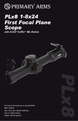
- 1. 1-8x24 First Focal Plane Scope with ACSS® GriffinTM MIL Reticle For Patent Information go to: goo.gl/2z62aS MPN: 610085 SKU: PA-PLX8-1-8X24F-GRIF-MIL UPC: 8 18500 01295 5 FINISH: MATTE BLACK ®
- 2. 2 TABLE OF CONTENTS Page 4 Achieving a Clear Reticle Picture READ THIS FIRST Page 4 Reticle Illumination Page 5 Establishing Zero Page 5 Resetting Controls Page 6 The Griffin MIL Reticle Page 9 Auto Ranging Page 11 Ranging With The MIL Grid Page 12 Specifications P L X 8 S E R I E S 3 P L X 8 S E R I E S INTRODUCING THE PLx8 1-8X24 FIRST FOCAL PLANE SCOPE The Primary Arms PLx8 1-8X24 First Focal Plane Scope is designed from the ground up with uncompromised craftsmanship and optical clarity in mind. Engineered and fully manufactured in Japan for durability and reliability, this scope is capable of handling heavy recoil and abuse. It is fast at 1X and extremely accurate at 8X, remaining true at all magnifications due to its first focal plane configuration. The ACSS (Advanced Combined Sighting System) is a giant leap forward in reticle design that utilizes bullet drop compensation correlated with range estimation, wind holds and moving target leads in one simple to use system. The ACSS Griffin MIL reticle increases first hit ratio and decreases time of engagement dramatically. It is a two part reticle, featuring bold horseshoe and chevron aiming cues for excellent speed at close range and a 0.5 MIL / MRAD holdover grid for accuracy at medium to long range.
- 3. P L X 8 S E R I E S 4 ACHIEVING A CLEAR RETICLE PICTURE Your PLx8 1-8x24 FFP scope comes with an adjustable Diopter Ring (D) that must be set to match your eye. Located at the rear of the eyepiece, it is marked simply [+ 0 -]. The diopter ring changes the focus of the reticle as you see it inside the scope. It does not change the focus of objects that you look at through the scope. Setting the diopter is a critical first step to successful precision shooting. You can set the diopter before you have even mounted the scope in its rings. 1. Turn the Power Ring (E) to the highest setting, 8x, and point the scope at a bright, featureless background such as blue sky or a blank white wall. 2. With your head in position behind the scope, look at the wall or sky instead. If you look through prescription glasses when shooting, wear them now too. After 5 or 6 seconds, close your eyes. 3. Now open your eye, glance through the scope and immediately see if the reticle is sharp or blurry. If you notice that the reticle seems blurry at first and then suddenly sharpens, your eyes have focused on the reticle itself instead of looking through the scope. You must adjust the diopter ring (D) and try again. 4. If the reticle was blurry, turn the diopter ring (D) and repeat the process again. The process will take multiple adjustments. Each time you repeat the process, ask yourself if the reticle was sharper or more blurry than before. The final adjustments may be very fine. If your eyes get watery or tired, walk away for a bit and come back to this later. 5. Once the reticle appears sharp as soon as you glance through the scope, the diopter is set for your eyes. Everyone’s eyes are slightly different, so the ideal adjustment changes from person to person. Many shooters will mark their correct diopter position with a little dab of paint or fingernail polish next to the 0 mark, in case the ring gets turned accidentally later on. Others will apply electrical tape around the diameter of the ring to hold it in place. This is a one-time adjustment. Reticle details may appear small when not looking at medium or long range targets, especially at low magnification. Shooting at those ranges is best done from a well-supported position using a bipod or sandbags. RETICLE ILLUMINATION The Reticle Illumination Knob (F) on the left side of the scope is marked with 11 numbers of increasing brightness. Between each number is an OFF setting. The lowest two settings, marked N1 and N2, are compatible with night vision devices and cannot be seen by the naked eye. Settings 1 through 9 follow and can be seen without night vision. The cap unscrews counter-clockwise, holding a CR2032 battery with the positive (+) side facing towards the cap. Reticle illumination at the lower settings is useful in low light situations like sunrise and sunset, or indoors. The highest two settings are “daylight bright” settings. Reticle “bleed out”, abnormalities and small imperfections may be visible when viewed indoors or in low light conditions at these two settings. This is a normal result of the reticle etching process. Abnormalities at these settings will not be visible when viewed in daylight conditions. Using these settings in low light situations will overpower your eye’s ability to see the target and make the reticle appear distorted. The right amount of illumination creates a clear contrast between the reticle and your intended target, without straining the eye. ESTABLISHING ZERO Using a bipod or sandbags, preferably on a bench or in the prone position, turn the Power Ring (E) to a high magnification to see your target as easily as possible. Dial in point of impact to coincide with the tip of the chevron. When the numbers on the adjustment knobs are adjacent to the scope body, the knobs are in the “locked” position and cannot be turned. Pull the knobs away from the scope body to unlock and adjust them. When sighting in your rifle, if your shots are hitting low, turn the Elevation Knob (C) counterclockwise to bring the point of impact up. If your shots are hitting to the left, turn the Windage Knob (B) counterclockwise to bring the point of impact right. Once you are finished sighting in, you can push the knobs back toward the scope body to lock them, preventing accidental rotation. RESETTING ZERO FOR WINDAGE AND ELEVATION You can reset your Windage (B) and Elevation (C) Knob positions to read “zero” after sighting in your rifle. Using a T30 Torx wrench, turn the locking screw in the knob cap counter clockwise and remove it. Carefully pull the outer knob straight away from the scope tube until it comes completely off. Line up the 0 mark with the center line underneath, and press the outer knob straight towards the scope tube to reinstall. Finger pressure is all that is needed. With the outer knob reinstalled, push down towards the scope tube to ensure the knob is locked and cannot rotate. Then carefully tighten the knob cap. Do not over torque the locking screw. P L X 8 S E R I E S 5
- 4. P L X 8 S E R I E S 6 P L X 8 S E R I E S 7 THE ACSS GRIFFIN MIL RETICLE The ACSS Griffin MIL reticle includes a center chevron aiming point, moving target lead dots, and a MIL / MRAD grid extending 15 MIL down and 6 MIL to each side of center. A thick CQB horseshoe surrounds the reticle to provide a bold point of aim that catches the eye instantly at low magnifications for quick reflexive shooting at close range. Ranging ladders are built into the left and right sides of the CQB horseshoe. CLOSE QUARTERS SHOOTING In close quarters, sight acquisition speed is paramount. For targets which might appear suddenly at close range, maximize field of view by selecting a low magnification. Many shooters can shoot quickly and comfortably at close range with both eyes open using 1x magnification. At low magnifications, the finer reticle features will become impossible to discern quickly, and the thick CQB horseshoe will appear as a small ring. At very close range, place the ring in the center of the target and fire immediately for extremely fast hits. Targets out to 100 yards can be engaged with impressive speed and surprising accuracy at 1x by centering the target inside the ring. With a bit of practice, this method of aiming becomes instinctive. Activating reticle illumination can help make the reticle faster to acquire at 1x magnification. If more precision is required and time allows, increase magnification and use the chevron tip as your point of aim. The chevron tip provides an infinitely small aiming point without obscuring the part of the target you want to hit, for a fast yet very precise sight picture. LEADING YOUR TARGET The “lead dots” on each side of the chevron are set for a target moving at a 90 degree angle to the shooter and travelling at 8.6 mph. Depending on the direction of the target’s movement, fire using the lead dots instead of the center chevron. If the target is moving left to right, use the left lead dot. If the target is moving right to left, use the right lead dot. The lead dots are best used from 100 to 300 yards and are highly effective on moving targets when using 5.56 NATO, 5.45x349, .308 Win, 6.5 Grendel, or other calibers with similar velocity. Due to the scope’s first focal plane configuration, the lead dots will function as intended at all magnifications, but they are easiest to use at higher magnifications. THE MIL GRID SYSTEM AND SHOOTING WITH HOLDOVERS Griffin MIL seamlessly incorporates the milliradian angular measurement system. The centerline “backbone” features wide hash marks at 1.0 MIL intervals and narrower hashmarks between them at 0.5 MIL intervals. To help with navigation, every 5.0 MIL the large hash marks are embellished with indicator bars on the ends, giving them a distinctive barbell shape. The full MIL Grid reaches 15 MIL down and 6 MIL left and right of center, with dots placed at 1.0 MIL intervals throughout. The PLx8 1-8x24 FFP Scope can be used as a traditional optic, where wind calls and range adjustments are “dialed in” using the adjustment knobs at 0.1 MIL per click, and the chevron tip always used as the point of aim. However, the Griffin MIL reticle offers a faster method, using the MIL grid as a precise holdover system to quickly adjust your point of aim without manually adjusting the scope at all. To shoot with high precision at medium range with any caliber, utilize a ballistic calculator program to calculate your bullet’s drop in milliradians as distance to target increases. Phone apps like Strelok Pro or Ballistic AE allow calculations to be run out in the field. The JBM GRIFFIN MIL OVERVIEW Auto Ranging Precision Zero +/- Moving Target Leads CQB Ranging Ladders MIL Grid LEADING YOUR TARGET Target moving left to right Target moving right to left Target moving right to left Target moving at 8.6 mph
- 5. 8 P L X 8 S E R I E S Trajectory calculator is free at http://www.jbmballistics.com/cgi-bin/jbmtraj-5.1.cgi. Shooters will often create a small chart of bullet drop values in MIL to reference, even attaching the chart to their rifle stock for easy reference. For example, a theoretical target is located at 500 yards distance. A ballistic calculator estimates that a 5.56 NATO bullet will drop approximately 3.0 MIL at 500 yards as it travels to the target. An ordinary scope would require counting 30 clicks of elevation to adjust the crosshair’s position physically. Using Griffin MIL, ignore the adjustment knobs and utilize the MIL Grid. Instead of aiming using the center chevron, count 3.0 MIL down to compensate for bullet drop and hold that point on the reticle over the target. That holdover point, 3.0 MIL down, becomes the new point of aim and the target can be hit without counting clicks at all. In this way the MIL Grid may be used like a bullet drop compensating reticle for any caliber. Ballistic calculator programs can also help calculate a custom “zero offset” that helps line up the bullet’s drop with the MIL hash marks at longer ranges. To illustrate, 5.56 NATO and 5.45x39 calibers zeroed at 100 yards can generally use the first four MIL marks to compensate for bullet drop all the way to 600 yards. For .308 Win, zero .5" high at 100 yards and for 6.5 Grendel, zero .75" high at 100 yards to achieve the same correlation with the MIL Grid. The MIL Grid dots located left and right of center can be used in conjunction with the ballistic calculator to compensate for wind. For a wind pushing left to right, shift aim using the marks to the right of center. For a wind pushing right to left, shift aim using the marks to the left of center. 9 P L X 8 S E R I E S HOW TO RANGE ESTIMATE USING GRIFFIN MIL Knowing the proper range to your target is crucial in order to use the right hold over on the reticle. Griffin MIL offers two methods of range estimation: horizontal and vertical auto-ranging, and MIL Grid ranging. Due to the first focal plane configuration of this scope, you can perform ranging at any magnification, but using high magnification usually gives the best results. Auto Ranging Horizontal auto ranging is correlated with the legs of the chevron and first three horizontal hash marks. Ranging is calibrated for center mass on targets 18" wide, and predators or small game with an approximately 18" measurement from shoulder to hip. From edge to edge, the chevron’s legs measure 300 yards distance. Horizontal auto ranging out to 600 yards is correlated with the BDC marks below. When using the MIL Grid to auto range while using 5.56 NATO, 5.45x39, .308 Win, or 6.5 Grendel, simply fit the target’s width inside the MIL mark that matches it, and fire (unless wind must be accounted for). With alternate calibers the method of ranging is still valid, but the bullet’s drop may not line up with the same MIL marks. THE RANGING LADDERS Located inside the horseshoe, ranging ladders are located to the left and right of center. Vertical ranging is calibrated for a 5'10" tall target. Looking through the scope at the target, line up the bottom of the target with the horizontal crosshair. The line that coincides with the top of the target indicates the distance to the target. For example, if the top of the target touches the line with a “4” next to it, the target is 400 yards distant. The ranging lines may be used as reference points to make more precise, yet quick ranging determinations. For example, a 5'10" target with its top midway between the “4” line and the “5” line will be approximately 450 yards away. HORIZONTAL AUTO RANGING 300 yards 400 500 600 EXAMPLE MIL HOLDOVER CORRELATION 5.56: Zero at 100 yards 5.45: Zero at 100 yards .308: Dial in .5” high at 100 yards 6.5 Grendel: Dial in at .75” high at 100 yards Common BZO or “Battle Zero” 100 yards 200 300 400 500 600
- 6. 10 P L X 8 S E R I E S Horizontal ranging is calibrated for an 18" wide target. Simply line up the target’s width with the appropriate line to determine range to target. For example, an 18" wide target that appears to be the same width as the ranging line with a “6” next to it will be 600 yards away. This method is useful when the target’s height is partially obscured, as with a target in tall grass. 11 P L X 8 S E R I E S HOW TO RANGE ESTIMATE USING THE MIL GRID Due to the first focal plane design of this scope, you can perform ranging at any magnification, but using high magnification usually gives the best results. To range estimate a target in yards using the milliradian system, take the following steps: 1. Know the target’s height or width in inches. For example, this target is 18" wide. 2. Multiply the 18" target size by the MIL conversion number 27.78. 18 x 27.78 = 500.04 Therefore an 18 inch wide target, converted, equals approximately 500. 3. With the target downrange, look through the scope at high magnification and measure the target using the 0.5 MIL hash marks. In this example, the target measures 1.25 MIL wide. 4. Take the converted 18" target number (500), and divide it by the 1.25 MIL measurement observed through the scope. 500 / 1.25 = 400 This target is 400 yards away. You can take any target’s known size in inches and multiply it by the conversion number 27.78. Observe the target’s measurement in MIL, and divide it by that measurement to determine range in yards. The general formula is: (Target size in inches) x (27.78) / Target measurement in MIL = Distance in yards GRIFFIN MIL RANGING LADDERS RANGING LADDER SECTION Auto range 18” 400 yards 500 yards 600 yards 700 yards 800 yards Auto range 5’10” 300 yards Range upwards from this point 400 yards 500 yards 600 yards 700 yards 800 yards 300 yards RANGING LADDER SECTION Auto range 18” 400 yards 500 yards 600 yards 700 yards 800 yards Auto range 5’10” 300 yards Range upwards from this point 400 yards 500 yards 600 yards 700 yards 800 yards 300 yards MIL RANGING 400 YARDS 18” wide
- 7. 12 P L X 8 S E R I E S 13 P L X 8 S E R I E S Magnification: 1-8X First focal plane Objective lens diameter: 24 mm Eye Relief: 3.9" – 4.0" Ocular lens diameter: 36 mm Exit Pupil: 11.7 mm - 3.0 mm Tube diameter: 34 mm Length (w/o lens covers): 10.5" A5056 aluminum, anodized matte black Weight (w/ battery, w/o lens covers): 26.9 oz. Field of View: 105.8 feet @ 100 yards at 1X 13.3 feet @ 100 yards at 8X Click Value: 0.1 MIL Total windage and elevation adjustment: 100 MOA / 29.01 MIL SPECIFICATIONS Red partial Illumination Night vision compatible Fast focus eyepiece Waterproof: Meets IP67 standard Fog resistant Fully multi-coated lenses Nitrogen purged High quality flip-up lens covers included Uses one CR2032 battery (included) Made in Japan Lifetime warranty (see website for details) FEATURES Specifications may vary and are subject to change without notice. LENS CARE Please do not use any organic solvent such as alcohol or acetone on your scope. First, blow dust or any foreign objects off of the lens. Then, use a soft cotton or microfiber lens cloth to clean any fingerprints or smears off the lens. Alternatively, you may use a piece of professional lens paper for further cleaning, if necessary. WARNING: Always ensure your firearm is unloaded (chamber empty and magazine removed) before installing optics or accessories. WARNING: Improper installation of firearm parts or accessories may result in death or serious personal injury. If you are not properly trained in the installation of these parts, have them installed by a gunsmith or armorer. REMEMBER: THE FOUR RULES OF FIREARMS SAFETY 1. Treat every firearm as if it were loaded 2. Never let your muzzle cover anything you are not willing to destroy 3. Keep your finger off the trigger until your sights are on target 4. Be sure of your target and what is behind it
- 8. 14 P L X 8 S E R I E S 15 P L X 8 S E R I E S NOTES NOTES
- 9. ® P L X 8 S E R I E S WARRANTY Your PLx8 Series scope is covered by the Primary Arms Lifetime Warranty. If a defect due to materials or workmanship, or even normal wear and tear, has caused your product to malfunction, Primary Arms will either repair or replace your product. You can find out more details at www.primaryarmsoptics.com. Email: info@primaryarmsoptics.com Phone: 713-344-9600 www.primaryarmsoptics.com