Cds Installation Guide | Leupold | Optics Trade
•
0 likes•1,258 views

https://www.optics-trade.eu/en/riflescopes/shopby/manufacturer-leupold.html

Recommended
Recommended
More Related Content
What's hot
What's hot (20)
Similar to Cds Installation Guide | Leupold | Optics Trade
Similar to Cds Installation Guide | Leupold | Optics Trade (20)
More from Optics-Trade
More from Optics-Trade (20)
Recently uploaded
Recently uploaded (20)
Cds Installation Guide | Leupold | Optics Trade
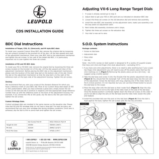
- 1. Installation of Target, CDS, ZL (ZeroLock), and M1 style BDC dials: To install your Leupold Custom Shop BDC dial, remove the original dial by loosening the set screw(s) located on the knurled rim of the dial. Lift the dial upward and clear of the adjustment mechanism. Place your new BDC dial on the adjustment mechanism and tighten the set screws. In the case of the target dial BDC, it is particularly important not to over tighten the three set screws. Installation of M2 and M3 BDC dials: To install your M2 or M3 BDC dial, remove the original dial by loosening the three set screws located on the knurled rim of the dial. Lift the dial upward and clear of the adjustment mechanism. Before placing the BDC dial on the adjustment mechanism, please note the location of the steel stop ball on the bottom side of the dial. Orient the dial on the adjustment mechanism so that the stop ball is to the right of the reference mark on the back side of the adjustment housing. Tighten the set screws. Zeroing: We recommend that you zero your scope at the shortest distance for which you have a reference mark on your BDC dial. Most of our Custom Shop dials begin at 100 or 200 yards/meters. After you have achieved a good zero, simply loosen the set screws on the dial and slip it positive or negative until the appropriate range reference number lines up with the reference mark on the back of the adjustment housing. For example, if you zeroed the rifle at 100 yards, slip the dial to the 100 yard mark and tighten the set screws. Custom Windage Dials: Custom windage dials are installed in the same manner as the elevation dial. Please note that M3 and M2 windage dials do not have a stop ball. For best accuracy, we recommend that you zero your windage dial during windless conditions. Once zero is achieved, slip the dial to the no wind mark and tighten the set screws. Set Screw Part # Allen Wrench Part # Target & CDS 33093 33094 (.050”) M1 Dial 42034 28952 (3/32”) M3 & M2 Dials 53992 37935 (1/16”) Adjusting VX-6 Long Range Target Dials 1. If scope is already zeroed go to step 3. 2. Adjust dials to get your 100 or 200 yard zero as indicated on elevation BDC dial. 3. Loosen the three set screws on the old elevation dial and remove dial assembly. 4. Install the new BDC dial assembly on the adjustment stem, make sure assembly is all the way down on adjustment stem. 5. Next rotate dial assembly clockwise until it stops. 6. Tighten the three set screws on the elevation dial. 7. Your dial is now set to zero. Package contents: • Screw on dial base • Adjustment dial • Stop collar • Hex key Note – the S.O.D. (screw on dial) system is designed to fit a variety of Leupold scopes that have coin-click and finger-click style adjustments – excluding VX-1’s. 1. If you have coin-click adjustments, there is no need to alter anything but if your scope has finger-click adjustments you will need to pop off the plastic piece that has the click markings on it. (Figure 1) Removing the plastic piece can be a bit tricky – we suggest using a bottle opener: 2. Take the dial base and screw it onto the threads that the plastic adjustment dial uses. (Figure 2) You should feel the rectangle “tail” of the dial base drop into the coin slot of the adjustment. Screw the dial base until snug, aligning one of the index marks to the 6 o’clock position. It’s not required, but you can use blue thread locker to secure the dial base to the scope. 3. Place the stop collar onto the dial base so that it seats flush. (Figure 3) Align the stop tab about 1/16th of an inch to the right of the index mark on the side of the dial base. Once the desired position is achieved, tighten down the three set screws on the collar. If you’re not able to align the zero on the dial base and the index mark, loosen the collar and readjust. 4. Install the provided dial over the post on the dial base. (Figure 4) Once the dial is flush against the base, tighten the set-screws with the hex key provided. BDC Dial Instructions S.O.D. System Instructions CDS INSTALLATION GUIDE Leupold & Stevens, Inc. | PO Box 688, Beaverton, OR 97075-0688 14400 NW Greenbrier Parkway, Beaverton, OR 97006-5790 USA Printed in the U.S.A. This publication may not be reprinted or otherwise reproduced without the expressed written consent of Leupold & Stevens, Inc. © 2017 Leupold & Stevens, Inc. All rights reserved. 1-800-LEUPOLD | 1-503-526-1400 | WWW.LEUPOLD.COM FIGURE 1 FIGURE 3 FIGURE 4 FIGURE 2
- 2. Installing the VX-6 CDS Dial and Zero Stop Assembly Included Items: • Custom CDS Dial with three .050” set screws • Zero Stop Ring • Pressure Sensitive Double Stick 3M Adhesive Ring • 5/64” Hex Wrench • .050” Hex Wrench CAUTION: Always verify and be certain that the firearm is unloaded and safe before undertaking any work upon it or the riflescope. It is recommended that you read these instructions completely and thoroughly prior to installing the CDS Dial and Zero Stop Assembly. Pay close attention to step 7, as the correct placement of the Zero Stop Ring is critical for the proper functioning of the CDS Dial Zero Stop. If you have questions prior to or during installation please contact the Leupold Custom Shop: CustomShop@leupold.com, 1-800-Leupold (538-7653) or (503) 526-1400. Installation: 1. Unscrew and remove the elevation adjustment dial cover. (The elevation adjustment dial is located on top of the scope with the windage adjustment dial at 90 degrees on the right side of the firearm.) (Figure 1) 2. Remove the plastic elevation adjustment dial by lifting straight up. Once the dial has been removed you will have a view of the adjustment gear ring and two 5/64” hex head screws. (Figure 2) 3. Using the supplied 5/64” hex wrench, remove both screws and lift off the adjustment gear ring. (Figure 3) 4. Using isopropyl alcohol with a soft clean cloth, thoroughly clean the flat surface around the raised shoulder of the adjuster assembly and the surfaces of the Zero Stop Ring. (Figure 4) Note: The Leupold Custom Dial System is designed to provide a hard stop that limits the Custom Ballistic Dial to one revolution, which prohibits over/under rotating the dial once it has been zeroed. If you DO NOT want the hard stop feature, allowing for multiple revolutions of the dial, proceed to step 9. 5. Peel the Pressure Sensitive Double Stick 3M Adhesive Ring from the large rectangular backing paper and install the ring (adhesive side up) to the zero stop ring as shown in figure 5. The adhesive ring must align around the diameter of the zero stop ring. Be sure to press down evenly around the entire adhesive ring. (Figure 5) 6. Gently peel the backing paper from the adhesive ring. 7. It is now time to install the Zero Stop Ring. The Zero Stop Ring is flat on one side and has a raised Dial Stop Tab on the other. It is extremely important that the Zero Stop Ring is installed in the correct position with the LEFT edge of the Dial Stop Tab aligned to the Zero Index Mark on the maintube. Carefully place the Zero Stop Ring (flat side with adhesive ring down) onto the raised shoulder of the adjuster assembly with the LEFT edge of the Dial Stop Tab aligned to the Zero Index Mark on the maintube. (Figure 6) 8. Press firmly and evenly around the entire Zero Stop Ring for 20-30 seconds to allow the pressure sensitive adhesive to activate. Note: Allow the adhesive to cure for 24 hours before using the CDS dial. 9. Place the Custom CDS dial on the elevation adjustment turret (loosen the three .050” hex head set screws if necessary). Align the starting zero number on the dial (usually “1” for a 100 yard/meter zero or “2” for a 200 yard/meter zero) with the Zero Index Mark on the maintube then tighten the three .050” hex head set screws. Caution: Do not over tighten! (Figure 7) Zeroing: We recommend that you zero your scope at the shortest distance for which you have a reference mark on your CDS dial. Most custom ballistic dials begin at 1 (100) or 2 (200) yards/meters. After you have achieved a good zero, simply loosen the set screws on the dial and slip (spin) it back until the appropriate range reference number lines up with the Zero Index Mark on the scope maintube. For example, if you zeroed the rifle at 100 yards/meters, slip the dial to the 100 yard/meter mark and tighten the set screws. If you have installed the Zero Stop Ring and run into the zero stop before achieving the amount of adjustment necessary to reach your desired point of impact, simply loosen the set screws and turn the dial away from the zero stop ½ to ¾ of a turn and retighten the set screws. Once sighted in reset the dial to zero as above. FIGURE 1 FIGURE 2 FIGURE 4 FIGURE 6 FIGURE 3 FIGURE 5 FIGURE 7