SAIL VERSUS HULL FORM PARAMETER CONFLICTS IN YACHT DESIGN
The Plastics Final Report
1. The Plastics
Epics 151-L
1500 Illinois St.
Golden, Colorado 80401
May 3, 2016
Dear Marine Debris Unlimited,
We are very thankful for your request for a proposal to collect and process plastic in the ocean. This is a
paramount problem that must be confronted immediately and urgently. As requested, we, The Plastics,
have come up with a method that will focus on the collecting aspect and will meet all of the
requirements that were instructed. We have developed a system that will collect ocean debris by using
arms to funnel it towards the middle of the boat where it is then caught by a conveyor belt and
transferred to a storage container. The contents following this letter will help you understand exactly
what our solution’s function and why it was selected. You will see the breakdown of cost, each
subsystem involved, and the effects it will have on the world. We composed several tests in order to
achieve a product that is both cost-effective and will outperform every idea. In conclusion, we hope you
make the correct decision in choosing the company that will make you the most money as well as
making the world’s oceans a cleaner place.
Sincerely,
The Plastics
Sam Slusser, Joseph Popp, Emily Greiman, Nassim Kabbara
The Plastics
Colorado School of Mines
3. 2
Table of Contents
Front Page
1 Executive Summary ………………………………………………………………………………………………………… 5
2 Introduction, Purpose and Sponsor Problem Statement …………………………………………………. 6
3 Team Problem Statement ……………………………………………………………………………………………….. 6
3.1 Stakeholders ………………………………………………………………………………………………….. 6
3.1.1 Specific Stakeholders
3.1.2 Bug Lists
3.2 End Users ……………………………………………………………………………………………………….. 7
3.3 Final Team Problem Statement ………………………………………………………………………. 7
4 Proposed Solutions Overview …………………………………………………………………………………………… 8
4.1 Solution Description ………………………………………………………………………………………… 8
4.2 Risk ………………………………………………………………………………………………………………….. 9
4.3 Benefits of Solution ……………………………………………………………………………………….. 10
5 Overview of Subsystems ………………………………………………………………………………………………….. 10
5.1 Catamaran Body …………………………………………………………………………………..………… 10
5.1.1 Subsystem Function
5.1.2 Fundamental Technology
5.1.3 Physical Properties
5.1.4 What it Looks Like
5.1.5 Interfaces
5.1.6 Proof the Subsystem Works and Test Results
5.1.7 Cost
5.1.8 Full Scale Production Considerations
5.2 Power ………………………………………………………………………………………………………….... 13
5.2.1 Issues to Consider
5.2.2 Calculations for Product
5.2.3 Testing
5.2.4 End Product and Prototype
5.3 Collection Arms …………………………………………………………………………………………….. 18
5.3.1 Function
5.3.2 Technology Involved
5.3.3 Physical properties
5.3.4 Subsystem Figure
5.3.5 Arm interface
5.3.6 Proof Subsystem Works
5.3.7 Final Production Considerations
5.4 Conveyor Belt ………………………………………………………………………………………………… 21
5.4.1 Conveyor Belt Interfaces
5.4.2 Subsystem Analysis
5.4.3 Future Improvements
5.5 Storage ………………………………………………………………………………………………………….. 23
4. 3
5.5.1 Storage Container
5.5.2 Removal Bin and Process
5.5.3 Actual Product Material and Dimensions
5.5.4 Testing
5.5.5 Locking
6 Assembly …………………………………………………………………………………………………………………………. 28
6.1 Interfaces ………………………………………………………………………………………………………. 28
6.2 Cost of Prototype …………………………………………………………………………………………… 29
7 Proposal for Plastic Processing ………………………………………………………………………………………… 30
8 Operations and Maintenance Summary ………………………………………………………………………….. 31
9 Concept Validation (Part One) ……………………………………………………………………….………………… 31
9.1 Testing ……………………………………………………………………………………………………………. 31
9.2 Proof of Functioning ………………………………………………………………………………………. 32
10 Concept Validation (Part Two) …………………………………………………………………………………………. 33
10.1 Impact of Testing ………………………………………………………………………………… 33
10.2 Total Cost Estimates ……………………………………………………………………………. 33
11 Conclusion ……………………………………………………………………………………………………………………….. 34
12 Bibliography …………………………………………………………………………………………………………………….. 35
13 Appendix …………………………………………………………………………………………………………………………. 37
5. 4
List of Figures and Tables
Figure 3.3: Shown are the two Great Pacific garbage patches, including a map of the currents that
construct them.
Figures 4.2.1 and 4.2.2: Construction of complete prototype on SolidWorks. Everything is scaled 1:12.
This is what our final works-like prototype should look like.
Figure 4.2.3: Side profile of entire prototype design.
Figure 5.1.3.1 and Figure 5.1.3.2: Catamaran hull All dimensions shown are in inches
Figure 5.1.4.1: Individual subsystem shown here
Figure 5.1.4.2: Mounts for Catamaran are shown
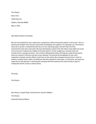
Figure 5.2.1: This a detailed diagram of how a photovoltaic solar cell works. In our case the load will be
our belt and propellers.
Figure 5.2.2: Map of solar radiation throughout the planet. Right around Hawaii is a good spot for solar
power.
Figure 5.2.3 Photograph of electric motor with battery pack and 3D printed attachment.
Figure 5.2.4: Back isometric view of solid works prototype.
Figure 5.3.3: A grey, foam pipe insulator is shown [5]
Figure 5.3.4: A visual representation of the flow of plastic towards the conveyor belt subsystem is shown
[8]
Figure 5.3.4.2: A visual representation of how the subsystem will float in the water and collect/funnel
debris as it moves. [9]
Figure 5.3.5.1 and 5.3.5.2: display visual representations of how the arms attach to the bow of the boat
and funnel trash towards the middle.
Figure 5.4: Shown is the CAD drawing of the conveyor belt
Figure 5.5.1: Back view of storage subsystem in SolidWorks.
Figure 5.5.1.2: The Ocean Vacuum. Developed by two surfers to clean up floating plastics around harbor
docks.
Figure 5.5.3: Zoomed in back isometric view of storage subsystem. This view does a good job showing
the interaction between the track and the wheels.
Figure 5.5.4: Storage subsystem prototype. Angle iron is placed inside the bin for later assembly.
Figure 5.5.5: Zoomed in image of wheel for sliding piece along
Figure 6.2: Cost estimate chart. From Table 6.2. Pie of Pie chart shows breakdown of materials and parts
list.
Figure 9.1.1: Shown is the finished prototype in action
Figure 10.2: Pie chart of the cost of the prototype. Broken down by each subsystem.
Table 5.1.7: Cost of Catamaran Prototype Hull
Table 5.2.1 Overview of Power Prototype Subsystem
Table 5.2.2 Overview of Power Actual Subsystem
Table 5.3.3 Overview of Collection Arm Dimensions and Price
Table 5.3.6 Overview of Collection Arm Prototype Subsystem
Table 5.5.5 Overview of Storage Prototype Subsystem
Table 5.5.5.2 Overview of Storage Actual Subsystem Estimated Costs and Dimentions
Table 6.2 Estimated Cost of Full Scale Design
Table 10.2 Total Cost of Prototype
6. 5
I. Executive Summary
“At least 267 different species are known to have suffered from entanglement or ingestion of marine
debris including seabirds, turtles, seals, sea lions, whales and fish. The scale of contamination of the
marine environment by plastic debris is vast. It is found floating in all the world’s oceans, everywhere
from polar regions to the equator” [1]. The Ocean is the single most polluted area on the Earth, and is
getting exponentially worse. After receiving the call for proposals from MDU, we developed a device
that will collect and store ocean debris.
Our product will be placed off the coast of Hawaii where it will collect and store floating surface plastic
and debris found in the Pacific Ocean. We chose this location because on March 11, 2011, a massive
earthquake struck a town called Tohoku, Japan, and the resulting tsunami flung 5 million tons of debris
into the Pacific Ocean [2]. In September of 2012, Japan Tsunami Marine Debris (JTMD) was discovered in
Hawaii, a majority of which lay along the shorelines and off the coast of the mainland [2]. Plastic litter in
the ocean is a major problem in today's society. Reports of this problem have been present since the
early 1970’s [3]. It is estimated that 4.8 to 12.7 million metric tons of plastic waste enters the world’s
oceans every year [3]. With every passing year, more plastic is being added to the ocean. This debris is
non-biodegradable and will remain in the ocean for at least another 1000 years [4]. At this rate, the
overflow of garbage will continue to grow and become more of a problem with every passing day. Our
task is to collect and process plastic from the ocean. Our group has chosen to prototype a model of our
collection system which is focused on collecting surface plastic from the ocean.
Through our research, we discovered two ideas that were very similar: The Ocean Cleanup and the
Ocean Cleanup Array. What these two ideas have in common is that they utilize a “V” formation because
it naturally directs plastic toward the vertex. At the vertex they each use a similar “conveyor belt-like”
process to collect floating plastic debris. Another thing these two have in common is that they are
extremely large and anchored, this means that the floating plastic must go directly into the “V”,
otherwise it will be missed. Since our design incorporates this “V” design we decided to improve upon it
by making our project mobile.
It can be placed near shores, or in the middle of the ocean, however it is designed to collect surface
debris, not deep-sea debris. The design consists of a catamaran-like hull with two arms extending out of
the front of the hull in a V-shape. This shape will funnel the plastic towards the center of our boat where
it will meet an inclined conveyor belt. This conveyor belt will pick up the trash, and move it up the belt
and towards the center of the boat where it will then fall into a removable containment system. This
unit, which is on a sliding rail system, can be removed from the rear of the boat when it is full and the
collected plastic can be deposited in a storage or recycling facility. The boat is powered by a motor and
is able to be directed in a specific path to maximize plastic collection.
Overall, the working prototype costs a total of $76.99. This includes the storage, power, catamaran,
conveyor belt, and the collection arms. The actual design will cost an estimated total of $108,928.29.
This includes all of the items listed above including labor and manufacturing.
7. 6
II. Introduction, Purpose and Sponsor Problem Statement
Currently the world’s oceans are a very messy place. Trash covers all of the Earth’s oceans and
unfortunately, this problem is not being handled urgently enough. Every day thousands of animals,
whether they be in the sky or the sea, are dying due to plastic or trash entanglement or ingestion [1].
Keeping this in mind, Marine Debris Unlimited is “seeking proposals for novel technological approaches
to collect and process plastic and shoreline debris.” The working prototype must not exceed $100 in
cost, but the final proposed solution has no cost limit. In addition, prototype testing must be safe to
animals and humans, and must not worsen the problem of plastic marine debris. As an assembled team,
our goal will be to give MDU an efficient, yet productive final design and start the push to tackle this
very concerning problem in our world’s oceans.
III. Team Problem Statement
3.1 Stakeholders
The first step in the design process is to gain an understanding of who is impacted by the problem and
why a solution is needed. The most important stakeholder is the marine life because they are most
effected. Innocent creatures are suffering due to humanity’s careless waste management. There is a
variety of ways that all sizes of marine life are harmed by the continuation of trash flow into the ocean.
Many species fall victim to entanglement caused by abandoned fishing nets, or swimming through
floating plastics. Another danger is the confusion between what is food and what is plastic; ingestion of
plastic causes malnutrition and may be poisonous to some creatures. This confusion does not only effect
marine life but also our friends in the sky. Figure 3.1 shows a picture of a deceased bird that has a
stomach full of plastic and trash. Lastly, if plastic stays in the water long enough, it will eventually break
down into micro-plastics and will be ingested much easier by organisms.
Furthermore, since these life forms are so heavily impacted, this effects many other forms of life and
economies. For example, the increase in oceanic debris results in a depletion of the fish population, this
depletion effects fisheries, thus driving up the price and effecting you at home. If the problem continues
to get worse, fisheries will be spending more time sifting through trash than actually catching fish. Many
coastal communities and humans are important stakeholders of this issue. Economies that rely on
tourism -- like Hawaii and the summer Olympics in Rio -- lose business due to trash washing up on the
shore.
3.1.1 Specific Stakeholders
The next step was not just recognizing the stakeholders, but also researching them further with
empathy exercises and research. The first stakeholder was sea turtles because they serve as a prime
representation of marine life. After conducting our exercise and experiencing the fragility of their lives,
the unfairness of the situation was clearly seen.
Next, we explored the human impact of oceanic debris. The second stakeholder researched was small
commercial fisheries. Due to the high amount of trash in the water, fisheries are unable to catch their
normal amount of fish. The ones they do catch may be poisoned or tainted because of ingested plastic.
We found that this drives up costs and may put many small scale fisheries out of business. As well as the
substantial depletion of fish, the additional time and energy spent avoiding trash significantly interacts
with daily, already difficult tasks.
8. 7
3.1.2 Bug Lists
To gain an even further understanding of the stakeholders, another empathy exercise called “bug lists”
were created both before and after our hands-on experiences. These lists are a great way to summarize
the circumstances that each stakeholder must cope with. Throughout the design process it was
important to refer back to these bug lists to ensure that implementing the Swimming V was solving each
of these issues. Not only was this a good checklist to make sure we were doing things right, they were a
reminder to why this is a problem we must be solve and who we are doing this for. It is our fault for
their problems, therefore it is our responsibility to solve them.
3.2 End Users
The Swimming V is currently designed for coastal regions and collecting surface plastics to a maximum
distance of 100 miles from the shore. This relatively short distance will allow the V to have a pre-
determined route, so that it will be full at the times it is closest to the shore. The V in coastal regions will
be manned so that it saves money on the initial costs if we were to have an automotive system. Due to
the short traveling distances, workers will also be willing to man the V instead of the deeper marine.
Finally, the end users will be coastal communities that would be willing to pay for the labor of manning
the V.
The V does have the capability to collect farther regions off shore, but that comes with a problem for
end users and would also require a manned version. An example of farther regions would be the Great
Pacific Garbage Patch. It will be very difficult finding someone willing to travel to the middle of the
ocean, stay there for long periods of time, and risk their lives just to collect trash. This is where the
Swimming V takes the next step. We are planning on developing an automotive system that does not
require the V to be manned. The self-propelling device will be able to be placed out in the water, have a
set programmed route, and would be solely reliant on its solar panels for fuel. This is a very difficult and
costly solution but would be extremely effective and energy efficient. It would require a primary ship to
take it to the garbage patch, but then could be turned on and left at sea to clean the ocean. If we can
program and control two rovers on Mars, we can program and control the Swimming V in the ocean.
The start-up costs on an automated system will be very high, but its benefits allow our device to be
placed in the most condensed area of oceanic debris. Therefore, we will be collecting more plastic in less
time, eventually producing a positive return once going through our processing procedure.
3.3 Final Team Problem Statement
We, The Plastics, compiled all the information we had on the issue at hand and generated a problem
statement that holds the intention of our design. Our problem statement is…
We are going to collect, sort, and process all surface plastic debris of the Coast of Hawaii.
A lot of factors when into this statement. From stakeholders to government policy, several different
constituents were kept in mind. The reason we decided to attack surface plastics was because it was the
most practical source of marine debris to reach. Plastics submerged in the ocean would call for more
expensive and laborious efforts. We discussed solutions involving submarines, but they do not reach the
9. 8
depths at which a majority of plastic is found. Therefore, to make the ocean cleanup easier and more
efficient, we decided on surface plastics as our target.
We then discussed the location of where we will launch our device. The final decision was off the coast
of Hawaii. As you can see from Figure 3.3, the ocean currents act as a conveyor belt for debris to be
swept into the two separate pacific garbage patches. From our research, we wanted to capitalize on
Hawaii because is it extremely close to the trash directing currents and is also United States soil. By
operating on U.S. territory, we can avoid any underlying oceanic agreements with other countries.
IV. Proposed Solutions Overview
4.1 Solution Description
Through our research, we discovered two ideas that were very similar: The Ocean Cleanup and the
Ocean Cleanup Array. What these two ideas have in common is that they utilize a V formation because it
naturally directs plastic toward the vertex. Then at the vertex they each use a similar ‘conveyor belt-like”
process to collect floating plastic debris. Another thing these two have in common is that they are
extremely large and anchored, this means that the floating plastics must go directly into the V,
otherwise it will be missed. Since our design incorporates this “V” design we decided to improve upon it
by making our project mobile.
Figure 3.3: Shown are the two Great
Pacific garbage patches, including a map
of the currents that construct them.
10. 9
It can be placed near shores, or in the middle of the ocean, however it is designed to collect surface
plastic, not deep-sea plastic. The design consists of a catamaran-like hull with two arms extending out of
the front of the hull in a V-shape. This shape will funnel the plastic towards the center of our “boat”
where it will meet an inclined conveyor belt. This conveyor belt will pick up the plastic, and move it up
the belt towards the center of the “boat” where it will fall into a removable containment system. This
unit which is on a sliding rail system, can be removed from the rear of the boat when it is full and the
collected plastic can be deposited in a storage or recycling facility. The “boat” is powered by a motor
and is able to be directed in a specific path to maximize plastic collection.
4.2 Risk
Despite best intentions, there is still a possibility that small fish can swim up to the boat and find itself
getting stuck on the conveyor belt. Such disturbances to the wildlife may happen and we cannot 100%
guarantee its ability not to intervene with marine life. The netting is low enough that marine life can
swim underneath and not get caught.
A very severe storm could cause possible fatal damage to the ship. It can normally stay afloat with ease,
but an intense natural catastrophe could cause the ship to tip over and the collected debris could spill
back into the ocean. At worse, the storm may separate the hulls and the ship would need significant
repair. A storm may also expose some of the electronic components of the ship. These parts will be
secured and water-proofed as much as possible, but there is still a risk that they may get wet and cause
the product to malfunction.
Although not a highly technical solution, this product will rely on functional electronic components. A
single point of failure with the power will cause all functionality of the ship to stop. If the motor were
also to fail out in the ocean, no trash would be able to be collected. Finally, if GPS on the boat were to
fail, the retrieval of the boat would be very difficult in the open ocean waters.
Figures 4.2.1 (left) and 4.2.2 (right): Construction of complete prototype
on SolidWorks. Everything is scaled 1:12. This is what our final works-like
prototype should look like.
Figure 4.2.3: Side profile of entire
prototype design.
11. 10
4.3 Benefits of Solution
The Swimming V can be placed near shores, or in the middle of the ocean. The ship can be used for
various scenarios. It was designed with making removing plastic simple and quick. For this reason, the
storage unit can easily be removed from the back. With a box like design these units can be easily
stacked and stored before they are sent to be processed. The ship proves to be highly buoyant and can
hold large amounts of plastic while remaining a float. It is easy to be driven and its versatility allows for a
large breath of application. From the open oceans to near coast of different parts of the world.
V. Subsystem Overview
The Swimming V project contains many components. As a team we were able to divide and categorize
the design into eight subsystems and then assign two per member. The subsystems that make up our
actual design are the catamaran body, its power sector, collection arms, conveyor belt, and the storage
unit. We wanted to focus on the Hawaii area because due to the ocean currents it is close to the most
condensed area of surface plastics, and it is American Soil. Our main objective is getting as much plastic
out of the water as possible, while keeping the cost at a minimum. If our process turns out to be far too
expensive, then we will have an even harder time finding people who will want to pay for it.
This report will discuss how we came to our ideas and why some were chosen over others. For the
power system, we will go over all the choices we considered and then give reasons why the final
solution was selected. We will also include what parts of the device that are powered by this system.
Finally, we will discuss the materials that are needed to make this subsystem, and what was
incorporated in our works-like prototype. And for the storage system, it will be structured very similar to
the power sector, first discussing all of our ideas and explaining how we came to our decision. Then,
discussing the sub-subsystems of the storage unit, including how we will remove the trash once it is in
the container. Finally, we will talk about the materials that go into creating this system. Both subsystems
are fairly complex so we will not be able to use all the desired materials for the works-like prototype due
to our budget. In the end, we know this idea will work and will save large amounts of aquatic lives. This
problem is one that needs to be solved and it is our responsibility to clean up after ourselves.
5.1 Catamaran Body
5.1.1 Subsystem function:
The subsystem that I was in charge of creating was the catamaran hull. The function of the catamaran
hull is to provide a buoyant platform for the rest of the subsystems to connect to. It is buoyant enough
to support the weight of the other subsystems, and is large enough for the other subsystems to attach
to it. Also, the hull must be hydrodynamic to minimize the effect of drag in the water
5.1.2 Fundamental Technology:
The hull was modeled after a catamaran because the hull couldn’t be one solid piece, because it
wouldn’t leave enough space for the other subsystems to fit it. Therefore, with the catamaran design
there is a “left” and a “right” hull, and there is empty space in the middle of the hull to allow for the
other subsystems to fit in. The catamaran hull utilizes a simple, yet hydrodynamic shape [5]. It utilizes
the principals of buoyancy and weight balance in order to support all of the other subsystems without
12. 11
sinking or tipping over [6]. The catamaran design is more efficient over normal hull shapes and can
provide a greater buoyancy using less hull material than normal hull shapes [7].
5.1.3 Physical Properties:
Originally the catamaran hull was going to be constructed out of fiberglass. However, after reconsidering
the versatility of fiberglass, a decision was made to construct the hull out of foam. Due to the fact that
the hull is made out of foam, it can be easily shaped and modified as changes need to be made. For
example, if the conveyor belt assembly cannot fit inside the “left” and “right” hull, the connecting rods
can be extended to increase the width of the catamaran. In addition, the connecting rods are made out
of
wooden dowel. The catamaran hull is fairly light and only weighs .3 pounds. However, it is able to
support 45 pounds. The dimensions of the catamaran hull are shown below [Fig 5.1.3.1, Fig 5.1.3.2].
Figure 5.1.3.1: (All dimensions shown are in inches)
Figure 5.1.3.2: (All dimensions shown are in inches)
5.1.4 What It Looks Like:
For the individual subsystem, the catamaran hull consisted
of the “left” and “right” hull attached together by two
wooden dowels. The “left” and “right” hulls were
constructed by cutting two 1.5”x5”x28” pieces of foam
using a hot knife, and then adhering them together using
3M 77 Multipurpose Adhesive. From there, a 20-degree
angle from front of the hull 4.5” was made. Lastly, two
Mounts
13. 12
mounting blocks 4”x5” were cut and adhered to the hull. The first block was adhered 3” from the
front end and the second block was adhered at the end of the hull. One hole was made in the center
of each of the mounting blocks 1/4” wide, 2” deep. Two wooden dowel rods were cut 22” in length
and then secured in the holes to connect the left and right hull. For the subsystem testing the
mounting blocks and wooden dowels had to be created to demonstrate if the catamaran hull
fulfilled its intended purpose [Figure 5.1.4.1]. However, for the actual prototype including all of the
subsystems attached together, the dowels and mounting blocks will be removed, and the left and
right hull will be directly connected to the conveyor belt using its mounts [Figure 5.1.4.2].
Figure 5.1.4.1: Individual subsystem shown here
Figure 5.1.4.2: The mounts are shown
5.1.5 Interfaces:
The catamaran hull is the support system for the rest of the other subsystems. It directly interfaces with
the arms, the conveyor belt, and the storage unit. The arms are secured to the front end of the left and
right hull using a gusset and adhesive. The conveyor belt is attached to the hull using block mounts and
adhesive. The storage unit is attached to the hull on an angle iron slider.
5.1.6 Proof the Subsystem Works and Test Results
The catamaran hull was tested in a pool 6 feet in diameter, and 1 foot in depth. It was concluded that
the catamaran hull has a weight bearing capacity of about 45 lbs. It is able to move through the water
holding this weight and it will sustain its balance [Table 5.1.6]. The catamaran hull must be tested with
all of the subsystems connected to it to make sure it functions properly. In addition, the catamaran hull
must be tested in an environment with wind and current to make sure it is able to travel the open sea
without tipping over. Based on existing catamaran designs, it should be able to maneuver through rough
seas with ease [7].
Table 5.1.6: Test Results
Trial 1 Trial 2 Trial 3 Trial 4
Weight
supported
20 lbs 30lbs 45lbs 55lbs
Moves
through water
with weight
Yes Yes Yes No
Does not tip
over with
weight
Yes Yes Yes No
14. 13
5.1.7 Cost:
The materials used for the catamaran hull were very inexpensive. The most expensive materials and
tools needed were provided by the workshop [Table 5.1.7.] If I were to have bought the 3M 77
Adhesive, it would have cost $16.99.
Table 5.1.7: Cost of Catamaran Prototype Hull
Materials Cost
Wooden Dowels $1.99
Foam Core $1.00
3M 77 Adhesive $0.00 (supplied by the workshop)
Heat knife $0.00 (supplied by the workshop)
Total Cost: $2.99
5.1.8 Full Scale Production Considerations:
The catamaran hull may have to be modified to include all the subsystems. If the subsystems are of
greater weight or size than anticipated, the hull will have to be fortified and the length and width will
have to increase. The hull can be fortified by wrapping it with waterproof tape which will increase its
rigidity and its strength. The hull is very easy to modify and will not require much labor. For the actual
prototype including all of the subsystems attached together, the dowels and mounting blocks will be
removed, and the left and right hull will be directly connected to the conveyor belt using its mounts.
5.2 Power Sector
To begin with the power system, we went through a lot of different ideas for sources of energy and how
we can incorporate that into electricity. Our final decision was to use solar radiation as the source of
energy. We will use photovoltaic solar cells to absorb the radiation and to power our device. This was
not a very easy decision to make, but we are sure it is the best option for our design. Other sources of
energy were considered when making this decision. We began with a simple gasoline combustion
engine, but knew that it might do more harm than good. The engine would require an extreme amount
of fuel to fulfill the V’s long journey. We will be producing harmful carbon dioxide emissions, pumping
them into the atmosphere. Also the process to refuel this engine would require either another ship to
constantly make extra trips, or have the device drive to shore. If the V drives to shore, then it is just
wasting energy. The next source we considered was because the device is in the ocean, we looked if
could to use hydropower. The only reliable source at this location in the ocean is using current energy.
Submerged turbines are able to turn the mechanical energy of the currents into electrical power. We
knew that it would be nearly impossible to use the currents as a source of energy for a moving device
out in the ocean. If the Swimming V was a stationary device, the current energy would be something to
look into. But, because our device needs to float and be mobile, it would not be a beneficial source. The
next source of energy we looked at was simply battery powered. However, we will need a lot of
batteries to supply the amount of energy that the device requires. The batteries will add weight and the
15. 14
buoyancy would have to be dramatically adjusted. Along with batteries, they will eventually become
dead and, with no recharging source, they will have to be replaced. This is similar to the issue we had
with gasoline but without the emission problem. Wind power is something to discuss but not to
consider. Although the wind is constant, the amount of energy created is far too small to be a large
enough source.
Furthermore, we decided on solar radiation to be our source of power. We can cover the entire top of
the device with photovoltaic solar cells. This would create enough energy and produce zero emissions. A
photovoltaic solar cell (PV cell) works by converting the energy of a photon (which is a particle of
sunlight) to electric energy. A PV Cell is set up in layers, from the top down we have an electrode, then a
nonreflecting shield, N-type silicon, P-type silicon, and then another electrode. The nonreflecting shield
is needed to absorb more photons which will increase the amount of electricity generated by the cell.
The other layers are explained by the chemistry of a what we call a PN junction. N-type and P-type are
“doped” compositions of silicon where the N-type has mobile electrons and the P-type has mobile
positive charged holes. A PN junction is where these two materials come into contact. Note that if you
apply a forward bias electric field to a PN junction then current is able to flow. However, in the case of a
PV cell, a photon delivers enough energy to excite the electrons up to the electrode, and the mobile
holes naturally fall down to the other electrode and a voltage is produced. This voltage can be hooked
up to a load and power whatever device. In our case the load is going to be the three electric motors
that will convert electrical energy into mechanical energy and power the Swimming V forward and
power the conveyor belt.
Now on to discuss what is being powered. We categorized the systems that need to be powered in two
sections, the conveyor belt and the propellers. We also have lights on top of the V to warn ships at night
to where the device is, but the reason why the lights are not considered is because they are on their
own individual system. Each LED light has a small solar cell that is wired to charge itself during the day
and then in the absence of sunlight, they turn on. So for the power subsystem the only things we need
to run is three electric motors. One motor runs the belt, and the other two power each propeller.
5.2.1 Issues to consider
There are a lot of questions regarding night and times where there isn’t a lot of sunlight. We have
considered a couple of ways to handle this problem. One being to simply turn the device off and let it sit
Figure 5.2.1: This a detailed diagram of how a photovoltaic solar
cell works. In our case the load will be our belt and propellers.
16. 15
and wait for when enough sunlight is available. This is not an awful option because although we want to
collect as much plastic as possible, we also know the window of opportunity to collect the plastic is a
pretty long time. We know that if the device misses a day due to a lack of sunlight it will probably make
up for it within a week. A big problem with plastic debris is that if it spends too much time in the water,
it will eventually break down into micro plastics. This is a major problem for the ecosystem because
micro plastics can be easily ingested. If the device spends too much time turned off, it is not being as
efficient as it could be. The next option we explored was placing a rechargeable battery system along
with the solar cells. Although this will add weight to the boat, it will be able to harvest excess energy and
at times when there isn’t enough sunlight, the V can switch over to the battery system. The third option
was to combine both ideas. Use a battery system to only power one section of the boat. The conveyor
belt requires less energy and the V formation will naturally direct the flow of trash into it. Therefore, we
can use a battery system to be charged during the days we have excess sunlight so that it can use that
stored energy at night to keep only the conveyor belt’s motor running and the collection and storage
process will continue. If tests show that we need more energy to be stored for the night, then we can
increase the surface area of the solar cells and more energy will be harvested.
The other problem, that was a big issue to overcome, was drag. With arms being so long and the
conveyor belt producing a force that countered the direction of our devices propellers, we needed a lot
of power to be generated by the solar cells. For our design, the arms of the V will be approximately 20
meters long and will have a stiff mesh drop about a half meter down to collect plastic. Note that the
Arm and collection process will be explained further by my partner Sam Slusser. But with that strength
comes drag, and we will be producing a lot of drag with stiff arms. Not only will drag be produced by the
arms but also by the drop down storage system that is placed beneath the device in the water. Also note
that all of this combined adds a lot of weight to device to be powered by solar cells. This issue can be
solved by physics and repulsion.
5.2.2 Calculations
This section discusses the amount of energy that will be needed for our actual and final project. Then
from that amount we can determine the area of solar panels that will require. Also to make these
calculations we are going to have to make a lot of estimates, and this is all scaled to the size of our
prototype, then we will scale it up to our actual design. The belt is 26 inches in total length and 12 inches
in width. It made one full rotation in 14.5 seconds. This totals to 1.793 in/sec which is equivalent to
0.04554 meters per second. But the repulsion due to the belt is pretty much negligible; the true
repulsion is due to the scoop that sticks out about 3 inches from the belt. If oriented in the perfect
position the scoop (mass when saturated is about 200 grams) will create a pulsing force of about 830
micro Newtons (this is calculated by the centripetal force create by the scoop traveling around the rod).
That force is so small for our prototype we don’t really have to consider it, but when we scale it to the
actual design then we will account for it.
The next repulsive force is created by the drag in the arms. The drag equation is represented as 𝐹𝐷 =
1
2
𝑝𝑢2
𝐶 𝐷 𝐴, where 𝑝 (1000 kg/m^3) is the mass density of the fluid, 𝑢 (2.24 m/s) is the flow velocity of
the object, 𝐶 𝐷 (0.60) is the drag coefficient (related to the objects geometry), and 𝐴 (0.2 m^2 from
SolidWork V arms) is the reference area. A lot of this depends on how fast we want our boat to travel. If
we want our boat to travel around 5 miles per hour or 2.24 meters per second. So the drag force is
about 281 Newtons, which is a lot of force. To overcome this force, the propellers will need to generate
about 630 N*m/s or 0.630 kiloWatts. From my research, silicon PV solar cells convert 22.1% of the suns
17. 16
energy in to electricity. And note that the Ocean’s surface at our location receives around 225 Watts per
square meter of solar radiation [Figure 5.2.2]. So to produce the 0.630 kiloWatts, and enough power for
the belt, we will need 12.7 square meters of photovoltaic solar cell arrays. Now this size is not realistic
but if we are able to slow down the velocity to just make the device travel forward it is very feasible to
power the Swimming V using only solar power. Even though that speed will be incredibly slow, we can
perform all of our intended functions. If we are able to reduce the velocity so that our actual large-scale
design could move forward and have enough power to store we can reach that level with 30 square
meters (323 square feet) of solar cell array, then the cost will be around $19,600 and will generate close
to 10 kilowatts of power. Yes, this is expensive but it will supply all the power that the Swimming V will
need for all its life, and the fuel cost is free with maintenance to refuel the whole thing.
And finally we need to implement a battery system to power the belt only during the night. These
batteries come in a variety of ways, but we will look at two options. The first being the Physio-Control
LIFEPACK, which only costs $210, but our system will probably require a lot of these batteries and they
are not very reliable. The next and most reliable option is the Tesla Solar Battery. A single battery is
designed to supply enough power from solar energy to recharge an electric car. Therefore, it is more
than enough storage for our conveyor belt. The only down side is that this technology is very expensive
($4,500). However, this is the technology that we are going to go with because it will require only one
and not have to worry about it not supplying enough power.
5.2.3 Testing
Like previously stated, incorporating actual silicon solar cells would be too expensive for our prototype,
so in reality, we are using a 7.4 V battery pack from a remote control plane. Even though the propellers
and motors for the boat are very important to our final design they will also not be in the prototype due
to costs and because the technology to electronically power a boat is already mature and implemented.
The only thing that I was looking for during this test was to make sure the two batteries supplied enough
power to spin the belt and sustain the load of all the plastic debris. Like we planned the conveyor belt
worked effectively and the battery pack was, although slow, strong enough to hold the added weight. In
conclusion the subsystem testing for this system was a success. Below is and image of what our battery
pack and electric motor look like.
Figure 5.2.2: Map of solar radiation throughout the planet. Right around
Hawaii is a good spot for solar power.
18. 17
However, to be safe my team agreed upon increasing the power of the entire system to handle more
plastic and a heavier conveyor belt. Since our subsystem testing was a success we wanted to keep the
same principles of how the motor attached to the conveyor belt. This excess weight will come from the
addition of more blades; the blades themselves will add weight, but also the addition of two sets The
result was for us to buy are new motor with more torque but with the same amount of revolutions per
minute. The motor along with its battery pack is below in Figure 5.2.3. A 3D printed mount was the last
addition so that the small rotating axel could be attached to the conveyor belt rods. After placing our
device in the water, this motor proved to be enough power and tested as a success.
5.2.4 End Product and Prototype
Due to the fact that we are on such a low budget for our actual works-like prototype, we will not be able
to put solar cells on the device itself. Therefore, we will use a simple battery pack to power our
prototype. From our subsystem testing we have discovered that two AA batteries supplied enough
power to run our conveyor belt. Now because we know that electric motors powering a boat is a
technology that is already mature and implemented, our prototype we will only need to power the
conveyor belt. Both components will be stored on top of the catamaran body.
Finally, this will be a conclusion of the actual subsystem with a detailed description of how it will look
and function. On the Swimming V we will use silicon photovoltaic solar cells to cover the top of the
catamaran body. These solar cells will be linked up to three separate electric motors via wires. There will
be an electric motor on each side of the catamaran body. They will use the electricity to spin stainless
steel rods that are connected to each stainless steel propeller: making the boat move forward. These
motors will be inside each side of the catamaran hull so that it does not interfere with the removable
storage system: which we will explain later in this report. The third motor will the spin a rod and supply
the power for the conveyor belt system that will be further explained by my partner Emily Greiman. This
subsystem is known to work due to the amount of research and already implemented technologies that
are out in the world today. The total cost of our prototype power system is only $10, but our actual
large scale power system should be around $20,000. This is the most expensive subsystem, but the
positive is that it is an initial cost and will be the only cost for the entire life of the device. If we were to
rely on regular gasoline it would be far less in cost but the amount of time that is wasted for refueling,
the long-term costs will eventually pass the solar technology.
Figure 5.2.3 Photograph of electric motor with
battery pack and 3D printed attachment.
19. 18
Table 5.2.1 (Overview of Power Prototype Subsystem)
Materials Costs Dimensions
Electric Motor $15 1 in dia (120 rev/min)
Battery Pack $5 RC Plane (7.42 V)
Table 5.2.2 (Overview of Power Actual Subsystem)
Materials Costs Dimensions
Solar Cell Array $14,700 22 square meters
Tesla Powerwall $4,500 1.118 cubed meters
Electric Motors $800 .12 cubed meters
5.3 Collection Arms
5.3.1 Function
The arms of this project are a major contributor to the project
because it’s the piece that collects and directs all of the plastic and
debris. This subsystem is also very crucial to our project because it is
the first step in the collection process. The function of this subsystem
is to collect plastic and debris that is on and just beneath the surface
of the water and then funnel it into the mouth of the boat and onto
the conveyor belt. The arms are angled in order to help funnel the
debris and reside at the bow of the boat.
Figure 5.2.4: Back isometric view of solid
works prototype.
20. 19
5.3.2 Technology Involved
Since this subsystem is pushed the only technology involved is
mechanical. It can withstand different elements of nature that could
potentially be encountered. Some examples of this have to do with
weather, such as waves, wind, hail, or large debris. In order to test these
environmental effects, objects were thrown at it, waves were created,
and large debris was placed in the water. When tested, the subsystem
held up well and had no structural changes at all. Drag was the main
problem that was encountered during these tests. When the system
was pushed faster than 3-5 miles per hour, there was a significant
increase in drag and began to bend the system backwards. When
moving slower than or equal to 3-5 miles per hour, there was no impact.
5.3.3 Physical Properties
There are two main parts that make up the arms, one is the drop down
collection system, the other is the floating surface collector. The drop
down collection system is comprised of a black aluminum mesh screen that is 3 feet long with holes
approximately a millimeter wide by a millimeter high. The floating surface collector consists of a black
foam pipe insulator, shown in Figure 5.3.3, that has a two-inch diameter. The hole in the middle, where
a normal plumbing water pipe would go, has a diameter of an inch and one-eighth. The weight of one
arm is 113.39 grams, the polyethylene pipe insulator weighing about 45 grams, and the aluminum mesh
screen weighing approximately 68 grams. Overall, one individual arm is 3 feet long and 6 ¼ inches tall. A
more organized description of all this data is shown in Table 5.3.3 below.
Table 5.3.3 Overview of Collection Arm Dimensions and Price
Material Price Density Function Secondary Function
Polyethylene
Pipe Insulator
$2.29 for a 6-
foot pipe
0.857-0.975
g/cm3
[6]
Collect surface
debris
Keep system afloat
Aluminum
Mesh Screen
$0.80 a foot
Total was $4.80
2.7 g/ cm3
[7] Collect debris 4 ¼
inches under
water
Provide weight to prevent
system from blowing away
5.3.4 Subsystem Figure
This feature, when attached to the final project, looks like a
“V” at the front of the boat. It is angled at 45 degrees from
the horizontal for steady flow of debris into the conveyer
belt section, while keeping it wide enough to pick up a
Figure 5.3.3: A grey, foam
pipe insulator is shown [5]
Figure 5.3.4: A visual representation
of the flow of plastic towards the
conveyor belt subsystem is shown [8]
1.5’
21. 20
large amount of debris. As it sits in the water, the top view will
look like in Figure 5.3.4 shown. From the front view, the aluminum
mesh screen would hang down from the polyethylene pipe
insulator, so it would look like what is shown in Figure 5.3.4.2. The
insulator’s intended purpose is to insulate water pipes in order to
keep heat inside and also to prevent cold water pipes from the
process of condensation. In order for the pipe to fit in the
insulator, there is a slit in the insulator as seen in Figure 5.3.3. For
our subsystem, we will be placing the aluminum mesh will fit
inside that slit. They are attached by a layer of adhesive that is
already placed in the polyethylene tubing. Currently this
subsystem is at a 1:12 ratio.
5.3.5 Arm Interface
My subsystem connects to the front of the actual boat. Using a wooden panel with screws, it will rest on
the inside of the boat walls for clear flow of debris, straight to the conveyor belt system. A visual for this
is shown in Figures 5.3.5.1 and 5.3.5.2. As it funnels trash and plastic towards the middle of the boat, the
conveyor belt, which is dipped into the water, will grab the
debris and continue to move it to the
storage container. As stated previously, the arms are at an angle of 45 degrees for maximum flow of
debris into the conveyor belt subsystem.
5.3.6 Proof Subsystem Works
To test our design and prove it worked, we placed it in a kiddie pool full of water that had a diameter of
6 feet and a depth of a foot. We placed 1500ml3
of plastic inside the pool and let our subsystems do
their jobs. The plastic that was put inside the pool varied from bottle caps to plastic strings to ping-pong
balls. Most of the plastic floated but some of it sank immediately. The arms were pushed through the
water using manpower to collect the plastic. The arms collected 100% of the floating debris that was
Figure 5.3.4.2: A visual representation of
how the subsystem will float in the water
and collect/funnel debris as it moves. [9]
4.25”
2”
Figure 5.3.5.1 (on the left) and 5.3.5.2 (on the right):
display visual representations of how the arms attach to
the bow of the boat and funnel trash towards the middle.
22. 21
either on or just below the surface, and 0% of plastic that was on the “ocean floor”. This is acceptable
because the purpose of this subsystem is to collect surface plastic, not the debris at the bottom of the
ocean. Some other results that were concluded from this test were that the system does indeed float,
worked extremely well, and was very affordable. In all, these arms costed a grand total of $7.62 after
Colorado tax (about 7.5%), and $7.09 without tax. However, even though it performed very well, there
were some problems that will need to be fixed. When the arms were pushed faster than 3-5 miles per
hour, there was a significant increase in the amount of drag acting on the aluminum sheet. It also
became fairly flimsy when the arm was pushed larger amounts of debris. The summary of this test
design was that an aluminum mesh sheet was fit into a slit in a polyethylene pipe insulator and then
placed into a kiddie pool filled with water in order to test how efficiently it would collect debris. A cost
table of all the materials used in this subsystem is shown below in Table 2.
Table 5.3.6 (Overview of Collection Arm Prototype Subsystem)
Material Cost Amount Total Cost of Material
Polyethylene Insulation $2.29 6’ $2.29
Aluminum Mesh Sheet $0.80/sq. ft. 6’ x 1’ $4.80
5.3.7 Final Production Considerations
After testing the subsystem there was a clear indication as to what parts of it needed to be enhanced.
One of these parts was the stability in the polyethylene pipe insulator. In the future this will need more
stability, and to do that, PVC pipe will be placed in the insulator. This will add stability and will help the
system float better as well. Another part to improve would be the attachment of the aluminum screen
to the insulator. Currently it’s only held together by a layer of adhesive on the insulator, but in the
future we will add zip ties going around the insulator and looping through the mesh screen. This will
hold the mesh tighter and reinforce the insulator. The material could eventually be changed from a
foam pipe insulator to a solid rubber cylinder at the same dimensions to scale. When attached to the
boat, the arms should be reinforced with steel brackets and then possibly even welded. The angle could
also be changed at this point to adapt to the situation or environment that it is placed in.
5.4 Conveyor Belt
The most efficient way to transfer the trash from the water to the storage component is a conveyor belt.
The Conveyor Equipment Manufacturers Association shows how much this technology is used and that
it is used in industries like manufacturing, mining, demolition, and recycling [3]. A lot of companies are
dedicated to producing modern conveyor belts showing that this technology is still highly in use.
The conveyor belt is modified to handle picking up floating plastics in the water. A simple motor turns
the belt by moving the top roller. The belt itself will be put into the water at an angle and will be secured
to the inside of the catamaran-like vessel. The track is made of a fabric mesh material with the idea that
the water will be able to drain from the plastic a bit before being placed in storage component. On the
track, cleats made of the same mesh material are reinforced with wire to form four blade like scoops.
Based off of previous designs of belts, it seemed that a belt with cleats was the best choice for the job.
RPI, a company that specializes in making belts, lists the benefits of a cross cleat belt saying that “it
increases loose material carrying capacity and prevents roll back” [2]. Seeing as the plastic being picked
up is loose material and the incline of the belt will cause plastic to roll back into the ocean, this design
choice was the best option.
23. 22
The conveyor belt measures to be 13 inches long and 12 inches wide. It would be placed at an angle of
22.6 degrees to ensure that the horizontal distance between the two rollers will equal 12 inches. The
roller on which the belt spins on is 13 inches long and has a diameter of 1 inch. The rod that secures the
roller has a diameter of ¾ of an inch. Each cleat is 12 inches in width and 4 inches in length.
Figure 5.4: Shown is the CAD drawing of the conveyor belt
This subsystem will be made by securing two rods with rollers and then attaching them onto the boat.
Small screws will be placed in the securing rod on both sides of where the rollers rest so the rollers stay
secured in one spot while still being able to move. They will be placed a foot apart and at an angle. The
belt will be placed onto the rollers and should be pulled tight by the rollers so traction helps the belt
move. If the proper tension of the belt is not applied, then the belt will slip. The motor will be placed at
the top and attached to the top roller. This is to assure minimum technical failures due to water as the
lower half shall rest in the water. The belt itself is made of the fabric ends being sewn together for a
continuous loop and virtual seamless transition. The cleats will also be sewed on to the belt. Wire will
hold the shape of the cleats and ensure that they have enough strength to pick up trash.
5.4.1 Conveyor Belt Interfaces
The plastic that is floating in the ocean is directed to the middle of the boat thanks to the arms and the
movement of the ship. From there it will be picked up by the conveyor belt. After traveling the length of
the track it will drop the trash off into the storage unit.
The rollers for the belt will be secured in the middle of the boat by rods. These rods ensure the stability
of the belt and act as the frame. They will be secured to the actual boat in between the two hulls of the
ship.
Since the trash will be floating in the water the belt will be slightly submerged at the bottom. The design
allows for this and accounts for loss of traction due to the water. Due to this interaction with water, the
material used for the belt and rollers are waterproof. The power source and the motor itself for the
conveyor must also be waterproof or there will be a critical failure in the product. Therefore, the motor
was placed at the top roller on top of the boat so that it may have minimal contact with water. Along
with the power source a switch will be placed at the top and made easily accessible to activate the
24. 23
product. The final design of the product will have a sealed power source and the motor will be more
water-proofed.
5.4.2 Subsystem Analysis
Four cleats were placed on the track. The motor was a 9-volt high torque DC motor. There were some
issues with traction when placed in the water, but the Velcro and rubber bands offered enough friction
to prove the concept. Overall, water did not seem to cause any failures with the test.
The test performed involved a small pool filled with water to a depth of about a foot. Ten pieces of
floating plastic was placed into the test bed and was allowed to float freely in the water. The boat was
placed in the water and turned on via switch. Once turned on it was monitored for 30 seconds. Once the
preliminary run was complete, for testing purposes plastic was pushed towards the belt. It collected 90%
of the trash. Small trash such as bottle caps or ping pong balls would get stuck in the cleats, but would
inevitably fall out.
Only one quantitative test was taken as it demonstrated that the belt idea would work and showed that
some improvements need to be made for the final product. Other qualitative tests were done in order
to show the conveyor belt could handle picking up trash that could fit in the cleats. A problem persisted
where the track would slip off the rollers which was remedied by adding a guard on one side of the
rollers. Overall, the test was a success as it properly demonstrated the design intent of the conveyor.
The belt worked while slightly submerged in water and was able to pick up floating plastic.
5.4.3 Future Improvements
A modification that has to be done is adding small little spikes to help catch the screen material and pull
it along. Currently, there is still not enough friction for the roller to grab onto the screen and pull it.
Although Velcro and rubber bands helped, to improve efficiency the small spikes should land right in the
little holes of the track material and help push it along. Without more traction the conveyor belt will be
useless.
5.5 Storage and Removal
Once we collect the trash by our V formation arms, and are able to get the plastic debris out of the
water via the conveyor belt, the next step is to be able to store what we collected, and then be able to
easily remove the debris from the Swimming V. This is my second subsystem, and it is called the Storage
and Removal subsystem. We considered a lot of things when discussing this subsystem, but the main
goal was to design a storage system that can will be able to hold about the size of a shipping crate full of
debris and also have an easy process to remove the plastic once it reaches that level.
5.5.1 Storage Container
25. 24
The end goal was to trap and store all of the debris that make it up the
conveyor belt. We had to consider a few things, the main being how
will we collect all of the debris off the conveyor belt and what is the
best shape for this system to have. Our original thinking was to do
something similar to the Ocean Vacuum technology, but instead of
having water be pulled through it we have a cylinder container with a
removable lining. But this would require a funnel system to accurately
transport the trash from the conveyor belt to the container, without
letting any trash fall out and back into the water. Furthermore, because
our conveyor belt is not extremely accurate with where it drops the
collected debris, we decided to change the container to a rectangular
pattern. That way if the edge of the container is the same width of the
conveyor belt, we do not need to incorporate a funnel system and the
trash can fall right into the unit.
After the shape was finalized, the next component was the size of the container. If we made our device
drive to the shoreline to drop off its collected plastics, it would be spending a lot of time traveling the
long distance and less time collecting more plastic. There is so much pollution in the water so we
decided that, although it may take more energy from a regular boat, we will have a second ship come by
when the device is closest to the shore and pick up the removable bin. This has a large impact on what
we want the size of the storage container to be. Therefore, we plan for the size of the container to be
equivalent to the size of a shipping crate. Now for our works-like prototype the conveyor belt is going to
be exactly one foot across in width, so the size or our container should be slightly over that mark. Also it
will need to be larger in length than width so that we can store more plastic as it comes in.
5.5.2 Removal Bin/Process
The next circumstance we faced when discussing the storage subsystem was that once we were able to
collect the plastic debris, we need to be able to remove it from our device in an easy and efficient
manner. Because the plastic comes into the container as individual pieces, the best way to take it out is
to line the inside of the container with an easy removable bin. To make it efficient we have to give the
bin docking areas that a crane can slide in and pick up the entire bin. Therefore, in our works-like
prototype we placed a second basket in our container to show that it is a different object and easy to
remove.
Figure 5.5.1.2: The Ocean
Vacuum. Developed by two
surfers to clean up floating
plastics around harbor docks.
Figure 5.5.1: Back view of storage subsystem
in SolidWorks.
26. 25
The problem we run into is that the actual bin is now placed under the conveyor belt. So there are two
possible ways we can get the plastic out if the container if it stays under the belt. One, we could open
the back of the container and allow the trash to just slide out. But because majority of the container is
under water, when the back opens, water will flow right in. This would add too much weight to the
Swimming V and not allow it to keep collecting the plastic debris. And the other possible method is to be
able to slide the belt out of the way and pull the trash out of the top of the container. This method
would not have a problem with water coming in and it would be easy for another ship to use a crane to
pick out the inner lining bin. But in order to move the conveyor belt we would have to use a lot of room
to also move the battery pack and the electric motor.
Then we discussed that the container with an inner lining bin does not have to always stay under the
conveyor belt. By using a drawer technique, we constructed a container that could move out of from
under the conveyor belt and be exposed so the crane could have easy access. This is the best solution
because we will be able to lock in the belt, battery pack, and motor. This has all the pros of the other
methods and limits all of their cons. But one problem for the actual ideal design is that the container
and bin have an open top. This means that if severe storms were in the area of our device, the container
might lose some plastic. The next step is to develop a solution to trap and hold the debris once they are
collected. With this we are still in our beginning stages of development, but the plan that we have
developed and sure will work is to have an automated system. Sensors within the container will sense
that when the level of collected debris reaches a certain height, the top will begin to close a “ceiling”
that stretches from the back to about the middle of the container. The reason why is will only stretch
that far is because there is still more plastic being collected, and since the conveyor belt only fills the bin
from the front this “ceiling” will not be in the way of the oncoming plastic. This will only happen when
the level of plastic in the container reach a height that is prone to getting out during large storms.
Figure 5.5.3: Zoomed in back
isometric view of storage subsystem.
This view does a good job showing
the interaction between the track
and the wheels.
27. 26
As you can see in the picture above, the storage system all begins with how it will
connect with the catamaran body. There are two tracks mounted on the inside
of each foam flotation; these tracks are made out of aluminum angle iron. The
actual design will use the same material because it is strong and extremely light
weight, however it will be longer and have more tracks to make sure the
container stays connected and suspended. Next, is the container and inner
lining bin. We made this out a plastic bin usually for bring things to college or
storing small things under a bed, and for the removable material we used a
smaller but perfect fitting white plastic utility basket. And the final section is
how we make the two components come together. The main piece of this
part is what we are using to allow the container to move along the track with
minimal friction. In the prototype this part is simply the roller wheel of a
screen door. This piece was too short to reach the track, and because it came with a screw, we attached
it to a piece of wood and then attached the wood to the container with a waterproof adhesive. The next
step is to add the on more slider pieces so that it will allow the unit to sustain more weight. Lastly, in the
odd case of the container breaking away from the body of the boat in some malfunction, the entire top
of the container will have a buoyant floating rim that if it were to capsize it would flip right side up, no
matter how much material is in it: a GPS would let us track it down can collect it for safe measure. The
final dimensions for the prototype is the width of the container plus both sliding pieces totals to 15 7/8
inches, the length 14 inches, and the track is 13 inches on both sides of the sliding pieces.
5.5.3 Actual Material and Dimensions
Now since our scale prototype is 1:12 we will have to use a lot of material for the final design. We also
want the final size of the removable bin to be the same size as a shipping crate. The materials we are
planning on using for the container is aluminum because it is very light and durable. And because the
volume must be 1,360 cubic feet (volume of a shipping crate) we will need about $2,808.99 of aluminum
material. This calculation is form the cost of aluminum being $0.69 per pound. We want the final
dimensions of the storage container to be 22’ by 40’. This will cover enough room to catch all the trash
off the belt and be small enough for an easy removal. The last material is the sliding wheel. This must be
extremely durable and tough material; therefore, we will make the sliding pieces out of stainless steel.
Figure 5.5.5: Zoomed
in image of wheel for
sliding piece along
angle iron.
Figure 5.5.4: Storage subsystem
prototype. Angle iron is placed
inside the bin for later assembly.
28. 27
5.5.4 Testing
The Storage Subsystem was problably the easiest to test. It consisted of two parts; test if the wheels
alone would be strong enough to suspend the entire bin, and if the bin was boyant enough so that if it
broke off the body it would not capsize, sink, nor lose all of the plastic. Because we were only testing the
subsystem, test one was simply holding the aluminum angle iron about 18 inches off the ground,
placinng them exactly 15 5/8 inches apart (the width of the container plus wheels), and then setting the
container on top of the flat surface. We knew that if the angle iron and wheels were able to handle the
force of gravity out of the water, then in the water it will be far easier. After testing neither the wheel,
attachment, track, nor wood support broke or bent and the test was successful. The second test was
placing the whole subystem in the water and seeing if it would be able to hold weight, be bouyant, and
slide under the conveyorbelt. This test consisted of simply dropping the container in the water and
adding weigt to it. However, this test was not all sucessful. Once placed in the water, the bin floated too
high above the surface and was not boyant at all. But by adding approximatedly 20 lbs in the container
the bin floated at the correct height. This means that our material is either not dense enough, or is too
light. Also, when it got to the right depth the boyancy was not good, meaning the weight had to be
distributed evenly and it was still tipping. This was a suprisingly easy fix. Because adding the weight was
getting the container to the right height we decided to just simply add 20 lbs to the system and made
sure it was in a fixed postion and evenly distributed. Now our boat was at a proper height to fit under
the conveyor belt and avoid the scoop. Next was to fix our bouyancy issue. Once the container could
reach the right height, we added insulating foam for copper piping around the edge of our container.
This foam is described as a toy water noodle with one side cut down the length of the cylindar, so it
could open to fit around a rounded surface, and lined with an adhesive. All we had to do was cut the
foam to equal the perimiter of the container (52 inches), add some of my waterproof adhesive for good
measure, then attach it to the rim of the container. When we put the storage subsytem back into the
water, the bouyancy was much better and the test was successful.
5.5.5 Locking
Now that we have proved that the track and wheels will work, the next step is to make the locking
system for when trash is being collected and then when it needs to be taken out. We be able to take the
container completely out without much of a problem. But we do not want this to unintentially happen
when we are in the middle of the ocean. Therefore, we have come up with the locking sub-subsytem.
This will be a drop down steel plate that securly drops from the catamaran hull, and creates a wall on
the track that will not allow the wheels to roll past. We will have some set limits, and the drop down
plates can easily be manually taken out and put back in. With is locking sub-subsystem, we can remove
the plastic when needed and securly lock it under the conveyor belt at different times.
Table 5.5.5 (Overview of Storage Prototype Subsystem)
Materials Costs Dimentions
Wood Slider $0.39 18”
Screen Roller $4.99 1” diameter
Utility Basket $3.79 11” x 13”
Aluminum Angle $4.29 16X48”
Storage Box $6.99 12” X 16.5”
Flotation Rim $8.00 48”
29. 28
Table 5.5.5.2 (Overview of Storage Actual Subsystem Estimated Costs and Dimentions)
Materials Costs Dimentions
Aluminum Container + Bin $0.60 per pound about
$2,808.99
300 cubic feet
Steel Slider Bars $100 1’
Aluminum Rack $100 13’
Flotation Rim $200 124’
VI. Assembly
Now that we have constructed all of our subsystems and made the proper changes to those that needed
improvements, the next step is assembling the entire device. This process called made tremendous use
of the saying, “Measure ten times and cut once.” Knowing that when we moved from the individual
subsystems to the assembly the components would not fit like perfect pieces of a puzzle. Also, not
everything was made to be adjusted, we had only a few things like the conveyor belt and the storage
container to be set dimensions and use them as a starting point. The body of the boat was the most
adjustable thing and by wrapping it all in duct tape we were able to add and subtract foam where it was
needed. After a few trial and error processes, the Swimming V finally began to take on its form. The
challenge was assembling our device with a foam body. This ruled out nails and other more structure
method of assembly. So for the prototype we turned to epoxy and duct tape, lots of duct tape.
6.1 Interfaces
The first step is to determine what the base or platform is to build upon. For this specific project it was
easy to determine what this base would be: The Catamaran Body. Because the distance across the
storage subsystem was 37 cm and could not be varied it was the first subsystem attached to the body.
The interface was between the aluminum angle iron and inner face of the body. The angle iron was an
easy attachment through metal epoxy and a little bit of duct tape on the end. The water level will be
right at the bottom of this angle iron that is why it was important to purchase water proof metal epoxy
for this assembly. Once the angle iron was the storage unit was to ballast the container to reach the
level of the angle iron. Then this interface is simple resting the sliding rollers on the track and the
storage unit can sit right under the conveyor belt and then easily slide out the back for the removal
process.
The next part to add on our assembly is the conveyor belt subsystem. Like discussed earlier, some
modifications had to be done to the conveyor belt rollers so that the interfaces could be more easily
connected. Before attaching this subsystem, it was essential that the distance at which the belt would
be completely stretched out was measured and marked on the boat. The reason being is that the tighter
the belt is the more traction (friction) will occur between the rollers and the belt and allow it to handle a
larger load. The interface between the body and the conveyor belt rods was to take a long strong brass
wire to be punctured into the foam body and bent so that it could slide into the top rod of the belt. So
on top the belt is attached to the body by a brass wire on one end but the other will be attached to the
motor which will be discussed later. The question here was how to attached a cylindrical PVC pipe to a
flat surface that will be under water. The first thing to be made was a metal clamp that look exactly like
the symbol Ω. This kept the rod from sliding forward or back when it was under water. To prevent the
bottom rod from sliding side to side, the entire clamp and PVC was wrapped entirely with duct tape.
30. 29
After the Conveyor Belt subsystem was assembled, the next objective was to make it move. The
prototype power subsystem was the next thing to add. Because the motor would be directly attached to
the top rod, the entire battery pack, the motor, and the switch will be mounted on the starboard sided
of the body. By placing a wooden stand under the motor, it was able to reach the perfect height of the
conveyor belt’s top rod. The motor was then attached to the rod by a 3D printed flat face and then hot
glued to the rod itself.
Finally, the last part to assemble was the V itself. This subsystem was the Collection Arms, and was the
easiest interface to assemble on our boat. In the theoretical design the interfaces were planned to be a
flat face on the end of the arm that would simply screw in to the sides of the catamaran body. But for
the prototype, wooden dowels were inserted in to the flotation components of the arms and then
screwed into an overhanging PVC pipe. That PVC pipe was then laid across the front of the catamaran
body and duct taped in place. This provides not only the attachment of the arms but stability to the
device overall. However, we found through testing that the pipe was a bit low, therefore our actual
design will go back to a flat face and screwed into the inside of the catamaran body.
6.2 Total Cost Estimates
Table 6.2 Estimated Cost of Full Scale Design
Actual Costs
Storage/Removal $3,208.99
Aluminum Container/Bin $2,808.99
Steel Slider Bars $100.00
Aluminum Rack $100.00
Flotation Rim $200.00
Power System $24,900.00
Solar Cell Array $19,600.00
Tesla Powerwall $4,500.00
Electric Motors $800.00
Collection Arms $3,687.30
Aluminum Tubing $1,778.40
Mesh Under hang (Steel) $1,908.90
Catamaran Body $20,000.00
Hull (Fiberglass) $20,000.00
Conveyor Belt $2,600.00
Mesh Belt and Blades $800.00
Steel Rods $1,200.00
Electric Motor $600.00
Propelling and Motion $6,912.00
31. 30
Honda Marine BFP 10 $6,812.00
Wiring connection $100.00
Labor $31,520.00
Manufacturing $21,000.00
Total Estimated Costs $113,828.29
According to Table 6.2 the Swimming V has an estimated total start-up cost of $113,828.29. These are
expensive costs but this is only a one-time initial payment. Because the Swimming V does not need any
refueling, the only future costs will be due to small maintenance checks and for the crew that is manning
the ship. Wages for these workers will be around $5,000 a month as they are at sea. The Swimming V
will consist of mostly Aluminum because it is a light metal and water resistant. That convers the
Collection Arms, Conveyor rods, and Storage container. The second most expensive section will be the
catamaran hull, this is due to the Swimming V’s size and weight requirements for strong buoyancy. But
lastly, the most expensive system will be the source of power. Solar panels are very expensive but in the
long run the Swimming V will save money because it has no need for refueling. Also with clean electricity
generation and zero emissions the V will avoid polluting the atmosphere while we try to clean the
ocean. And eventually with our processing system, that is a combination of reusing the plastic and
sending other collected trash to waste to energy generation, the Swimming V will have a positive return
on this investment and pay for itself.
VII. Proposal for Plastic Processing
Once the floating debris is retrieved, the next step in the project is to process the plastic. All collected
debris will be sorted based on whether it is plastic or miscellaneous debris such as seaweed or
driftwood. Once sorted out, the collected plastic will be placed into groups based on the type of plastic
Labor, $31,520.00
Manufacturing ,
$21,000.00
Power,
$24,900.00
Catamaran,
$20,000.00
Motion, $6,912.00
Collection Arms,
$3,687.30
Storage,
$3,208.99
Conveyor Belt,
$2,600.00
Materials and
Parts
54%
Figure 6.2: Cost estimate chart. From Table 6.2. Pie of Pie chart shows breakdown of
materials and parts list.
32. 31
it is made out of. With the plastic sorted it will then be sent to a plastic extruder that will re-process the
plastic and turn it into usable plastic. The technology exists as seen with the Plastic Bank's Recyclebot
[1]. The machine takes the sorted ocean plastic, shreds it, and then heats it up to the correct melting
point of the plastic. From there it will be extruded to usable printer plastic or to plastic beads that can
be reheated and molded into needed products.
VIII. Operation and Maintenance Summary
The Swimming V is very simple to operate and maintain. The Swimming V must be placed in a body of
water to operate. There are two versions of the Swimming V, the current version being a manned device
able to be driven along the coast. However, through further research and development, an unmanned
Swimming V will be produced to be able to tackle the Great Pacific Garbage Patch. This Swimming V will
be autonomous and be programmed to its specific function.
8.1 For the manned version:
To initiate the function of the conveyor belt, the switch must be turned on. Once the conveyor belt is
running, the engine can be started and the Swimming V can begin to travel a specific path towards
plastic. As the Swimming V moves towards plastic, the V-shape of the arms will funnel plastic towards
the center of the catamaran hull. As the plastic is concentrated, the conveyor belt will successively pick
up the plastic and transfer it to the storage unit. Once the storage unit is full of plastic, it can be
removed from the rear of the swimming V by use of the track and the plastic can be removed from the
unit. Once it is removed, the storage unit can simply be placed back onto the track and slid back into
place.
The swimming V must be checked every year for maintenance. It must be ensured that the Swimming V
is functioning properly. The weight distribution on the catamaran hull must be checked to ensure that it
is evenly balanced. In addition, the conveyor belt must be checked to make sure that the belt is rotating
properly, and that plastic is being picked up and deposited correctly.
IX. Concept Validation (Part One)
At the end of this section we will prove that our device has the capabilities to reach a goal of 90%
collection of surface plastics. Through numerous testing practices both on land, in the creek, and in a
still pool, the Swimming V eventually achieved our goal.
9.1 Testing
Once the V was assembled, the next objective was to hold our breath and put it back in the water. On
land the V seemed to be very heavy, but when placed in the water it’s buoyancy test was a success right
away. Next was to see if the collection arms worked if the boat was moving. This is when the creek came
into play. By facing the V upstream, we sent floating plastics down the water in a random array. This was
to simulate the V actually moving through the water and being propelled forward. All the plastics that
was in the range of the end of the V was directed to the vertex, which is where the conveyor belt is
located.
33. 32
Although the main test was to see if our conveyor belt was strong enough to handle the plastic load, not
allow the belt to slip, and dump the collected plastic into the storage unit underneath. We turned the
belt on in the creek and nearly busted our motor, because the current was far too powerful for the belt.
Therefore, the next place for testing would be a still pool. Without making any changes to the device we
placed it in the pool and turned the belt on. The blades began to spin around the rods but then once a
small load was put on, the motor actually stripped its connection to the rod and continued to spin but
not the belt.
Therefore, the last and final piece that was essential to our prototype was to construct an attachment
that went onto the motor and could be glued directly to the conveyor belt rod. The solution was to 3D
print a mound that could slide onto the motor and not stop nor slide off as a load was added onto the
belt. On April 20th
the Swimming V was placed back into the water and turned on. This time to simulate
the V being propelled forward we pushed the trash toward the belt because the arms already passed
their test. After adding the 3D printed mount the Swimming V could handle any size load of plastic that
we pushed up towards it. The blades did not allow any slippage of trash to come off the belt, and once
the plastic reached the top the belt dropped the plastic directly into the storage bin underneath. Once
all the plastic had a chance to be collected, the storage bin was rolled out the back and the inner lining
waste basket was removed, revealing that 82-90% of all surface plastic is collected and stored.
Figure 9.1.1: Shown is the finished prototype in action
9.2 Proof of Function
To prove that the basic concepts of the design would function, the four main subsystems were tested.
This included the conveyor belt, the catamaran hull, the storage unit, and the arms. The conveyor belt
was tested to make sure that the belt rotated properly, and that it was able to pick up and deposit
plastic correctly. The catamaran hull was tested to determine its buoyancy and if it was able to support
the weight of all the other subsystems. The storage unit was tested to conclude whether or not it was
able to slide in and out of the catamaran hull on its rail system. The arms were tested to make sure that
they properly funneled trash towards the center of the catamaran hull.
34. 33
X. Concept Validation (Part Two)
10.1 Impact of Implementation
Initial testing of the conveyor belt demonstrated that a high-torque motor was necessary to power the
device. The original, basic motor was not strong enough to power the conveyor belt when submerged in
water. Initial testing of the catamaran hull proved that the hull was buoyant enough the support the
weight of all the other subsystems. However, to improve durability and rigidity, the whole hull was
wrapped several times in water-resistant duct tape. Initial testing of the storage unit expressed that the
width of the spacing between the left and right sections of the hull needed to be slightly decreased in
order for the storage unit to fit more snugly. The initial testing of the arms proved that they were able to
funnel plastic without fail, however they had to be cut slightly because they were too large.
10.2 Cost of Prototype
Table 10.2 Total Cost of Prototype
Prototype Costs
Storage/Romoval $22.45
Wood Slider $0.39
Screen Roller $4.99
Utility Basket $3.79
Aluminum Angle Iron $4.29
Storage Box $6.99
Flotation Rim $2.00
Power Sector $20.98
Electric Motor $15.98
Battery Pack $5.00
Collection Arms $7.09
Polyethylene Insulation $2.29
Aluminum Mesh Sheet $4.80
Catamaran Body $9.49
Hull $5.00
Metal Epoxy $4.49
Conveyor Belt $14.58
Plastic Rods $2.39
Mesh Belt $1.20
Flower Wire $2.50
Velcro Roll $8.49
Total Cost of Prototype $76.99
35. 34
XI. Conclusion
In conclusion, our solution will pick up the most plastic for the least amount of money. After the initial
startup costs, The Swimming V will continue to make our team and investors’ money. Currently, our
solution is cheaper than the already existing projects by approximately 600,000 dollars [6]. The efforts
that are in use right now are The Ocean Array and Project Ocean Cleanup. Each of them are similar to
the way ours functions, as ours is a combination of the two. Our next step is to get the money in order
to start building our full scale design, and then place it off the coast of Hawaii. After that we will revise
and expand on some ideas that we notice or noticed while the project was in use. Our recommendation
is to place it off the coast of Hawaii and then to branch off of The Swimming V and make an unmanned
model for deeper into the ocean. Another recommendation our team has is to promote the widespread
use of advertisements asking people to stop littering and pay notice to what is happening to our oceans.
Storage, $22.45
Power, $20.98Catamaran, $9.49
Conveyor Belt,
$14.58
Collection Arms,
$9.49
Figure 10.2: Pie chart of the cost of the prototype. Broken down by each subsystem.
36. 35
XII. Bibliography
“Advantage of Catamarans” [Online] [Accessed 5 April 2016]
http://www.brighthubengineering.com/marine-history/83095-advantages-of-catamarans/
“Basics of Solar Energy,” Unversity of Oregon. [Online] Accessed 20 March 2016
“Buoyancy” [Online] [Accessed 5 April 2016]
“Chapter 5: The Ocean Heat Budget,” Texas A&M University. [Online] Accessed 25 March 2016.
"Marine Debris", Department of Land and Natural Resources, 2013. [Online]. [Accessed: 08- Apr-
2016]. Available: http://dlnr.hawaii.gov/marine-debris/
“Plastic Debris in the World’s Oceans,” 24 January 2007. Greenpeace. United Nations Environment
Programme (UNEP) [Online]. [Accessed 9 February 2016].
J. R. Jambeck, R. Geyer, C. Wilcox, T. R. Siegler, M. Perryman, A. Andrady, R. Narayan and K. L. Law,
"Plastic waste inputs from land into the ocean," Science, vol. 347, no. 6223, pp. 768-771, 2015.
S. Engler, "10 Ways to Reduce Plastic Pollution," 05 January 2016. [Online]. [Accessed 3 April 2016].
S. Tabatha, “How Does Hull Shape Affect the Speed of a Boat?” 26 June 2010. [Online] [Accessed 5 April
2016].
“The Drag Equation,” 05 May 2015. NASA. Glenn Research Center. [Online]. Accessed 03 April 2016.
http://hyperphysics.phy-astr.gsu.edu/hbase/pbuoy.html
http://oceanworld.tamu.edu/resources/ocng_textbook/chapter05/chapter05_06.htm
http://www.mademan.com/mm/how-does-hull-shape-affect-speed-boat.html
http://www.unep.org/regionalseas/marinelitter/publications/docs/plastic_ocean_report.pdf
http://zebu.uoregon.edu/disted/ph162/l4.html
https://www.grc.nasa.gov/www/k-12/airplane/drageq.html
37. 36
XIII. Appendix
Figure 3.1.1
Figure 5.3.4
XIV. Team Biographies
(Pictured Left to Right)
Nassim Kabbara – Freshman, Chemical Engineering Major, Master in Business Administration
Sam Slusser – Freshman, Mechanical Engineering Major, Master in Engineering Technology Management
Joseph Popp – Freshman, Mechanical Engineering Major and Energy Minor
Emily Greiman — Freshman, Computer Science Major and Music Technology Minor