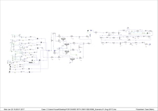
Flow Assurance Model of Gas Gathering Network with Seperation & Compression System
- 1. Wed Jan 25 19:09:01 2017 Case: C:UsersYousafDesktopFOR SHARE WITH OMV1062-6596_Scanario-01 (Aug-2017).hsc Flowsheet: Case (Main)
4-Gas
4-Water
op-100
Water
MIX-100
4-a
4-0
ADJ-1
A
14-Gas
14-Water
Water-2
op-101
14a
ADJ-1-2
A
MIX-101
14-0
Choke
(FV-1411)
4-1
Choke
(FV-11411)
14-1
E-1401
E-11401A/B
4-2
14-2
AH-100
H 4-5
5-Gas
5-Water
op-102
Water-3
5-0
MIX-102
5a
ADJ-1-3
A Choke
(FV-1511)
5-1
E-1501/02
5-2
15-Gas
15-Water
Water-4
op-103
15a
MIX-103
15-0
Choke
(FV-11511)
15-1
E-11501/02
15-2
AH-101
H
5-7
9-Water
9-Gas
Water-5
op-104
9a
MIX-104
9-0
ADJ-1-4
A
Choke
(FV-1911)
9-1
E-1901/02
9-2
8-Gas
Water-6
8-Water
op-105
8a
MIX-105
8-0
ADJ-1-5
A
Choke
(FV-1811)
8-1
E-1801/02
8-2
AH-102
H
9-7
MIX-106
20
2-Gas
2-Water
Water-7
op-106
2a
MIX-107
2-0
ADJ-1-6
A
Choke
(FV-1211)
2-1
E-1201
2-2
3-Gas
3-Water
Water-8
op-107
3a
MIX-108
3-0
ADJ-1-7
A
Choke
(FV-1311)
3-1
E-1301
11
10-Gas
10-Water
Water-9
op-108
10a
MIX-109
ADJ-1-8
A
10-0
Choke
(FV-11011)
10-1
E-11001/02
10-2
Compression-S-10
2
Sawan-11
Wellhead
T
11-0
Choke
(FV-11111)
11-1
E-11301/02
11-2
Sawan-13
Wellhead
T
13-0
Choke
(FV-11311)
13-1
E-11101/31101
13-2
AH-103
H
402-VIR
op-109
VS
Sawan-01
Wellhead
T
1-0.
Choke
(FV-1111)
13
E-1101/02
1-2
AH-104
H
Sawan-07
Wellhead
T
7-0
Choke
(FV-1711)
7-1
E-1701/02/03A-B
7-2
AH-105
H 7-4
1-4
MIX-110
M1-01
T2-Gas
T2-Produced
Water
P-8
M1-03
LP-Gas
LP-Produced
Water
P1
P4
T1-Produced
Water
Train-01/02
Manifold
Q-105
Manifold
to
Train-01
Slug
Catcher
P3
Manifold
to LP
Slug
Catcher
P6
Q-106
Q-107
Manifold
to
Train-02
Slug
Catcher
Q-108
T1-Compressor
Inlet Header
41
Q-109
LP to
Compressor
Inlet Header
36
Q-110
T2-To
Compressor
Inlet Header
31
Q-111
T2-Compressor
Inlet Headera
To
Header
33
Q-112
37 39
Q-113
To FEC
Compressors
Q-114
42
MIX-103-2
16
Sawan PW to
Hydro-cyclones
17
T2-Gas-2
T2-Produced
Water-2
P-8-2
Manifold
to Test
Separator
Q-108-2
Test To
Compressor
Inlet Header
31-2
Q-111-2
1
Test
Manifold
Q-105-2
24
SET-1
S
Test
Separator
(V-2004)
Sawan
PW
Volume
Tie-In-12
To
FEC
Inlet
Tie-In-11
Train-01
Slug
Catcher
V-2001
Flow
Spliter
LP Slug
Catcher
(V-5002)
Train-02
Slugacatcher
(V-3001)
E-5001A
18-2-2
V-5001A
25-2-2
TEE-104-2-2
96-2-2
97-2-2
LP-1-2-2
28-2-2
LP-2-2-2
29-2-2
P-LP1-2-2
P-LP2-2-2
MIX-106-2-2
30-2-2
BAL-2-2-2
B P-LP1+2-2-2
E-5002A
V-5001B
35-2-2
40-2-2
44-2-2
LP-3-2-2
45-2-2
P-LP3-2-2
E-5002B
46-2-2
E-5001B
49-2-2
E-5001D-2-2
53-2-2 V-5001D
54-2-2
HP (Exisitng
K-5001D)-2-2
55-2-2
56-2-2
P-HP-2-2
E-5002D-2-2
New
Piping
From(
Train-
A-B)
Q-100
PIPE-100
49-3
PIPE-101
50-3
PIPE-102
51-3
Q-101
Q-102
Q-103
PIPE-103
52-3
Q-104
48-3
PIPE-104
53
Q-115
PIPE-105
54
Q-116
PIPE-106
55
Q-117
PIPE-107
56
Q-118
PIPE-111
61
Q-122
PIPE-112
62
Q-123
63
PIPE-110-2
Q-121-2
PIPE-113
65
Q-124
PIPE-114
66
Q-125
67
PIPE-115
Q-126
PIPE-118
70
Q-129
PIPE-119
71
Q-130
22
HP
Discharge-2-2
FEC
IN+op-110
VS
ADJ-2
A
Model of Gas Gathering Network. (For FLOW
ASSURANCE)
To check the complete gas gathering network
behavior in future while flow rates of gas
become low & with increasing liquid flow rate.
and for prediction of pressure at down stream
of choke valves. which well will remain
adequate and which well will not flow in future
scenarios.
to predict the lower flow rates of wells for
which existing network will remain adequate
for specific pressure at FEC upstream
SEPERATION SYSTEM.
to check the adequacy of
liquid handling (Treatment
+Disposal of Produced
Water )system. how much
liquid will be . And
hydraulics of in plant
piping.
FEC FRONT END
COMPRESSION
SYSTEM.
To check the
compression train
behavior & in plant
Hydraulics, &
adequacy of AFCs.