2. current belief is that a large portion of the voltage hysteresis
originates from the asymmetric reaction pathways during
discharge and charge and consequently the existence of
different intermediate phases results in the large split in
electrochemical potential.14,19,20
According to the DFT-GGA
calculations and associated models, FeF3 is first lithiated to
Lix[Fe1−x
3+
Fex
2+
]F3 before full reduction of Fe to LiF/Fe during
discharge, and a series of Fe3+
-containing compounds
(Li3−3xFe3+
xF3) form sequentially during charge before
formation of a defect trirutile FeF3.14
However, the under-
standing of the reaction pathways is not fully justified by ex situ
solid nuclear magnetic resonance (NMR),15
pair distribution
function analysis (PDF),15
transmission electron microscopy
(TEM),13
in situ X-ray absorption spectroscopy (XAS),25
and in
situ X-ray spectroimaging experiments,26
all of which suggest
the existence of Fe2+
-containing intermediate phases during
and/or after charge. Additionally, different interpretations of
the intermediate phases that form during discharge exist
between the ex situ15
and in situ experimental works25
(e.g.,
trirutile Li0.5FeF3 vs rhombohedral Li0.92FeF3, respectively).
These discrepancies in reaction pathways have constrained the
understanding of voltage hysteresis and therefore need to be
reconciled through systematic and definitive studies into both
thermodynamic and kinetic aspects of the reaction mechanism.
Here we use in situ synchrotron XAS to track changes in Fe
oxidation states and local bonding structure during cycling of
three iron fluoride model samples, FeF2 nanowires (NWs),
FeF3 NWs, and FeF3 microwires (MWs). Combining results
from in situ TEM experiments and hybrid functional DFT
calculations (HSE06), we show that the reaction pathway is
symmetrical and as follows: rhombohedral FeF3 → trirutile
Li0.25FeF3 → trirutile Li0.5FeF3 ⇄ rutile FeF2 + LiF ⇄ Fe +
3LiF. However, reaction homogeneity (completeness and
spatial evolution of each electrochemical reaction) is strongly
influenced by reaction kinetics in these sequential multiple-step
reaction processes. Based on the new mechanistic under-
standing and results from galvanostatic intermittent titration
technique (GITT) experiments, we show that the large voltage
hysteresis of the FeF3 electrode is due to iR (ohmic) drop,
reaction overpotential, and difference in apparent potentials
which are a result of different spatial distributions of
electrochemically active phases. These results have general
implications for understanding voltage hysteresis in other
conversion electrode materials and provide the basis of new
strategies to minimize its adverse effect.
■ RESULTS
Iron Fluoride Model Samples. We prepared FeF3 NWs18
and MWs26
according to previous work and synthesized the
FeF2 NWs for the first time via thermal reduction of FeF3 NWs
using a small amount of glucose at 450 °C under flowing argon
(see Experimental Section for synthetic details; see morphology
in Figure S1a−c). The phase identities of these samples are
confirmed using powder X-ray diffraction (PXRD, Figure S1d).
Further TEM characterization reveals that all of these wire
samples are polycrystalline and made of attached particle
domains (Figure S2). We chose these materials as the model
samples because of their higher electrochemical activity at room
temperature compared with other iron fluoride samples.11,15,16
They can all reach near theoretical capacity at a moderate
current rate (Figure S3), which is critical for finishing the in situ
experiments in a reasonable amount of beam time and
collecting useful mechanistic information.
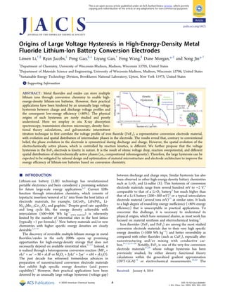
In Situ XAS on an FeF2 Electrode. We first studied the
reaction mechanism of an FeF2 electrode using in situ XAS as a
comparison to the FeF3 electrode, because Li-FeF2 is a simpler
conversion system (ideally only Fe2+
and Fe0
are involved) than
Li-FeF3 (Fe3+
, Fe2+
, and Fe0
are involved). Figure 1a shows the
electrochemical profile of a Li/FeF2 battery discharged at a
current of C/12 (1 C = 571 mA g−1
for FeF2) to ∼1.2 V. The
discharge cutoff voltage was chosen based on previous
literature15
and to ensure that the FeF2 electrode achieved
near theoretical capacity (2 Li per FeF2). During charge, the
battery was charged at a rate of C/6 to 4.2 V (the current was
doubled due to limited time). After the constant-current
charging step, a constant-voltage charging step was applied at
4.2 V until the current dropped to ∼C/50. Fe K-edge XAS
spectra were collected every 18 min during the electrochemical
Figure 1. In situ XAS results on an FeF2 electrode. (a) Voltage profile of an FeF2 NW electrode discharged at a current rate of 1/12 C (1 C = 571
mA g−1
for FeF2) and recharged at a current rate 1/6 C. (b) XANES and (c) EXAFS spectra taken at every 18 min during active discharge (+0.05 xLi
per spectrum) and charge (−0.10 xLi per spectrum), respectively. The black arrows indicate the isosbestic points shared by the XANES spectra.
Journal of the American Chemical Society Article
DOI: 10.1021/jacs.6b00061
J. Am. Chem. Soc. XXXX, XXX, XXX−XXX
B
3. cycling so that the change in average states of lithiation (xLi)
was +0.05 per spectrum during discharge and −0.1 per
spectrum during charge (see xLi for each spectrum in Table
S1). The change in Fe oxidation state and local bonding
structure was monitored, respectively, by X-ray absorption
near-edge structure (XANES, Figure 1b) and extended X-ray
absorption fine-structure spectroscopy (EXAFS, Figure 1c).
During discharge (xLi = 0 → 1.99 Li per FeF2, region I in
Figure 1), we observed that the absorption edge of the XANES
spectra gradually shifted toward lower energies, the white line
intensity concurrently decreased, and an isosbestic point is
shared by all the spectra (indicated by the arrow), indicating a
two-phase conversion reaction FeF2 + 2Li+
+ 2e−
→ Fe + 2LiF.
Accordingly, in the EXAFS patterns, the intensity of FeF2-
related peaks gradually decreases (marked with “−”) as the
intensity of Fe-related peaks increases (marked with “+”).
Standard EXAFS patterns of FeF2 and Fe are shown in Figure
S4 for comparison. It appears that FeF2 became lithium
saturated and started to decompose into LiF and Fe quickly, as
we observed the metallic Fe-related EXAFS peaks as soon as
the cell voltage hit the plateau at ∼1.75 V (<0.05 Li insertion).
This result is consistent with the calculations done by local
environment-dependent GGA+U (DFT-LD-GGA+U)29
but
different from those by DFT-GGA,14,17
which show that
lithiation of rutile FeF2 first produces a mixture of metallic Fe
and substoichiometric Li0.5FeF3 prior to producing LiF.14,17
Interestingly, we also observed progressive shifts in the
EXAFS peaks during discharge. For example, the Fe-related
peak shifted toward smaller R values as the discharge reaction
proceeded, decreasing from ∼2.3 Å (∼0 Li insertion) to ∼2.1 Å
Figure 2. In situ XAS and TEM on FeF3 NW electrodes. (a) Voltage profile of an FeF3 NW electrode discharged and recharged at a current rate of
1/10 C (1 C = 712 mAh g−1
). (b) XANES and (c) EXAFS spectra taken every 18 min during active discharge (+0.09 xLi per spectrum) and charge
(−0.09 xLi per spectrum). The black arrows indicate the isosbestic points. (d) Voltage profile of an FeF3 MW electrode discharged and recharged at a
current rate of 1/10 C, shown as a comparison to the NW electrode. (e) Phase evolution during the cycling of the FeF3 NW electrodes, which is
estimated by linear combinational fitting analysis of the XANES spectra. (f) High-angle annular dark-field, bright-field STEM images and schematic
illustration showing the microstructure of a bundle of fully lithiated FeF3 NWs, which is made of interconnected Fe domains surrounded by LiF. The
STEM images were recorded in the in situ TEM experiment.
Journal of the American Chemical Society Article
DOI: 10.1021/jacs.6b00061
J. Am. Chem. Soc. XXXX, XXX, XXX−XXX
C
4. (∼1.99 Li insertion). Further EXAFS fittings revealed that the
Fe−Fe bond length gradually decreases (Figure S5), which
indicates that the Fe nanoparticles formed initially have a larger
lattice constant than those formed later during discharge
(conversion), consistent with results from the previous in situ
TEM experiments on FeF2 nanoparticles.17
During charge (xLi = 1.99 → 0.02 Li per FeF2, region II in
Figure 1), the changes in both XANES spectra and EXAFS
patterns closely mirror what occurred during discharge,
indicating that Fe and LiF are gradually reconverted into a
rutile phase highly similar to FeF2 in the local structure. This
rutile phase most likely nucleates first at the interface between
the electrolyte and the active particles (now made of LiF/Fe
nanocomposites), where Li-ions are extracted and transferred
into the electrolyte most easily. When the cell was charged to
>∼3.3 V, some Fe was overcharged to +3 oxidation state, as
evidenced by the absorption edge of the XANES spectra
shifting toward higher energy and the Fe−F related peaks in the
EXAFS patterns shifting toward smaller R value than that of the
pristine Fe2+
F2 electrode. We also performed a linear
combination fitting analysis (LCA; see fitting examples in
Figure S6a and fitting parameters in Table S1) to estimate the
relative mole fraction of different Fe oxidations states (Figure
S7). The results reveal that the electrode was charged back to a
multiple phase mixture containing Fe, Fe2+
, and Fe3+
, not the
pure rutile FeF2 phase.
In Situ XAS and TEM on FeF3 Electrodes. Next, we
studied the reaction mechanism of an FeF3 NW electrode. An
Li/FeF3 battery was discharged at a current of C/10 (1 C = 712
mA g−1
) to 1.0 V and then charged at a rate of C/10 to 4.5 V,
after which a constant-voltage charging step was applied at 4.5
V until the current dropped to ∼C/50 (Figure 2a). Fe K-edge
XAS spectra were collected every 18 min during the
electrochemical cycling so that the change in average states of
lithiation (xLi) was about +0.09 per spectrum during discharge
and −0.09 per spectrum during charge (see xLi for each
spectrum in Table S2). The electrochemical profile (Figure 2a)
is divided into four different regions based on features observed
in the XANES spectra (Figure 2b) and EXAFS patterns (Figure
2c).
In discharge region I in Figure 2a−c (xLi = 0 → 0.78 Li per
FeF3), the Fe3+
in FeF3 is gradually reduced to Fe2+
with Li
uptake, as evidenced by the shift in absorption edge of the
XANES spectra. Meanwhile, the change in EXAFS peak
position and intensity indicates that the local structure deviates
from that of the original rhombohedral FeF3 and becomes
increasingly rutile-like, which resembles rutile FeF2 after 0.78 Li
insertion (Figure S8). We further carried out EXAFS fitting and
found out that the first set of data collected after discharge
region I (xLi = 0.79) could be best modeled using the scattering
paths generated from rutile FeF2 (see fitting results in Figure S9
and Table S2). For the FeF3 electrode at a state of lithiation of
xLi = 0.79, the coordination numbers are slightly smaller, while
coordination distances are slightly larger than those of rutile
FeF2 standard, indicative of a slightly defective rutile structure.
In another Li-FeF3 NW battery discharged at a slower rate of 1/
20 C, we observed two different isosbestic points in the XANES
spectra (Figure S10) in region I, which may be indicative of two
different trirutile LixFeF3 phases. No additional isosbestic
points were observed afterward. In the subsequent discharge
region II in Figure 2a−c (xLi = 0.78 → 2.82 Li per FeF3), in the
changes of the absorption edge, white line intensity, and
EXAFS peak position and intensity, we observed changes that
are highly similar to those which occurred during the discharge
of the FeF2 NW electrode (Figure 1, region I), indicating
reduction of a rutile Fe2+
-containing phase to metallic Fe. We
also studied the phase and microstructural evolution of the
FeF3 NW electrode by in situ TEM electron diffraction (ED)
and scanning transmission electron microscopy (STEM), which
show results consistent with the in situ XAS experiments. The
in situ ED patterns (Figure S11 and Movie S1) show that the
FeF3 NWs were first lithiated to form rutile FeF2 phase before
full reduction to metallic Fe. The in situ STEM (Movie S2)
shows that the lithiation reaction initiated from the surface and
propagated toward the core of each electrochemically active
domain. Notably, after being fully lithiated, the microstructure
of the FeF3 NW electrode is similar to that of the fully lithiated
FeF2 nanoparticles.16,17
Nanocomposites consisting of bicon-
tinuous LiF/Fe networks were formed (Figure 2f). The average
size of the Fe domains is 2−3 nm. As the starting point for the
charge process, this microstructure also provides the key to
understanding the phase evolution during delithiation. The
charge reaction (delithiation) most likely first initiates from the
surface of the active particles (now made of LiF/Fe
nanocomposites), where Li-ions are extracted and transferred
into the electrolyte most easily.
We performed LCA (see fitting examples in Figure S6b and
fitting parameters in Table S3) to estimate the relative mole
fraction of different Fe oxidation states (Figure 2e) during the
discharge (and charge) of the FeF3 electrode. We found that a
noticeable amount of Fe (>5%) already existed at xLi = 0.61 and
Fe3+
, Fe2+
, and Fe coexisted in the electrode between xLi = 0.61
and 2.15 (<5% Fe3+
, Figure 2e, Table S3). This result indicates
that the reduction of Fe2+
to Fe had already started on the
outside (Fe2+
-containing region) surface before the first
reduction (Fe3+
to Fe2+
) fully finished in the whole electro-
chemically active particle. An interesting question is what Li
composition in the Li-FeF3 system is necessary for metallic Fe
to begin forming, since different values xLi = 0.75, 0.92, or 1.0
were previously reported in FeF3/carbon nanocomposite
samples.14,15,25
In order to understand this issue, we studied
the reaction mechanism of FeF3 MWs for comparison (Figure
S12), which consist of larger particle domains than the NWs
(Figure S2). The FeF3 MW/Li cell was cycled at the same rate
as the FeF3 NW/Li cell, but its voltage profile (Figure 2d)
shows different features. The first sloping plateau at higher
voltages (region I) is much shorter, but the second flat plateau
(region II) is much longer than those of the FeF3 NW/Li cell.
Accordingly, the XANES spectra and EXAFS patterns of the
FeF3 MW electrode (Figure S12a−c) are also different from
those of the NW electrode (Figure 2a−c). LCA fittings
performed on the XANES spectra (fitting examples in Figure
S6c and fitting parameters in Table S4) reveal that a noticeable
amount of metallic Fe started to exist at xLi = 0.31 (>5% mole
fraction) and Fe3+
, Fe2+
, and Fe coexisted in the electrode until
xLi = 2.41 (Fe3+
< 5%, Figure S13 and Table S4). We also note
that the energy density of the Li-FeF3 MW battery is lower than
the Li-FeF3 NW battery due to the loss of the high-voltage
plateau.
The comparison between the reaction behavior of FeF3 NWs
and MWs reveals how reaction homogeneity and voltage
profiles (energy density) are affected by the size of the active
domains, which correlates with the reaction kinetics. As shown
by the in situ STEM experiment (Movie S2), the lithiation
reaction of FeF3 proceeds from the surface to the core of each
electrochemically active domain. In FeF3 MWs that consist of
Journal of the American Chemical Society Article
DOI: 10.1021/jacs.6b00061
J. Am. Chem. Soc. XXXX, XXX, XXX−XXX
D
5. larger active domains (and thus smaller surface area) than the
NWs, the applied current (1/10 C) is more likely to exceed
what the reaction kinetics (Li+
and/or electron transport) can
keep up with. Therefore, the Fe2+
-containing rutile phase
produced in the initial reduction (lithiation) on the outside is
further lithiated to produce LiF and Fe early at xLi = 0.31 before
the interior FeF3 domains can begin to react (see schematic
illustration in Figure S14). The occurrence of the reduction of
Fe2+
to Fe dictates the voltage profile despite the presence of
unreacted FeF3 at the interior so that the second flat plateau
becomes much longer (Figure 2d). By contrast, in the NWs,
faster reaction kinetics (shorter distance for Li+
and/or electron
transport) allow the first reduction step (Fe3+
→ Fe2+
) to
further complete before Fe formation (at xLi = 0.61).
Furthermore, in the FeF3/carbon nanocomposite samples
reported previously,14,15,25
even smaller particle size, better
electrical contact afforded by the carbon matrix, and small
current densities likely facilitate the first reduction to complete
even more, which explains the initial formation of Fe
approaching xLi at 1.0. Now we can see that xLi is better
considered a measure of the state of lithiation averaged within
the entire electrode, and it does not necessarily reflect the
stoichiometric information on the LixFeF3 phase that readily
extrudes Fe upon further lithiation, especially in the kinetically
limited situations (such as the MWs). It is possible that in all
cases Fe starts to form at y = 1, but the existence of unreacted
FeF3 phase at the core of the active particles leads to xLi < 1.
These results illustrate the critical role of reaction kinetics and
inhomogeneity in governing the conversion processes and
voltage curves for the FeF3 conversion electrode and have
implications for other electrode materials operating through
sequential multiple-step processes.
Additionally, we compared the electrochemical capacity with
the capacity estimated from the LCA fittings for the FeF2 and
FeF3 NW electrode and found reasonable matches (Figure
S15). These results suggest that electrolyte decomposition (or
any other nonmetal-center side reactions) does not contribute
significantly to the observed discharge capacity in the iron
fluoride conversion electrodes studied in this work (when low
cutoff voltage ≥1 V is used). This reaction behavior is different
from metal oxide conversion electrodes that are discharged to
lower voltages (<1 V),28,30−33
in which additional capacity was
often observed.
During charge of the FeF3 NW electrode (region III of
Figure 2a−c, xLi = 2.82 → 1.03 Li per FeF3), the changes in
XANES spectra and EXAFS patterns not only mirror what
occurred in discharge (region II of Figure 2a−c) but also were
highly similar to those observed during the charge of the FeF2
electrode (region II of Figure 1). EXAFS fitting was also
performed, and the data could be best modeled using scattering
paths generated from rutile FeF2 and Fe (Figure S16). These
results provide clear evidence that a rutile-FeF2-like phase is
formed during charge of the FeF3 electrode. These findings are
actually consistent with previous results from ex situ NMR and
PDF experiments15
but in disagreement with the DFT-GGA-
based reaction mechanism,14,17
which suggested formation of
Fe3+
-containing intermediate phases rather than the FeF2
intermediate during charge. In fact, we only observed oxidation
of Fe2+
into Fe3+
when the cell voltage exceeded ∼3.3 V in
charge region IV (Figure 2a−c, xLi = 1.03 → 0.53 Li per FeF3),
as evidenced by the absorption edge further shifting toward
higher energies. Further, the local structure at the final state
(0.53 Li per FeF3) still resembles rutile FeF2. According to
EXAFS patterns, the Fe-F peak position is slightly smaller than
that in rutile FeF2 but larger than that in rhombohedral FeF3
(Figure 2c) in R value. Therefore, we suggest that some trirutile
Li0.5FeF3 may exist at the end of the charge process.
DFT Calculations and Reaction Pathway of FeF3
Electrodes. To corroborate the experimental findings, we
performed a detailed multicomponent phase analysis using
DFT calculations of materials in the Li-Fe-F ternary system.
The DFT calculations were performed using GGA, GGA+U,
and hybrid HSE functionals,34
which have been shown to more
accurately reproduce experimental formation energies and Li
insertion voltages for transition-metal-containing compounds
than GGA.35,36
The Li-Fe-F phase diagrams calculated using
GGA and GGA+U are shown in Figures S17 and S18,
respectively. The results are consistent with those previously
reported (GGA,14,17
GGA+U29
). The HSE phase diagram
shown in Figure 3a is very similar to the GGA+U diagram
(Figure S18), with the exception that Li0.25FeF3 is not stable
from GGA+U. As HSE is a somewhat more general method
than GGA+U (due to GGA+U generally requiring a fitted U for
every transition metal), we chose to include and discuss our
HSE results in the main text and provide our GGA+U (and
GGA) results in the Supporting Information section for
comparative purposes. In all the phase diagrams presented in
this work (Figures 3a, S17, and S18), the red dots represent
stable phases, the black dots represent materials that were
predicted to be unstable, and the purple dots are important
composition points where no lithiated FeF2 or FeF3 materials
were calculated due to an insufficient number of interstitial sites
for Li insertion.
When examining the stable FeF2 lithiation path (green
dotted line in Figure 3a), FeF2 immediately begins to dissociate
upon lithiation to precipitate metallic Fe and LiF. This three-
phase region persists over the entire lithiation path until xLi = 2,
at which point the reduction from Fe2+
to metallic Fe is
complete and produces a two-phase mixture of metallic Fe and
LiF. This lithiation path is consistent with the in situ XAS
results on the FeF2 electrode (Figure 1, region I) and the
previous DFT-LD-GGA+U calculations,29
but clearly different
than the one predicted by DFT-GGA calculations.14,17
In
delithiation of the Fe/LiF (1:2 in mole ratio), FeF2 should be
formed as the stable phase, but Li0.5FeF3 may also be produced
from FeF2 if there is excess LiF, which is likely the case at the
surface of the active particles and indeed observed by the in situ
XAS experiment (Figure 1, region II).
The stable lithiation path for FeF3 (red dotted line in Figure
3a) shows direct Li intercalation when x ≤ 0.5. Upon lithiation
to xLi = 0.25 (Li0.25FeF3), the pristine rhombohedral FeF3 phase
is no longer stable, and a phase change to the defected trirutile
structure occurs. This defected trirutile phase is stable up to xLi
= 0.5 (Li0.5FeF3), after which dissociation to FeF2 and LiF
occurs because no more interstitial sites for lithium insertion
are available. When xLi = 1, all Fe3+
has been reduced to Fe2+
,
and the system is a two-phase mixture of FeF2 and LiF. Further
lithiation promotes the reduction of Fe2+
to metallic Fe, which
is exactly the same process as the lithiation of FeF2. In
delithiation of Fe/LiF (1:3 in mole ratio), FeF2 should be
formed as the stable phase first; Li0.5FeF3 can be produced later
from the FeF2 and the remaining LiF. These DFT-HSE
calculation results are in good agreement with the in situ XAS
results (Figure 2a−c) and the corresponding discussion on the
FeF3 electrode and the previous DFT-LD-GGA+U calcula-
tions.29
Journal of the American Chemical Society Article
DOI: 10.1021/jacs.6b00061
J. Am. Chem. Soc. XXXX, XXX, XXX−XXX
E
6. Figure 3c shows the DFT lithiation voltages. Since they are
representative of equilibrium voltages, in which case no
polarization or overpotential is included, they are higher than
those experimentally observed when a current was applied
(Figures 1a and 2a). When the experimental battery is allowed
to relax to approach equilibrium conditions, its voltages should
become closer to the DFT calculated values. This trend is
indeed seen from the GITT measurements after relaxation,
which is discussed in more detail below.
Combining the results from the in situ XAS, TEM, and HSE-
DFT calculations, we can now propose complete and consistent
reaction pathways for FeF3 (and FeF2) electrodes (Figure 3c),
which is quite symmetrical just like what the XAS data displays
(Figures 1b,c and 2b,c; better seen in surface contour plots of
XANES and EXAFS in Figure S19). We note that kinetic
limitations can cause one reaction not proceed completely over
the entire particle domain before the subsequent one being
forced to initiate in the prereacted region under galvanostatic
condition, causing compositional inhomogeneity and less
symmetrical phase evolution profile (FeF3 MWs vs NWs,
Figures S13 vs 2e). This new proposed understanding is clearly
different from the one proposed previously based on DFT-
GGA calculations,14,17
which was the basis for understanding
the large voltage hysteresis in FeF3 and other conversion
electrode materials. The previous model assumes that the
electrochemical reaction is controlled by the slow diffusion of
Fe so that Fe is oxidized to the highest oxidation state (Fe3+
)
during charge in order to maximize lithium extraction. A series
of Fe3+
-containing phases, such as spinel Li15/8Fe3+
3/8F3,
ilmenite Li3/2Fe3+
1/2F3, and rutile Li3/4Fe3+
3/4F3 are predicted
to form sequentially during charge, which constituents a
fundamentally different reaction pathway from that taken
during discharge (reduction of rutile Fe2+
F2 like phase to
Fe).14,17
This model provided a seemingly reasonable
explanation for the voltage hysteresis because the presence of
different phases (and with Fe at different oxidation states)
during discharge and charge would indeed lead to different
potentials. However, our new mechanistic understanding
clearly suggests that other mechanisms are responsible for the
voltage hysteresis.
GITT Analysis. To better understand the possible causes of
the hysteresis, we performed GITT experiments on the FeF3
NW and MW electrodes (Figure 4a). The cells were allowed to
relax for 4 h after every 1 h discharging/charging at 50 mA g−1
.
The GITT profiles are also divided into four regions based on
the understanding of phase evolution in the FeF3 NW and MW
Figure 3. DFT-HSE calculation results and FeF3 reaction pathway. (a) DFT-calculated Fe-Li-F phase diagram using the HSE approach. The
lithiation pathways for FeF3 and FeF2 are indicated by the red and green dashed arrows, respectively. Red dots represent stable phases, black dots
represent unstable lithiated phases, and purple dots indicate potentially active compositions where no lithiated compound was calculated. The
fractions of lithiation x for LixFeF2 and LixFeF3 are labeled for both pathways. (b) Calculated DFT-voltage curves for FeF3 and FeF2 at different
states of lithiation. (c) Discharge and charge reaction pathways of the FeF3 electrode and their crystal structures, which are derived from both the
experimental and DFT calculation results. Li, Fe, and F atoms are represented by green, blue, and red spheres. Ref 14 was used as a guide for the
range of Li compositions to test in these structures.
Journal of the American Chemical Society Article
DOI: 10.1021/jacs.6b00061
J. Am. Chem. Soc. XXXX, XXX, XXX−XXX
F
7. electrodes. Figure 4b provides a close-up view of the GITT
process. In the discharge half-cycle (red curve), as soon as the
current is removed, the voltage first suddenly increases a small
amount and then gradually increases as the electrode
approaches equilibrium condition.37
The opposite occurs in
the charge half-cycle (blue curve in Figure 4b). We found that
the voltage after the 4 h relaxation (Vrelax, black dashed lines in
Figure 4a) correlates with the composition of the electrodes
inferred from the in situ XAS results. For example, since the
Fe3+
F3 phase in the MW electrode is reacted more slowly than
that in the NW electrode during discharge, Vrelax observed in
the MW electrode is higher initially (black dashed lines in
Figure 4a). As the Fe3+
F3 phase is consumed, the two Vrelax
curves of the MW and NW electrodes become more
comparable. Figure 4c shows how much the voltage relaxes
after 4 h for the FeF3 NW and MW electrodes, respectively, at
different states of lithiation. During discharge, the voltage
relaxes a lot more in the MW electrode than the NW electrode
(Figure 4c), which is a direct consequence of inhomogeneity:
The intermediate phase Fe2+
F2 is already being further lithiated
to produce LiF and Fe on the outside despite the presence of
unreacted FeF3 at the interior of the active particle. After all
FeF3 is consumed, the magnitude of the voltage relaxation in
the MW and the NW electrode becomes comparable. Similar
analysis based on reaction homogeneity can be made for the
charging process. Figure 4d shows the remaining voltage
difference at the same state of lithiation between charge and
discharge steps after the 4 h relaxation (Vgap) for both the MW
and NW electrodes. Vgap can become slightly smaller based on
its changing trend if the relaxation time is further increased.
However, it did not become zero after 24 h relaxation in a
separate experiment. In addition, it was previously reported by
Liu et al. that a 280 mV voltage gap remained even after 72 h
relaxation (measured at states of lithiation of xLi = ∼2.0).19
■ DISCUSSION
Proposed Origins of Voltage Hysteresis in FeF3
Conversion Electrodes. By integrating all experimental and
theoretical simulation results, we can identify the following
components from the GITT that contribute to the voltage
hysteresis observed at nonzero current (see Figure 4b). The
first one is the iR voltage drop, which is the sudden voltage
jump after the current is removed and typically <100 mV in our
measurements. The second component is the reaction
Figure 4. GITT of FeF3 NW and MW electrodes. (a) GITT profiles of an FeF3 NW electrode and a MW electrode. The cells were allowed to relax
for 4 h after every 1 h discharging/charging at 50 mA g−1
. Inset is a schematic illustration of the microstructures of an active domain in the FeF3
electrode at states close to full lithiation (xLi = ∼3), which are drawn based on the STEM results. (b) Close-up view of the GITT curve for the NW
electrode. IR drop, reaction overpotential (η), and the remaining voltage difference after relaxation (Vgap) are marked to show the components that
contribute to the large voltage gap during cycling. (c) Voltage change after the 4 h relaxation at different states of discharge and charge of the NW
and MW electrodes, respectively. (d) Voltage difference (Vgap) between charge and discharge steps after the 4 h relaxation at the same state of
lithiation of the NW and MW electrodes, respectively.
Journal of the American Chemical Society Article
DOI: 10.1021/jacs.6b00061
J. Am. Chem. Soc. XXXX, XXX, XXX−XXX
G
8. overpotential (η) that is required to nucleate and grow new
phases, drive mass transport, and overcome the interfacial
penalty for making nanophases. This overpotential is
manifested in the voltage plummet when the current is applied
and the spike when the current is removed. However, its
magnitude is not straightforward to quantify using the GITT
results, because the active particles undergo phase trans-
formations and cannot achieve a truly homogeneous
composition over the entire particle simply through Li+
diffusion during the relaxation. Reverse-step potentiostatic
intermittent titration technique may be a more suitable
approach to provide the quantitative evaluation, according to
which the overpotential is 300 mV for the conversion reaction
(reduction of intermediate product FeF2 to LiF/Fe, measured
at xLi = 1.2 per FeF3) and 70 mV for reconversion reaction
(LiF/Fe to FeF2, measured at xLi = 1.2 per FeF3).20
The third component that leads to the hysteresis, but has not
been considered in detail in previous literature, is the difference
in spatial distribution of electrochemically active phases during
discharge and charge as well as the way these phases are
connected in the electrochemical system (i.e., access to Li+
and
electron). For example, we can infer from the in situ TEM and
XAS results that at states of lithiation close to xLi = 3 per FeF3,
during discharge the intermediate phase FeF2 is located at the
interior of the active particles, while Fe/LiF is on the outside
and has contact with the electrolyte and current collector (see
schematic illustration in Figure 4a inset, left). In contrast,
during charge, the intermediate phase FeF2 should first formed
on the outside, while Fe is located inside and may be screened
or even isolated from the electrochemical system by the
electrically and ionically insulating FeF2 phase (Figure 4a inset,
right). The different distribution of active phases (Fe, LiF and
FeF2) during conversion and reconversion was also predicted
by phase-field simulation recently.38
The correlation between
phase distribution in an active particle and voltage hysteresis
can be better seen in the schematic illustration in Figure 5.
Even though the system is at the same state of lithiation, a
FeF2-rich (Li-poor) surface (during charge) and a Fe/LiF (Li-
rich) surface (during discharge) will set the system at different
potentials versus the Li+
/Li potential, which introduces a
voltage gap (similar to concentration overpotential). This
hysteresis caused by compositional inhomogeneity cannot be
fully eliminated by voltage relaxation (zero current) because it
is very difficult, if not impossible, to make the relevant phases
(or Li+
distribution), such as FeF2 (“Li-poor” phase) and Fe/
LiF (“Li-rich” phase) at the states of lithiation close to xLi = 3
per FeF3, become spatially homogeneous simply by Li+
diffusion. Such relaxation process also requires the migration
of F−
and Fe2+
ions, which typically move very slowly. The
situation is different from that of intercalation electrode
materials (such as LiCoO2 and graphite), in which during
relaxation the Li+
distribution can become homogeneous more
easily because there is no need for other ions or atoms to
migrate. Here we use Vgap to estimate the nonvanishing
hysteresis at different states of lithiation, which is typically 300−
500 mV for the NW electrode and 300−600 mV for the MW
electrode when only Fe2+
and Fe0
are present (Figure 4d).
When Fe3+
is formed during charge and thus more significant
inhomogeneity is introduced, the hysteresis gets significantly
larger for both the NW (>550 mV, xLi = 0.63) and the MW
electrode (>700 mV, at xLi = 1.26 and 1.05). Now it is easier to
understand why ∼1 V voltage gap was observed even when the
phases present are the same. For example, at states of lithiation
xLi = ∼1.8 (approximately the middle point in Figure 5), if we
add the hysteresis caused by compositional inhomogeneity
(∼400 mV according to Figure 4d) to the hysteresis caused by
reaction overpotential (300 mV during discharge + 70 mV
during recharge = 370 mV according to ref 20) and iR drop
(∼100 mV combined discharge and charge according to Figure
4a), we can expect a voltage gap ∼1 V, which is consistent with
what we observed during the galvanostatic discharge and charge
experiments (Figure 5).
This newly proposed compositional-inhomogeneity mecha-
nism for driving hysteresis likely plays a role in many kinetically
limited conversion materials where during Li insertion
(extraction), the most reduced (oxidized) phases are present
at the active surface and drive the potential down (up)
compared the theoretical open-circuit voltage. Interesting
comparisons may also be made with Li-S and Li-O2 batteries
during discharging/charging: After voltage relaxation, a voltage
gap remains in the Li-S system possibly due to presence of
different Li2Sn (n = 8, 6, 4, 2, and 1) phases,39
but approaches
zero in the Li-oxygen system because there is only Li2O2.
40
These new understandings suggest strategies to minimize the
voltage hysteresis, which is important for improving the battery
energy efficiency. One straightforward approach is constructing
a composite electrode consisting of nanostructured active
particles whose size must be comparable to the length scale of
the conversion reaction (<10 nm for FeF3) and directly
connected to electrically conductive scaffolds. A promising
example could be embedding active materials between
graphene layers to make a graphite intercalation compound.41
This is expected to minimize the voltage hysteresis caused by
compositional inhomogeneity as well as the iR drop. However,
sufficient amount of active materials needs to be embedded so
that the overall volumetric energy density is not severely
compromised. Another approach that deserves further explora-
tion is incorporating another cation or anion into the lattice
(similar to the function of a “catalyst”) to create a more
disordered microstructure and improve ionic and electrical
transport properties so that the reaction overpotential can be
Figure 5. Schematic illustration of the phase evolution in an active
FeF3 particle with compositional inhomogeneity and voltage
hysteresis. For the sake of clarity and simplicity, the volume change
during the lithiation/delithiation process is ignored, and compact
layers are shown in this schematic illustration. Note that ohmic voltage
drop and reaction overpotential also contribute to the voltage
hysteresis at nonzero current, in addition to that caused by
compositional inhomogeneity. The voltage profile is collected from
an FeF3 NW electrode cycled at 1/10 C rate. The FeF3 domain size is
∼10−20 nm according to the TEM characterization.
Journal of the American Chemical Society Article
DOI: 10.1021/jacs.6b00061
J. Am. Chem. Soc. XXXX, XXX, XXX−XXX
H
9. reduced. It is proposed that this approach can achieve higher
energy density than the first one because no additional inactive
components are introduced. As an example, the ternary fluoride
CuyFe1−yF2 solid-solution exhibits a smaller hysteresis than a
pure FeF2 electrode.42
One major challenge is to preserve the
beneficial effect in repeated cycling, as Cu is rapidly lost
through Cu+
dissolution into the liquid electrolyte.42,43
■ CONCLUSION
In summary, we elucidate the electrochemical reaction
mechanism of the FeF3 (and FeF2) conversion electrode
through integrated (in situ) experimental and theoretical
studies. The phase evolution in the electrode is symmetrical
during discharge and charge, but the spatial distribution of the
electrochemically active phases at the single-particle level,
which is controlled by reaction kinetics, is very different. Such
compositional inhomogeneity changes the way the active
phases are connected to electrolyte (Li+
) and current collector
(electron) during discharge and charge, which consequently
introduces a voltage gap. This, along with reaction over-
potential and the iR voltage drop, leads to the large voltage
hysteresis. This understanding is contrary to the popular belief
that attributes the voltage hysteresis of the FeF3 electrode to
asymmetric reaction pathways during discharge and charge.
Further, since the issues that contribute to the hysteresis are
kinetic in nature, it is hopeful that the voltage hysteresis can be
reduced to a reasonable level (<300 mV) by designing and
optimizing material microstructure and electrode architecture.
These results can help understand and minimize the voltage
hysteresis in other conversion electrode materials, where
compositional inhomogeneity was observed but not scruti-
nized,43−46
despite their asymmetrical reaction pathways
controlled by reaction kinetics. This work brings new hope to
the development of high-energy-density LIBs based on
conversion chemistry and provides insight to the hysteresis
problems in other next-generation battery chemistries, such as
Li-S and Li-O2.
■ EXPERIMENTAL SECTION
Synthesis of FeF3 Samples. FeF3 NWs and MWs were
synthesized by thermal dehydration of α-FeF3·3H2O NWs and
MWs, respectively, at 350 °C for 2.5 h in argon atmosphere, based
on previous work.18,26
Briefly, the precursor α-FeF3·3H2O NWs and
MWs were first synthesized, respectively, by reacting different amounts
of Fe(NO3)3·9H2O and HF aqueous solution in ethanol at 60 °C for
18 h. The concentration ratio of c(Fe3+
):c(HF):c(H2O) is
13.3:5560:6760 mM for the NW synthesis and 53.2:500:11575 mM
for the MW synthesis. FeF2 NWs were prepared by heating FeF3 NWs
(90 wt %) with a small amount of glucose (10 wt %) at 450 °C for 2.5
h.
Characterization. SEM images were collected using a LEO 55 VP
scanning electron microscope at 5 kV. TEM images and ED patterns
were recorded using either a Philips FEI FM200 (200 kV) or a FEI
Titan TEM (200 kV). PXRD data were collected on a Bruker D8
diffractometer using Cu Kα radiation. Electrochemical measurements
were performed on electrodes made of 70 wt % active material, 20 wt
% carbon black, and 10 wt % binder. The electrodes were packed into
CR2032-type coin cells in an argon-filled glovebox, with Li metal as
the counter/quasi-reference electrode, 1 M LiPF6 in EC/DMC (1/1
by volume, BASF) as the electrolyte, and electrolyte-soaked poly-
ethylene-polypropylene films as the separator. Galvanostatic cycling
and GITT experiments were performed using either a Biologic SP-200
or a VMP-3 Potentiostat/Galvanostat controlled by EC-Lab software.
In situ XAS. In situ X-ray absorption spectra were collected at
beamline X18A, NSLS, BNL, using a perforated 2032-type coin cell
with holes on both sides sealed by Kapton tapes. The electrodes were
made of 70 wt % active material, 20 wt % carbon black, and 10 wt %
binder and coated on aluminum foil (25 μm thickness). The
measurements were performed in transmission mode using a Si
(111) double-crystal monochromator, which was detuned to ∼35% of
its original maximum intensity to eliminate the high order harmonics
in the beam. A reference X-ray absorption spectrum of metallic Fe (K-
edge 7112 eV) was simultaneously collected using a standard Fe foil.
Energy calibration was done using the first inflection point of the Fe K-
edge spectrum as the reference point. The X-ray absorption data were
processed and analyzed using IFEFFIT-Athena, Artemis, and Atoms.
Standard reference spectra from FeF3, FeF2, and Fe powders were
collected to carry out spectrum fitting and estimate the ratio between
different Fe oxidation states.
In situ TEM Experiments. In-situ STEM images, ED patterns were
recorded at 200 kV in a JEOL2100F microscope. The in situ
nanobattery consists of a copper half-grid (current collector), FeF3
NWs supported on the amorphous carbon film (cathode), and Li
metal (anode) was fabricated in an argon-filled glovebox and
transferred into the TEM chamber by using an argon-filled plastic
bag. A thin passivation layer of LiNxOy on the surface of the Li that
formed due to brief exposure to air before transferring to the TEM
chamber acted as the solid electrolyte. The biasing probe was
connected to the carbon membrane, and the reaction was initiated by
applying a negative bias typically at a value of 2 V.
Computational Methods. All calculations were performed using
DFT with the Vienna ab initio simulation package (VASP)47
and a
plane wave basis set. The hybrid functional of Heyd, Scuseria and
Ernzerhof (HSE06)34
with Perdew−Burke−Ernzerhof (PBE)-type
pseudopotentials48
utilizing the projector augmented wave (PAW)49
method was used for Fe, F, and Li atoms. The valence electron
configurations of Fe, F, and Li atoms were Fe: 3p6
3d7
4s1
, F: 2s2
2p5
, Li:
2s1
. All calculations were performed with spin polarization enabled and
with a plane wave cutoff energy set at least 30% larger than the
maximum plane wave energy for the chosen set of pseudopotentials,
equal to 520 eV. Reciprocal space integration in the Brillouin zone was
performed with the Monkhorst−Pack scheme with k-point densities
set for each material such that total energy convergence errors were <1
meV/cell.50
Bulk Li, Fe, LiF, FeF2, and FeF3 materials were simulated within the
Im3̅m (body-centered cubic structure, Li and Fe), Fm3̅m (rocksalt
structure), P42/mnm (rutile structure), and R3̅c (rhombohedral
structure) space groups, respectively. The lithiated FeF2 structures,
LixFeF2 (x = 0.25, 0.5, 1), and lithiated FeF3 structures, LixFeF3 (x =
0.25, 0.5, 1), were simulated as direct Li insertion into the interstitial
sites of the rutile structure (LixFeF2) and rhombohedral, monoclinic,
and defected trirutile structures (LixFeF3). The monoclinic structure
possesses the Cc space group, while the defected trirutile structure is
based on the P42/mnm space group and the ZnSb2O6 structure with
the 2a Wyckoff sites vacant. These vacant sites serve as interstitial
positions for direct Li insertion. The average voltage to insert Li
V̅x1 → x2
(in V/Li) from composition x1 to composition x2 in these
structures is expressed as
̅ = −
−
− − −→V
x x
E E x x E
1
( )
( ( ) )x x x x
2 1
FeF /FeF FeF /FeF
2 1 Li1 2 2
3 2
1
3 2
(1)
where Ex2
FeF3/FeF2
and Ex1
FeF3/FeF2
are the calculated DFT energies of a
lithiated FeF2 or FeF3 material with Li composition x2 and x1,
respectively, and ELi is the DFT energy of metallic Li.
The phase stability of the Li-Fe-F system was analyzed by plotting
the formation energies (relative to the pure elements Li, Fe, F) of each
calculated compound at their respective compositions. The phase
diagram is constructed by calculating the convex hull from these
formation energies. Specific material compositions that are thermody-
namically stable lie on the convex hull, while those that are unstable
are above the convex hull.
Journal of the American Chemical Society Article
DOI: 10.1021/jacs.6b00061
J. Am. Chem. Soc. XXXX, XXX, XXX−XXX
I
10. ■ ASSOCIATED CONTENT
*S Supporting Information
The Supporting Information is available free of charge on the
ACS Publications website at DOI: 10.1021/jacs.6b00061.
Supporting figures and tables (PDF)
In situ ED patterns (AVI)
In situ STEM (AVI)
■ AUTHOR INFORMATION
Corresponding Authors
*ddmorgan@wisc.edu
*jin@chem.wisc.edu
Present Addresses
∥
Department of Materials Science and Engineering, Massachu-
setts Institute of Technology, Cambridge, MA 02139, United
States.
⊥
School of Physics, Peking University, Beijing 100871, China.
Notes
The authors declare no competing financial interest.
■ ACKNOWLEDGMENTS
This research is supported by NSF grant DMR-1106184 and
DMR-1508558 for the synthesis and structural characterization
of the materials, and a UW-Madison WEI Seed Grant and
Research Corporation SciaLog Award for the electrochemical
and theoretical studies. The in situ X-ray absorption spectros-
copy experiments were performed at beamline X18A, National
Synchrotron Light Source, Brookhaven National Laboratory,
which are supported by the U.S. Department of Energy, Office
of Basic Energy Sciences under contract no. DE-AC02-
98CH10886. R.J. and D.M. were supported by the NSF
Software Infrastructure for Sustained Innovation (SI2
) award
no. 1148011. P.G. and F.W. were supported by the Laboratory
Directed Research and Development (LDRD) program at
Brookhaven National Laboratory. L.L. also thanks Vilas
Research Travel Awards for partially supporting the travel
cost to the synchrotron facilities.
■ REFERENCES
(1) Armand, M.; Tarascon, J. M. Nature 2008, 451, 652.
(2) Bruce, P. G. Solid State Ionics 2008, 179, 752.
(3) Goodenough, J. B.; Kim, Y. Chem. Mater. 2010, 22, 587.
(4) Cabana, J.; Monconduit, L.; Larcher, D.; Palacín, M. R. Adv.
Mater. 2010, 22, E170.
(5) Bruce, P. G.; Freunberger, S. A.; Hardwick, L. J.; Tarascon, J.-M.
Nat. Mater. 2012, 11, 19.
(6) Poizot, P.; Laruelle, S.; Grugeon, S.; Dupont, L.; Tarascon, J. M.
Nature 2000, 407, 496.
(7) Balaya, P.; Li, H.; Kienle, L.; Maier, J. Adv. Funct. Mater. 2003, 13,
621.
(8) Morcrette, M.; Rozier, P.; Dupont, L.; Mugnier, E.; Sannier, L.;
Galy, J.; Tarascon, J. M. Nat. Mater. 2003, 2, 755.
(9) Li, H.; Richter, G.; Maier, J. Adv. Mater. 2003, 15, 736.
(10) Badway, F.; Cosandey, F.; Pereira, N.; Amatucci, G. G. J.
Electrochem. Soc. 2003, 150, A1318.
(11) Badway, F.; Pereira, N.; Cosandey, F.; Amatucci, G. G. J.
Electrochem. Soc. 2003, 150, A1209.
(12) Dreyer, W.; Jamnik, J.; Guhlke, C.; Huth, R.; Moskon, J.;
Gaberscek, M. Nat. Mater. 2010, 9, 448.
(13) Cosandey, F.; Al-Sharab, J. F.; Badway, F.; Amatucci, G. G.;
Stadelmann, P. Microsc. Microanal. 2007, 13, 87.
(14) Doe, R. E.; Persson, K. A.; Meng, Y. S.; Ceder, G. Chem. Mater.
2008, 20, 5274.
(15) Yamakawa, N.; Jiang, M.; Key, B.; Grey, C. P. J. Am. Chem. Soc.
2009, 131, 10525.
(16) Wang, F.; Robert, R.; Chernova, N. A.; Pereira, N.; Omenya, F.;
Badway, F.; Hua, X.; Ruotolo, M.; Zhang, R.; Wu, L.; Volkov, V.; Su,
D.; Key, B.; Whittingham, M. S.; Grey, C. P.; Amatucci, G. G.; Zhu, Y.;
Graetz, J. J. Am. Chem. Soc. 2011, 133, 18828.
(17) Wang, F.; Yu, H.-C.; Chen, M.-H.; Wu, L.; Pereira, N.;
Thornton, K.; Van der Ven, A.; Zhu, Y.; Amatucci, G. G.; Graetz, J.
Nat. Commun. 2012, 3, 1201.
(18) Li, L.; Meng, F.; Jin, S. Nano Lett. 2012, 12, 6030.
(19) Liu, P.; Vajo, J. J.; Wang, J. S.; Li, W.; Liu, J. J. Phys. Chem. C
2012, 116, 6467.
(20) Ko, J. K.; Wiaderek, K. M.; Pereira, N.; Kinnibrugh, T. L.; Kim,
J. R.; Chupas, P. J.; Chapman, K. W.; Amatucci, G. G. ACS Appl.
Mater. Interfaces 2014, 6, 10858.
(21) Parkinson, M. F.; Ko, J. K.; Halajko, A.; Sanghvi, S.; Amatucci,
G. G. Electrochim. Acta 2014, 125, 71.
(22) Kim, S.-W.; Seo, D.-H.; Gwon, H.; Kim, J.; Kang, K. Adv. Mater.
2010, 22, 5260.
(23) Li, C.; Mu, X.; van Aken, P. A.; Maier, J. Adv. Energy Mater.
2013, 3, 113.
(24) Thorpe, R.; Rangan, S.; Whitcomb, R.; Basaran, A. C.; Saerbeck,
T.; Schuller, I. K.; Bartynski, R. A. Phys. Chem. Chem. Phys. 2015, 17,
15218.
(25) Zhang, W.; Duchesne, P. N.; Gong, Z.-L.; Wu, S.-Q.; Ma, L.;
Jiang, Z.; Zhang, S.; Zhang, P.; Mi, J.-X.; Yang, Y. J. Phys. Chem. C
2013, 117, 11498.
(26) Li, L.; Chen-Wiegart, Y.-c. K.; Wang, J.; Gao, P.; Ding, Q.; Yu,
Y.-S.; Wang, F.; Cabana, J.; Wang, J.; Jin, S. Nat. Commun. 2015, 6,
6883.
(27) Khatib, R.; Dalverny, A. L.; Saubanère, M.; Gaberscek, M.;
Doublet, M. L. J. Phys. Chem. C 2013, 117, 837.
(28) Boesenberg, U.; Marcus, M. A.; Shukla, A. K.; Yi, T.;
McDermott, E.; Teh, P. F.; Srinivasan, M.; Moewes, A.; Cabana, J.
Sci. Rep. 2014, 4, 7133.
(29) Aykol, M.; Wolverton, C. Phys. Rev. B: Condens. Matter Mater.
Phys. 2014, 90, 115105.
(30) Laruelle, S.; Grugeon, S.; Poizot, P.; Dollé, M.; Dupont, L.;
Tarascon, J.-M. J. Electrochem. Soc. 2002, 149, A627.
(31) Hu, Y.-Y.; Liu, Z.; Nam, K.-W.; Borkiewicz, O. J.; Cheng, J.;
Hua, X.; Dunstan, M. T.; Yu, X.; Wiaderek, K. M.; Du, L.-S.;
Chapman, K. W.; Chupas, P. J.; Yang, X.-Q.; Grey, C. P. Nat. Mater.
2013, 12, 1130.
(32) Ponrouch, A.; Taberna, P.-L.; Simon, P.; Palacín, M. R.
Electrochim. Acta 2012, 61, 13.
(33) Lowe, M. A.; Gao, J.; Abruna, H. D. J. Mater. Chem. A 2013, 1,
2094.
(34) Heyd, J.; Scuseria, G. E.; Ernzerhof, M. J. Chem. Phys. 2003, 118,
8207.
(35) Seo, D.-H.; Urban, A.; Ceder, G. Phys. Rev. B: Condens. Matter
Mater. Phys. 2015, 92, 115118.
(36) Chevrier, V. L.; Ong, S. P.; Armiento, R.; Chan, M. K. Y.; Ceder,
G. Phys. Rev. B: Condens. Matter Mater. Phys. 2010, 82, 075122.
(37) Weppner, W.; Huggins, R. A. J. Electrochem. Soc. 1977, 124,
1569.
(38) Yu, H.-C.; Wang, F.; Amatucci, G. G.; Thornton, K. J. Phase
Equilib. Diffus. 2016, 37, 86.
(39) Cuisinier, M.; Cabelguen, P. E.; Adams, B. D.; Garsuch, A.;
Balasubramanian, M.; Nazar, L. F. Energy Environ. Sci. 2014, 7, 2697.
(40) Cui, Z. H.; Guo, X. X.; Li, H. Energy Environ. Sci. 2015, 8, 182.
(41) Wang, F.; Yi, J.; Wang, Y.; Wang, C.; Wang, J.; Xia, Y. Adv.
Energy Mater. 2014, 4, 1300600.
(42) Wang, F.; Kim, S.-W.; Seo, D.-H.; Kang, K.; Wang, L.; Su, D.;
Vajo, J. J.; Wang, J.; Graetz, J. Nat. Commun. 2015, 6, 6668.
(43) Hua, X.; Robert, R.; Du, L.-S.; Wiaderek, K. M.; Leskes, M.;
Chapman, K. W.; Chupas, P. J.; Grey, C. P. J. Phys. Chem. C 2014, 118,
15169.
Journal of the American Chemical Society Article
DOI: 10.1021/jacs.6b00061
J. Am. Chem. Soc. XXXX, XXX, XXX−XXX
J
11. (44) Wiaderek, K. M.; Borkiewicz, O. J.; Castillo-Martínez, E.;
Robert, R.; Pereira, N.; Amatucci, G. G.; Grey, C. P.; Chupas, P. J.;
Chapman, K. W. J. Am. Chem. Soc. 2013, 135, 4070.
(45) Lee, D. H.; Carroll, K. J.; Chapman, K. W.; Borkiewicz, O. J.;
Calvin, S.; Fullerton, E. E.; Meng, Y. S. Phys. Chem. Chem. Phys. 2014,
16, 3095.
(46) Li, L.; Caban-Acevedo, M.; Girard, S. N.; Jin, S. Nanoscale 2014,
6, 2112.
(47) Kresse, G.; Furthmüller, J. Phys. Rev. B: Condens. Matter Mater.
Phys. 1996, 54, 11169.
(48) Perdew, J. P.; Burke, K.; Ernzerhof, M. Phys. Rev. Lett. 1996, 77,
3865.
(49) Kresse, G.; Joubert, D. Phys. Rev. B: Condens. Matter Mater. Phys.
1999, 59, 1758.
(50) Monkhorst, H. J.; Pack, J. D. Phys. Rev. B 1976, 13, 5188.
Journal of the American Chemical Society Article
DOI: 10.1021/jacs.6b00061
J. Am. Chem. Soc. XXXX, XXX, XXX−XXX
K
![current belief is that a large portion of the voltage hysteresis
originates from the asymmetric reaction pathways during
discharge and charge and consequently the existence of
different intermediate phases results in the large split in
electrochemical potential.14,19,20
According to the DFT-GGA
calculations and associated models, FeF3 is first lithiated to
Lix[Fe1−x
3+
Fex
2+
]F3 before full reduction of Fe to LiF/Fe during
discharge, and a series of Fe3+
-containing compounds
(Li3−3xFe3+
xF3) form sequentially during charge before
formation of a defect trirutile FeF3.14
However, the under-
standing of the reaction pathways is not fully justified by ex situ
solid nuclear magnetic resonance (NMR),15
pair distribution
function analysis (PDF),15
transmission electron microscopy
(TEM),13
in situ X-ray absorption spectroscopy (XAS),25
and in
situ X-ray spectroimaging experiments,26
all of which suggest
the existence of Fe2+
-containing intermediate phases during
and/or after charge. Additionally, different interpretations of
the intermediate phases that form during discharge exist
between the ex situ15
and in situ experimental works25
(e.g.,
trirutile Li0.5FeF3 vs rhombohedral Li0.92FeF3, respectively).
These discrepancies in reaction pathways have constrained the
understanding of voltage hysteresis and therefore need to be
reconciled through systematic and definitive studies into both
thermodynamic and kinetic aspects of the reaction mechanism.
Here we use in situ synchrotron XAS to track changes in Fe
oxidation states and local bonding structure during cycling of
three iron fluoride model samples, FeF2 nanowires (NWs),
FeF3 NWs, and FeF3 microwires (MWs). Combining results
from in situ TEM experiments and hybrid functional DFT
calculations (HSE06), we show that the reaction pathway is
symmetrical and as follows: rhombohedral FeF3 → trirutile
Li0.25FeF3 → trirutile Li0.5FeF3 ⇄ rutile FeF2 + LiF ⇄ Fe +
3LiF. However, reaction homogeneity (completeness and
spatial evolution of each electrochemical reaction) is strongly
influenced by reaction kinetics in these sequential multiple-step
reaction processes. Based on the new mechanistic under-
standing and results from galvanostatic intermittent titration
technique (GITT) experiments, we show that the large voltage
hysteresis of the FeF3 electrode is due to iR (ohmic) drop,
reaction overpotential, and difference in apparent potentials
which are a result of different spatial distributions of
electrochemically active phases. These results have general
implications for understanding voltage hysteresis in other
conversion electrode materials and provide the basis of new
strategies to minimize its adverse effect.
■ RESULTS
Iron Fluoride Model Samples. We prepared FeF3 NWs18
and MWs26
according to previous work and synthesized the
FeF2 NWs for the first time via thermal reduction of FeF3 NWs
using a small amount of glucose at 450 °C under flowing argon
(see Experimental Section for synthetic details; see morphology
in Figure S1a−c). The phase identities of these samples are
confirmed using powder X-ray diffraction (PXRD, Figure S1d).
Further TEM characterization reveals that all of these wire
samples are polycrystalline and made of attached particle
domains (Figure S2). We chose these materials as the model
samples because of their higher electrochemical activity at room
temperature compared with other iron fluoride samples.11,15,16
They can all reach near theoretical capacity at a moderate
current rate (Figure S3), which is critical for finishing the in situ
experiments in a reasonable amount of beam time and
collecting useful mechanistic information.
In Situ XAS on an FeF2 Electrode. We first studied the
reaction mechanism of an FeF2 electrode using in situ XAS as a
comparison to the FeF3 electrode, because Li-FeF2 is a simpler
conversion system (ideally only Fe2+
and Fe0
are involved) than
Li-FeF3 (Fe3+
, Fe2+
, and Fe0
are involved). Figure 1a shows the
electrochemical profile of a Li/FeF2 battery discharged at a
current of C/12 (1 C = 571 mA g−1
for FeF2) to ∼1.2 V. The
discharge cutoff voltage was chosen based on previous
literature15
and to ensure that the FeF2 electrode achieved
near theoretical capacity (2 Li per FeF2). During charge, the
battery was charged at a rate of C/6 to 4.2 V (the current was
doubled due to limited time). After the constant-current
charging step, a constant-voltage charging step was applied at
4.2 V until the current dropped to ∼C/50. Fe K-edge XAS
spectra were collected every 18 min during the electrochemical
Figure 1. In situ XAS results on an FeF2 electrode. (a) Voltage profile of an FeF2 NW electrode discharged at a current rate of 1/12 C (1 C = 571
mA g−1
for FeF2) and recharged at a current rate 1/6 C. (b) XANES and (c) EXAFS spectra taken at every 18 min during active discharge (+0.05 xLi
per spectrum) and charge (−0.10 xLi per spectrum), respectively. The black arrows indicate the isosbestic points shared by the XANES spectra.
Journal of the American Chemical Society Article
DOI: 10.1021/jacs.6b00061
J. Am. Chem. Soc. XXXX, XXX, XXX−XXX
B](data:image/gif;base64,R0lGODlhAQABAIAAAAAAAP///yH5BAEAAAAALAAAAAABAAEAAAIBRAA7)