Executive profile and capability portfolio. updated 290616
JS Spreads
1. DATUM POINTDATUM POINT
VERTICAL FOAM WALLS
9" THICK - 3D
L.2-16-16-MDF
L.16-140-12-TOP-B
B
L.12-103-7-MID-A
L.12-103-7-MID-B
DATUM POINT
L.11-96-7-MID-BL.7-76-5-MID-B L.9-86-5-MID-B
B
L.3-32-16-LOW-A
L.4-48-12-LOWA.B
L.8-81-5-MID-B
L.10-91-5-MID-A
A
C
L.3-32-16-LOW-C
DATUM POINT
L.2-16-16-LOW-A
L.5-69-9-LOWA.B
DATUM POINT
DATUM POINT
L.10-91-5-MID-BL.6-69-7-MID-B
L.5-60-9-LOW-C
DATUM POINT
L.6-69-7-MID-A
A
L.7-76-5-MID-A L.11-96-7-MID-AL.9-86-5-MID-AL.8-81-5-MID-A
D
L.3-32-16-LOW-B
L.2-16-16-LOW-C
DATUM POINT
B
D
C
F
A
L.13-110-9-TOP-A L.16-140-12-TOP-AL.15-128-12-TOP-AL.14-119-9-TOP-A
B-POT-21-821-51.LB-POT-9-911-41.LB-POT-9-011-31.L
C-POT-21-041-61.LC-POT-21-821-51.LC-POT-9-911-41.LC-POT-9-011-31.L
L.9-86-5-MID-E L.12-103-7-MID-EE-DIM-5-67-7.LE-DIM-7-96-6.L
L.12-103-7-MID-F
L.5-60-9-LOW-F
L.10-91-5-MID-EL.8-81-5-MID-E
L.4-48-12-LOW-C
L.2-16-16-LOW-B
DATUM POINT
L.4-48-12-LOW-E
L.2-16-16-LOW-F
DATUM POINT
DATUM POINT
DATUM POINT
L.3-32-16-LOW-E
DATUM POINT
L.2-16-16-LOW-E L.5-60-9-LOW-E
DATUM POINT
E
F
L.11-96-7-MID-FF-DIM-5-68-9.LF-DIM-5-18-8.L
DATUM POINT
L.10-91-5-MID-F
L.3-32-16-LOW-F
F-DIM-5-67-7.LF-DIM-7-96-6.L
L.11-96-7-MID-E
F-POT-21-041-61.LF-POT-21-821-51.LF-POT-9-911-41.LF-POT-9-011-31.L
L.11L.6L.4
MID SECTIONS
L.12L.10L.3 8.L2.L L.7 L.9L.5
L.16-140-12-TOP-GL.14-119-9-TOP-GL.13-110-9-TOP-G L.15-128-12-TOP-G
L.13-110-9-TOP-E
E
L.16-140-12-TOP-EE-POT-21-821-51.LE-POT-9-911-41.L
TOP SECTIONS
L.14 L.16L.15L.13
G
H
H-POT-21-041-61.LH-POT-21-821-51.LH-POT-9-911-41.LH-POT-9-011-31.L
E
D
C
LOW SECTIONS
DATUM POINT
L.4-48-12-LOW-F
L.1-0-16-MDF
SEXOBDOOWYLPFDM
L.1-0-16
vertical wall - 3D
LEVEL - HEIGHT WITHIN SCULPTURE (") - HEIGHT OF MATERIAL (") - HORIZ.GROUP - SECTION
EXAMPLE: L.6_69_7_MID-B
LABELLING SYSTEM
10
Exhibition designers in the museum setting are
often called upon to strike a balance between the
architecture of the gallery and the presentation of
its contents. Frequently, the architecture performs
a supporting role for the art objects it aims to
display. When effectively executed, the built
elements in the gallery become a subconsciously
perceived background that fall away to promote
the significance of the art within and enhance the
viewer’s experience.
At the other end of the design
spectrum is an endeavor such as
Zaha Hadid: Form in Motion.
In this exhibition, the gallery
space transforms to become an
art object in its own rite, and a
synergistic relationship is created
between the exhibition architec-
ture and the objects within.
Rather than becoming a subtle backdrop, the
gallery is re-imagined as an environment, its design
and architecture as thoughtful and evocative as its
resident objects. The exhibition is comprised of two
distinctly different but interrelated architectural
elements: a 3500 square foot continuous vinyl floor
graphic that undulates and converges with a
monolithic sculptural wall. These two elements,
in conjunction with the furniture, industrial and
product designs on view, act together to transport
the visitor beyond the gallery, and into a world
where the delineation of two and three dimensional
space is blurred through the manipulation of form,
perspective, surface, and lighting.
Zaha Hadid: Form in Motion beckons the viewer
to ask the question of how such an environment is
conceived. However, to answer this question, one
must delve deeper into the account of how the
exhibition is constructed. At its most fundamental
level, the exhibition comes to life through a critical
working relationship between designers and
fabricators, and at the heart of this partnership, is
the ability for both parties to share information and
ideas through the use of computer aided design
and technology. To be more specific, the use of 3D
computer modeling permeates every aspect of this
exhibition from conception to installation. The
process of working with digital models in the design
and production phases of the project creates unique
opportunities for innovative material applications,
and for the use of complex fabrication techniques
that rely on computer assisted machining.
Ultimately, technology plays a pivotal role in
creation of the architectural forms and surface
treatments, but of particular interest is the making
and assembly of the expansive contoured wall
feature in this exhibition.
The design process begins with the computer
modeling of the existing Special Exhibitions Gallery
in the Ruth & Raymond G. Perelman Building at
the Philadelphia Museum of Art. The model is
developed to address inherent spatial parameters
and limitations, and to establish the look and feel
of what will become the re-invented gallery space.
Renderings are generated to study views and
perspectives that inform the location of art objects
in relation to the architecture. The digital model
becomes an easily adaptable tool that aids in
formulation of the overall context and narrative of
the exhibition with which visitors will observe and
interact. >
Exhibition | A Symbiotic Process – Zaha Hadid: Form in Motion
JEFFREY E. SITTON, ASSISTANT INSTALLATION DESIGNER
PHILADELPHIA MUSEUM OF ART
2011 Collab Journal 11
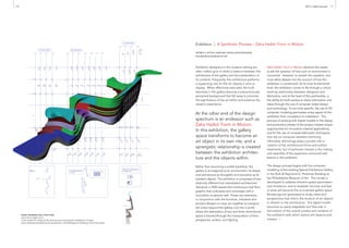
MODEL DRAWINGS (WALL STRUCTURE)
ASSOCIATED FABRICATION
Color-coded 3D image of the wall structure showing the breakdown of parts;
piece drawing representing the production methodology and labeling of the foam parts
2. As the design phase moves into production, the
working digital model allows for vital discussions
between designers and fabricators regarding the
building of architectural components. In this case,
the wall structure has numerous, often conflicting
requirements. The forms must be very light, yet self-
supporting. They must cantilever and span distances
with minimal support and anchoring. They must
also be small enough to fit into the gallery through
existing doorways, but large enough to minimize
installation time in situ. Finally, the forms must be
robust enough to survive transportation, and they
must be affordable to accommodate an exhibition
budget. With these requirements, the fabricators
settle on a somewhat unorthodox material for
construction: expanded polystyrene foam (EPS).
For its many applications, EPS foam is less commonly
used as a structural and sculptural element in an
exhibition setting. The contours of the sculptural
wall are made up of large foam blocks at varying
thicknesses. The same digital files that enabled
designers to study and develop the exhibition layout
are reinterpreted to create cutting templates for the
vast assortment of curvilinear forms. Once these
piece drawings are produced, the foam is cut using a
Computer Numerical Control (CNC) hot wire cutter.
Through computer assisted machining, each piece is
generated to the exact size and proportion
specified by the designers. Then, through
meticulous attention to labeling and registration,
the cut foam pieces are glued together in larger
chunks, coated with a urethane hardener, pre-
finished and sized appropriately for transportation
and installation in the gallery. Once on site, the
pieces fit together like a giant puzzle with
oversized finger joints that disappear to create
what appears to be a single stacked and
continuous form. Through this method of
machining and pre-fabrication, the seemingly
infeasible sculptural element is constructed,
installed and finished in a matter of days.
While technology helps bring this type of intricate
exhibition to fruition, I would like to acknowledge
the tremendous amount of work put forth by many
individuals with respect to the design, fabrication,
and coordination of Zaha Hadid: Form in Motion.
On behalf of the Philadelphia Museum of Art staff
in collaboration with Zaha Hadid Architects and
Associated Fabrication on this project, we would
like to thank all of the designers and fabricators
involved for their diligent efforts that have result-
ed in a truly unique and inspiring exhibition. JS
Installation View of Zaha Hadid: Form in Motion
at the Philadelphia Museum of Art