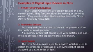
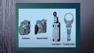
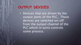
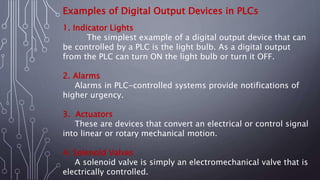
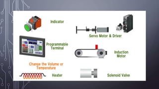
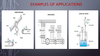
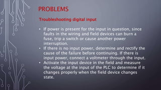
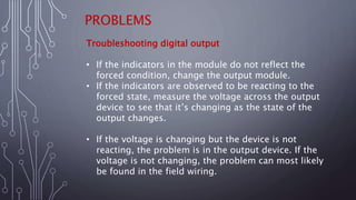
2. INPUT DEVICES
• The term sensor is used
for an input device that
provides a usable output
in response to a specified
physical input
(Thermocouple).
3. Examples of Digital Input Devices in PLCs
1. START/STOP Push Buttons
Start/Stop Pushbuttons are usually located in a PLC
control panel. They function either by making or breaking
contact. They are thus classified as either Normally Closed
(NC) or Normally Open (NO).
2. Proximity Sensors
Proximity switches are used to detect the presence of an
item without making contact.
A proximity switch that can be used with metallic and non-
metallic objects is the capacitive proximity switch.
3. Limit Switch
The term limit switch is used for a switch which is used to
detect the presence or passage of a moving part. It can be
actuated by a cam, roller or lever.
4.
5. OUTPUT DEVICES
• Devices that are driven by the
output ports of the PLC,. These
devices are switched on/off
from the output channel of the
PLC which in turns controls
some process.
6. Examples of Digital Output Devices in PLCs
1. Indicator Lights
The simplest example of a digital output device that can
be controlled by a PLC is the light bulb. As a digital output
from the PLC can turn ON the light bulb or turn it OFF.
2. Alarms
Alarms in PLC-controlled systems provide notifications of
higher urgency.
3. Actuators
These are devices that convert an electrical or control signal
into linear or rotary mechanical motion.
4. Solenoid Valves
A solenoid valve is simply an electromechanical valve that is
electrically controlled.
9. PROBLEMS
Troubleshooting digital input
• If power is present for the input in question, since
faults in the wiring and field devices can burn a
fuse, trip a switch or cause another power
interruption.
• If there is no input power, determine and rectify the
cause of the failure before continuing. If there is
input power, connect a voltmeter through the input.
• Activate the input device in the field and measure
the voltage at the input of the PLC to determine if it
changes properly when the field device changes
state.
10. PROBLEMS
Troubleshooting digital output
• If the indicators in the module do not reflect the
forced condition, change the output module.
• If the indicators are observed to be reacting to the
forced state, measure the voltage across the output
device to see that it’s changing as the state of the
output changes.
• If the voltage is changing but the device is not
reacting, the problem is in the output device. If the
voltage is not changing, the problem can most likely
be found in the field wiring.