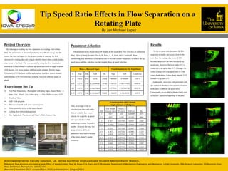
SlideShare a Scribd company logo
1 of 1
Download to read offline
Project Overview
By reducing or avoiding the flow separation on a rotating wind turbine
blade, the performance is increased producing more lift and energy. For this
reason, the short-term goal for this project consists in studying the flow
structure of a rotating plate and trying to identify when is there a stable leading
edge vortex in the blade. This was executed by using dye flow visualization
methods in a water channel at different tip speed ratios with an angle of attack
of 30 degrees. For future studies, with the results obtained, Particle Image
Velocimetry (PIV) methods will be implemented to achieve a more detailed
understanding of the flow structure, including tests with different angles of
attack.
Experiment Set Up
 Test Plate Dimensions - Rectangular with sharp edges, Aspect Ratio – 4,
Span – 4 in., chord – 1 in., radius to tip – 4.25in, Radius to root – 0.25.
 Brushless Motor
 Galil Tools program
 Waterproof nacelle with water suction system.
 Motor assembly on top of the water channel.
 Lighting from bottom and upstream
 Dye Application: Fluoriscine and Elmer’s Multi-Purpose Glue
Parameter Selection
The parameters were chosen based off the data in the research of Flow Structure on a Rotating
Wing: Effect of Steady Incident Flow by M. Bross, C. A. Ozen, and D. Rockwell. When
transforming their parameters to the aspect ratio of the plate used in this project, to achieve the tip
speed ratios and flow velocities, we had to apply these tip speed velocities.
Then, an average of the tip
velocities was taken and with a
MatLab code the free stream
velocity for a specific tip speed
ratio was calculated while
maintaining a similar Reynold’s
number. However, for very low
tip speed ratios, different
parameters were used to because
of the water channel’s pump
limitations.
Bross & Rockwell Paper Transformations to Our Experiment
U Vtip TSR Veff Re Vtip Veff Counts/sec
0 0.618 N/A 0.618 23430 0.805689 0.805689 2387.4
0.05 0.279 5.58 0.28344488 10766 0.385523 0.388751828 4569.49
0.1 0.279 2.79 0.296379824 11257 0.373955 0.387094746 4432.38
0.15 0.279 1.86 0.316766475 12030 0.366819 0.39630314 4347.8
Experimentation with Constant
Angle of Attack of 30 degrees
TSR
Free Stream
Velocity (m/s)
Velocity at
Tip (m/s) Veff m/s Re
1 0.07 0.07 0.09899 2879
1.5 0.07 0.105 0.1262 3669
2 0.1877 0.37543 0.4197 12207
2.5 0.1502 0.37543 0.4044 11759
3 0.1251 0.37543 0.3957 11508
3.5 0.1073 0.37543 0.3905 11355
4 0.0939 0.37543 0.387 11254
4.5 0.0834 0.37543 0.3846 11184
5 0.0751 0.37543 0.3829 11134
5.5 0.0683 0.37543 0.3816 11097
6 0.0626 0.37543 0.3806 11068
7 0.0536 0.37543 0.3792 11029
Results
As the tip speed ratio increases, the flow
separation is smaller and occurs closer to the
root. Also, the leading edge vortex (LEV)
becomes larger with the same increase in tip
speed ratio. However, the most stable LEV is
found with a tip speed ratio of 5. Although, the
vortex is larger with a tip speed ratio of 7, the
vortex sheds almost 3 times faster than the LEV
formed at a tip ratio of 5.
Additionally, more tests with performed with
dye applied at chordwise and spanwise locations
in the plate at different tip speed ratios.
Consequently we are able to obtain a better view
of the flow separation happening in the plate.
Tip Speed Ratio Effects in Flow Separation on a
Rotating Plate
Acknowledgments: Faculty Sponsor, Dr. James Buchholz and Graduate Student Mentor Kevin Wabick.
Reference: Flow structure on a rotating wing: Effect of steady incident flow: M. Bross, C. A. Ozen, and D. Rockwella. Department of Mechanical Engineering and Mechanics, Lehigh University, 356 Packard Laboratory, 19 Memorial Drive
West, Bethlehem, Pennsylvania 18015, USA
(Received 2 November 2012; accepted 8 July 2013; published online 1 August 2013)
By Jan Michael Lopez

More Related Content

What's hot

Calibration of Flow Sensors by Nabeel Ehmed
Calibration of Flow Sensors by Nabeel EhmedCalibration of Flow Sensors by Nabeel Ehmed
Calibration of Flow Sensors by Nabeel EhmedNabeel Ehmed
 
DEVELOPMENT OF GENERALIZED SPECIFIC ENERGY AND SPECIFIC FORCE CURVES
DEVELOPMENT OF GENERALIZED SPECIFIC ENERGY AND SPECIFIC FORCE CURVESDEVELOPMENT OF GENERALIZED SPECIFIC ENERGY AND SPECIFIC FORCE CURVES
DEVELOPMENT OF GENERALIZED SPECIFIC ENERGY AND SPECIFIC FORCE CURVESEngr. Md. Arafat Hossain Jibon
 
REU Wind Energy Luncheon Presentation
REU Wind Energy Luncheon PresentationREU Wind Energy Luncheon Presentation
REU Wind Energy Luncheon PresentationGabriel Col
 
FSI-based Overflow Assessment of Liquid Storage Tanks
FSI-based Overflow Assessment of Liquid Storage TanksFSI-based Overflow Assessment of Liquid Storage Tanks
FSI-based Overflow Assessment of Liquid Storage TanksIRJET Journal
 
Electro magnetic flow meter
Electro magnetic flow meterElectro magnetic flow meter
Electro magnetic flow meterAbhinav Bijapur
 
Field methods final project
Field methods final projectField methods final project
Field methods final projectQisKIA
 
ROTAMETER: ITS CONSTRUCTION AND WORKING
ROTAMETER: ITS CONSTRUCTION AND WORKINGROTAMETER: ITS CONSTRUCTION AND WORKING
ROTAMETER: ITS CONSTRUCTION AND WORKINGSammisla R Nayak
 
DSD-INT 2014 - Symposium Next Generation Hydro Software (NGHS) - Global tide ...
DSD-INT 2014 - Symposium Next Generation Hydro Software (NGHS) - Global tide ...DSD-INT 2014 - Symposium Next Generation Hydro Software (NGHS) - Global tide ...
DSD-INT 2014 - Symposium Next Generation Hydro Software (NGHS) - Global tide ...Deltares
 
DSD-INT 2021 Application Of Arabian Gulf Community Model to Dubai Coastal Wat...
DSD-INT 2021 Application Of Arabian Gulf Community Model to Dubai Coastal Wat...DSD-INT 2021 Application Of Arabian Gulf Community Model to Dubai Coastal Wat...
DSD-INT 2021 Application Of Arabian Gulf Community Model to Dubai Coastal Wat...Deltares
 
MicroHydro Design Project REPORT
MicroHydro Design Project REPORTMicroHydro Design Project REPORT
MicroHydro Design Project REPORTMichael Clarke
 
Sap flow: Calcium, and what about N and P?
Sap flow: Calcium, and what about N and P?Sap flow: Calcium, and what about N and P?
Sap flow: Calcium, and what about N and P?melnhe
 
Comparison of satellite imagery based ice drift with wind model for the Caspi...
Comparison of satellite imagery based ice drift with wind model for the Caspi...Comparison of satellite imagery based ice drift with wind model for the Caspi...
Comparison of satellite imagery based ice drift with wind model for the Caspi...Sergey Vernyayev
 
flow_through_linear_weir in analysis of the
flow_through_linear_weir in analysis of the flow_through_linear_weir in analysis of the
flow_through_linear_weir in analysis of the huamrajak
 
Hydrodynamic Analysis of Baral river
Hydrodynamic Analysis of Baral riverHydrodynamic Analysis of Baral river
Hydrodynamic Analysis of Baral riverKhushnuma Wasim
 
IAHR2015 - Characterization of hydraulic structures by means of numerical sim...
IAHR2015 - Characterization of hydraulic structures by means of numerical sim...IAHR2015 - Characterization of hydraulic structures by means of numerical sim...
IAHR2015 - Characterization of hydraulic structures by means of numerical sim...Deltares
 
3.3 IUKWC Workshop Freshwater EO - Marian Scott - Jun17
3.3 IUKWC Workshop Freshwater EO - Marian Scott - Jun173.3 IUKWC Workshop Freshwater EO - Marian Scott - Jun17
3.3 IUKWC Workshop Freshwater EO - Marian Scott - Jun17India UK Water Centre (IUKWC)
 

What's hot (20)

Flow standards
Flow standards Flow standards
Flow standards
 
Calibration of Flow Sensors by Nabeel Ehmed
Calibration of Flow Sensors by Nabeel EhmedCalibration of Flow Sensors by Nabeel Ehmed
Calibration of Flow Sensors by Nabeel Ehmed
 
DEVELOPMENT OF GENERALIZED SPECIFIC ENERGY AND SPECIFIC FORCE CURVES
DEVELOPMENT OF GENERALIZED SPECIFIC ENERGY AND SPECIFIC FORCE CURVESDEVELOPMENT OF GENERALIZED SPECIFIC ENERGY AND SPECIFIC FORCE CURVES
DEVELOPMENT OF GENERALIZED SPECIFIC ENERGY AND SPECIFIC FORCE CURVES
 
REU Wind Energy Luncheon Presentation
REU Wind Energy Luncheon PresentationREU Wind Energy Luncheon Presentation
REU Wind Energy Luncheon Presentation
 
FSI-based Overflow Assessment of Liquid Storage Tanks
FSI-based Overflow Assessment of Liquid Storage TanksFSI-based Overflow Assessment of Liquid Storage Tanks
FSI-based Overflow Assessment of Liquid Storage Tanks
 
Electro magnetic flow meter
Electro magnetic flow meterElectro magnetic flow meter
Electro magnetic flow meter
 
Field methods final project
Field methods final projectField methods final project
Field methods final project
 
ROTAMETER: ITS CONSTRUCTION AND WORKING
ROTAMETER: ITS CONSTRUCTION AND WORKINGROTAMETER: ITS CONSTRUCTION AND WORKING
ROTAMETER: ITS CONSTRUCTION AND WORKING
 
DSD-INT 2014 - Symposium Next Generation Hydro Software (NGHS) - Global tide ...
DSD-INT 2014 - Symposium Next Generation Hydro Software (NGHS) - Global tide ...DSD-INT 2014 - Symposium Next Generation Hydro Software (NGHS) - Global tide ...
DSD-INT 2014 - Symposium Next Generation Hydro Software (NGHS) - Global tide ...
 
DSD-INT 2021 Application Of Arabian Gulf Community Model to Dubai Coastal Wat...
DSD-INT 2021 Application Of Arabian Gulf Community Model to Dubai Coastal Wat...DSD-INT 2021 Application Of Arabian Gulf Community Model to Dubai Coastal Wat...
DSD-INT 2021 Application Of Arabian Gulf Community Model to Dubai Coastal Wat...
 
Soil and Water Engineering 04
Soil and Water Engineering 04Soil and Water Engineering 04
Soil and Water Engineering 04
 
MicroHydro Design Project REPORT
MicroHydro Design Project REPORTMicroHydro Design Project REPORT
MicroHydro Design Project REPORT
 
Sap flow: Calcium, and what about N and P?
Sap flow: Calcium, and what about N and P?Sap flow: Calcium, and what about N and P?
Sap flow: Calcium, and what about N and P?
 
Comparison of satellite imagery based ice drift with wind model for the Caspi...
Comparison of satellite imagery based ice drift with wind model for the Caspi...Comparison of satellite imagery based ice drift with wind model for the Caspi...
Comparison of satellite imagery based ice drift with wind model for the Caspi...
 
flow_through_linear_weir in analysis of the
flow_through_linear_weir in analysis of the flow_through_linear_weir in analysis of the
flow_through_linear_weir in analysis of the
 
various flow meter
various flow metervarious flow meter
various flow meter
 
Hydrodynamic Analysis of Baral river
Hydrodynamic Analysis of Baral riverHydrodynamic Analysis of Baral river
Hydrodynamic Analysis of Baral river
 
IAHR2015 - Characterization of hydraulic structures by means of numerical sim...
IAHR2015 - Characterization of hydraulic structures by means of numerical sim...IAHR2015 - Characterization of hydraulic structures by means of numerical sim...
IAHR2015 - Characterization of hydraulic structures by means of numerical sim...
 
3.3 IUKWC Workshop Freshwater EO - Marian Scott - Jun17
3.3 IUKWC Workshop Freshwater EO - Marian Scott - Jun173.3 IUKWC Workshop Freshwater EO - Marian Scott - Jun17
3.3 IUKWC Workshop Freshwater EO - Marian Scott - Jun17
 
Weather Windows
Weather WindowsWeather Windows
Weather Windows
 

Similar to Poster

A study on Nonlinear flow through an orifice meter
A study on Nonlinear flow through an orifice meterA study on Nonlinear flow through an orifice meter
A study on Nonlinear flow through an orifice metersunnynita
 
Hooman_Rezaei_asme_paper2
Hooman_Rezaei_asme_paper2Hooman_Rezaei_asme_paper2
Hooman_Rezaei_asme_paper2rezaeiho
 
Heim_Ghandhi_JAutoEng_2011
Heim_Ghandhi_JAutoEng_2011Heim_Ghandhi_JAutoEng_2011
Heim_Ghandhi_JAutoEng_2011Douglas Heim
 
IRJET- Investigation of Fluid Flow Characteristics for the Forced Convect...
IRJET-  	  Investigation of Fluid Flow Characteristics for the Forced Convect...IRJET-  	  Investigation of Fluid Flow Characteristics for the Forced Convect...
IRJET- Investigation of Fluid Flow Characteristics for the Forced Convect...IRJET Journal
 
Mechanical fluid , Broad Crested Wrir
Mechanical fluid , Broad Crested WrirMechanical fluid , Broad Crested Wrir
Mechanical fluid , Broad Crested WrirHusseinAli272
 
Investigation of Flow Parameters and Structural Analysis of Y-Duct
Investigation of Flow Parameters and Structural Analysis of Y-DuctInvestigation of Flow Parameters and Structural Analysis of Y-Duct
Investigation of Flow Parameters and Structural Analysis of Y-DuctIRJET Journal
 
Spinner velosity tool
Spinner velosity toolSpinner velosity tool
Spinner velosity toolArash Nasiri
 
Studies on impact of inlet viscosity ratio, decay rate & length scales in a c...
Studies on impact of inlet viscosity ratio, decay rate & length scales in a c...Studies on impact of inlet viscosity ratio, decay rate & length scales in a c...
Studies on impact of inlet viscosity ratio, decay rate & length scales in a c...QuEST Global
 
Performance Analysis of savonius hydro turbine using CFD simulation
Performance Analysis of savonius hydro turbine using CFD simulationPerformance Analysis of savonius hydro turbine using CFD simulation
Performance Analysis of savonius hydro turbine using CFD simulationIRJET Journal
 
IRJET- A Research Paper on Analysis of De-Laval Nozzle on Ansys Workbench
IRJET-  	  A Research Paper on Analysis of De-Laval Nozzle on Ansys WorkbenchIRJET-  	  A Research Paper on Analysis of De-Laval Nozzle on Ansys Workbench
IRJET- A Research Paper on Analysis of De-Laval Nozzle on Ansys WorkbenchIRJET Journal
 
lab 4 requermenrt.pdfMECH202 – Fluid Mechanics – 2015 Lab .docx
lab 4 requermenrt.pdfMECH202 – Fluid Mechanics – 2015 Lab .docxlab 4 requermenrt.pdfMECH202 – Fluid Mechanics – 2015 Lab .docx
lab 4 requermenrt.pdfMECH202 – Fluid Mechanics – 2015 Lab .docxDIPESH30
 
Final course project report
Final course project reportFinal course project report
Final course project reportKaggwa Abdul
 
Acondicionador sistemas de control
Acondicionador sistemas de controlAcondicionador sistemas de control
Acondicionador sistemas de controloms242000
 
Effect of Turbulence Model in Numerical Simulation of Single Round Jet at Low...
Effect of Turbulence Model in Numerical Simulation of Single Round Jet at Low...Effect of Turbulence Model in Numerical Simulation of Single Round Jet at Low...
Effect of Turbulence Model in Numerical Simulation of Single Round Jet at Low...ijceronline
 
Flow separation control using plasma vortex generators
Flow separation control using plasma vortex generatorsFlow separation control using plasma vortex generators
Flow separation control using plasma vortex generatorsKamran Ashraf
 

Similar to Poster (20)

A study on Nonlinear flow through an orifice meter
A study on Nonlinear flow through an orifice meterA study on Nonlinear flow through an orifice meter
A study on Nonlinear flow through an orifice meter
 
Hooman_Rezaei_asme_paper2
Hooman_Rezaei_asme_paper2Hooman_Rezaei_asme_paper2
Hooman_Rezaei_asme_paper2
 
Heim_Ghandhi_JAutoEng_2011
Heim_Ghandhi_JAutoEng_2011Heim_Ghandhi_JAutoEng_2011
Heim_Ghandhi_JAutoEng_2011
 
IRJET- Investigation of Fluid Flow Characteristics for the Forced Convect...
IRJET-  	  Investigation of Fluid Flow Characteristics for the Forced Convect...IRJET-  	  Investigation of Fluid Flow Characteristics for the Forced Convect...
IRJET- Investigation of Fluid Flow Characteristics for the Forced Convect...
 
Mechanical fluid , Broad Crested Wrir
Mechanical fluid , Broad Crested WrirMechanical fluid , Broad Crested Wrir
Mechanical fluid , Broad Crested Wrir
 
H013164652
H013164652H013164652
H013164652
 
HarpreetMatharoo_IITDelhi
HarpreetMatharoo_IITDelhiHarpreetMatharoo_IITDelhi
HarpreetMatharoo_IITDelhi
 
Investigation of Flow Parameters and Structural Analysis of Y-Duct
Investigation of Flow Parameters and Structural Analysis of Y-DuctInvestigation of Flow Parameters and Structural Analysis of Y-Duct
Investigation of Flow Parameters and Structural Analysis of Y-Duct
 
Spinner velosity tool
Spinner velosity toolSpinner velosity tool
Spinner velosity tool
 
Studies on impact of inlet viscosity ratio, decay rate & length scales in a c...
Studies on impact of inlet viscosity ratio, decay rate & length scales in a c...Studies on impact of inlet viscosity ratio, decay rate & length scales in a c...
Studies on impact of inlet viscosity ratio, decay rate & length scales in a c...
 
Performance Analysis of savonius hydro turbine using CFD simulation
Performance Analysis of savonius hydro turbine using CFD simulationPerformance Analysis of savonius hydro turbine using CFD simulation
Performance Analysis of savonius hydro turbine using CFD simulation
 
IRJET- A Research Paper on Analysis of De-Laval Nozzle on Ansys Workbench
IRJET-  	  A Research Paper on Analysis of De-Laval Nozzle on Ansys WorkbenchIRJET-  	  A Research Paper on Analysis of De-Laval Nozzle on Ansys Workbench
IRJET- A Research Paper on Analysis of De-Laval Nozzle on Ansys Workbench
 
Lg3420362048
Lg3420362048Lg3420362048
Lg3420362048
 
lab 4 requermenrt.pdfMECH202 – Fluid Mechanics – 2015 Lab .docx
lab 4 requermenrt.pdfMECH202 – Fluid Mechanics – 2015 Lab .docxlab 4 requermenrt.pdfMECH202 – Fluid Mechanics – 2015 Lab .docx
lab 4 requermenrt.pdfMECH202 – Fluid Mechanics – 2015 Lab .docx
 
Final course project report
Final course project reportFinal course project report
Final course project report
 
Acondicionador sistemas de control
Acondicionador sistemas de controlAcondicionador sistemas de control
Acondicionador sistemas de control
 
Effect of Turbulence Model in Numerical Simulation of Single Round Jet at Low...
Effect of Turbulence Model in Numerical Simulation of Single Round Jet at Low...Effect of Turbulence Model in Numerical Simulation of Single Round Jet at Low...
Effect of Turbulence Model in Numerical Simulation of Single Round Jet at Low...
 
TB03.pdf
TB03.pdfTB03.pdf
TB03.pdf
 
Flow separation control using plasma vortex generators
Flow separation control using plasma vortex generatorsFlow separation control using plasma vortex generators
Flow separation control using plasma vortex generators
 
B012410616
B012410616B012410616
B012410616
 

Poster

  • 1. Project Overview By reducing or avoiding the flow separation on a rotating wind turbine blade, the performance is increased producing more lift and energy. For this reason, the short-term goal for this project consists in studying the flow structure of a rotating plate and trying to identify when is there a stable leading edge vortex in the blade. This was executed by using dye flow visualization methods in a water channel at different tip speed ratios with an angle of attack of 30 degrees. For future studies, with the results obtained, Particle Image Velocimetry (PIV) methods will be implemented to achieve a more detailed understanding of the flow structure, including tests with different angles of attack. Experiment Set Up  Test Plate Dimensions - Rectangular with sharp edges, Aspect Ratio – 4, Span – 4 in., chord – 1 in., radius to tip – 4.25in, Radius to root – 0.25.  Brushless Motor  Galil Tools program  Waterproof nacelle with water suction system.  Motor assembly on top of the water channel.  Lighting from bottom and upstream  Dye Application: Fluoriscine and Elmer’s Multi-Purpose Glue Parameter Selection The parameters were chosen based off the data in the research of Flow Structure on a Rotating Wing: Effect of Steady Incident Flow by M. Bross, C. A. Ozen, and D. Rockwell. When transforming their parameters to the aspect ratio of the plate used in this project, to achieve the tip speed ratios and flow velocities, we had to apply these tip speed velocities. Then, an average of the tip velocities was taken and with a MatLab code the free stream velocity for a specific tip speed ratio was calculated while maintaining a similar Reynold’s number. However, for very low tip speed ratios, different parameters were used to because of the water channel’s pump limitations. Bross & Rockwell Paper Transformations to Our Experiment U Vtip TSR Veff Re Vtip Veff Counts/sec 0 0.618 N/A 0.618 23430 0.805689 0.805689 2387.4 0.05 0.279 5.58 0.28344488 10766 0.385523 0.388751828 4569.49 0.1 0.279 2.79 0.296379824 11257 0.373955 0.387094746 4432.38 0.15 0.279 1.86 0.316766475 12030 0.366819 0.39630314 4347.8 Experimentation with Constant Angle of Attack of 30 degrees TSR Free Stream Velocity (m/s) Velocity at Tip (m/s) Veff m/s Re 1 0.07 0.07 0.09899 2879 1.5 0.07 0.105 0.1262 3669 2 0.1877 0.37543 0.4197 12207 2.5 0.1502 0.37543 0.4044 11759 3 0.1251 0.37543 0.3957 11508 3.5 0.1073 0.37543 0.3905 11355 4 0.0939 0.37543 0.387 11254 4.5 0.0834 0.37543 0.3846 11184 5 0.0751 0.37543 0.3829 11134 5.5 0.0683 0.37543 0.3816 11097 6 0.0626 0.37543 0.3806 11068 7 0.0536 0.37543 0.3792 11029 Results As the tip speed ratio increases, the flow separation is smaller and occurs closer to the root. Also, the leading edge vortex (LEV) becomes larger with the same increase in tip speed ratio. However, the most stable LEV is found with a tip speed ratio of 5. Although, the vortex is larger with a tip speed ratio of 7, the vortex sheds almost 3 times faster than the LEV formed at a tip ratio of 5. Additionally, more tests with performed with dye applied at chordwise and spanwise locations in the plate at different tip speed ratios. Consequently we are able to obtain a better view of the flow separation happening in the plate. Tip Speed Ratio Effects in Flow Separation on a Rotating Plate Acknowledgments: Faculty Sponsor, Dr. James Buchholz and Graduate Student Mentor Kevin Wabick. Reference: Flow structure on a rotating wing: Effect of steady incident flow: M. Bross, C. A. Ozen, and D. Rockwella. Department of Mechanical Engineering and Mechanics, Lehigh University, 356 Packard Laboratory, 19 Memorial Drive West, Bethlehem, Pennsylvania 18015, USA (Received 2 November 2012; accepted 8 July 2013; published online 1 August 2013) By Jan Michael Lopez