
Recommended
Recommended
More Related Content
What's hot
What's hot (10)
Similar to Joint reliance features quality products withstand pressure
Similar to Joint reliance features quality products withstand pressure (20)
More from Ir. Hadi Budiman
Joint reliance features quality products withstand pressure
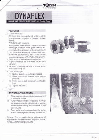
- 1. A joint reliance a a FEATURES Quality Products All joints are manufactured under a strict quality assurance system of lS09002 certified factory" Withstand high pressure An excellent moulding technique combined with tough chemical fibres gives DYNAFLEX ar! outstanding pressure withstandability. lt carr ./ithstand a bursting pressure of over 4.90MFa {50kgtlcm2l and a maximum operating pressure of 1.47MPa {1Skgf/cmz}" Fit for suction and delivery (discharge) Highly effective to eliminate sound and vibration. Excellent in resisting the effects of heat, water arr'C weathering, etc. Other advantages (1) Neither gasket nor packing is needed. 2) N/ass production nrakes lower prices possible. (3) Fit for uses in both expansion and flexible loint. (4) A good insulator" - d.{/a!! , TVPICAL AP".PLICAilONS,,,, : , ':' ', 1,, {l ) lVater piping systems of building equipment in industrial plants. (2) Pump lines and turbine lines used in power generating plants, shipbuilding yards, industrial nnachinery and universal pump blowers, etc. (3) Feed water and drainage lines for water works, sewerage and sanitary system, etc. Others : This connector has a wide range of applications in waste water disposal plants, rnines and chemical plants, eic.
- 2. r "'-::F- T@zEt{ r A joint reliance NOTES 1. Always check for the suitability of operating conditions when install joints. 2. When installjoints, check for cracks on the rubber paft, especially after a long period of storage. 3. Do not installjoints at full'limits of all allowable movements simultaneously. 4" ln case of joint displacement, be awared of external objects (especially those with sharp edges) which may damage the rubber body. 5. Keep away from heating source when install. Cover joints with protection sheet to f ree ff. ,. any harm of spark resulted from welding, pre-arcing and grinding nearthe spot of joint installation. 6. lf oils, fats, organic solvent, acid or alkali are adhered, wipe them off quickly. 7. Avoid direct exposure of sunlight in case of outdoor piping to prevent aging and deterioration of rubber. 8. During joint installation, fix pipes before and behind joints to avoid elongation to joints due to water pressure. ln case fixing of pipes is not possible, conti'ol unit is required to prevent the joints from elongation. 'r.,.,''".:ul "'', .ld:':. .,3.,,.,.. . -,f: Specifications are subject to change without prior notice TOZEN SANGYO CO., LTD B-4, Asahi, Yoshikawa-shi, Saitama-ken 342 Japan Tele. : (0489) 93-1035 Fax : (0489) 93-1018 DF-1101
- 3. w *il-f@Zgru A joint reliance A L.LOWAB LI MOVEMENTS..{N OPE RATION T.M. = Transv'-j,rse ldo,yement A.C. = Axial Compression A.E. - Axial Elongation ,A.M. = Angular Movement Although allowable movements are given, no allowance for elongation is recomrnended when installing joint. 3) lnstall joint following the given allowable dimensions. :, ,*pil,.#S lnformation in the above table are for single displacement only. ln case of complex displacement, follow the below expression. A.E. _ E. A.A.M. _ A.M. c. EL (c) = {A.EL(C)} X oa X A.A.M. cFt A. EL A.E. E. A.A.M. A.M. 1) 2) {C, -- Cor:recJ ElongUtrran {Cor4nreSstrn) (C) = Allowable Elongation (Compression) = AllowableEccentricity = Eccentricity = Allowable Angular Movement = Angular fvlovement A.M, (')rnih ,ln. 1.1/4 b 5 8 li) 40 1.112 B 5 8 15 50 2 I b 10 t5 65 2.1/2 10 7 13 1E BO 3 11 8 14 t5 100 4 12 10 1B 15 tz3 5 12 11 19 1e 150 6 14 12 io 15 200 B 22 14 25 t5 250 10 22 14 15 300 12 16 25 t5 DF-1101
- 4. v-- f@Z gffi *u*u"**u*'***,,*'*''siffit*seais#F*i'41'.i A joint reliance f:.air'"rilr-:jr:i,..- : .-j:;-.- j, :r r- _i;,ffi;::g STRUCTU RE DIMENSIONS 0{: ! rl,3 'l-5 t t-( l't5 rfn t"rf .l:e6 %' &ss ,'Rge trn /g OPERATING CONDITIONS t-,lse DYNAFI-EX under conditions specified in the below graph. Normal operating pressure : 32-100 : Max. 1 .47MFa {1Skgf/cm2 } in normal temperature 125-300 : Max. 1.1BMPa {12kgf/cmei in normal temperature Operating temperature : -20 to +70sG Bursting pressure : 32-100 : over 4.90MPa {50kgf/cm2} in normal temperature 125-300 : over 3.43MPa {35kgf/cm2} in normal tempeirature 100 80 70 60 ilo 2A 0 -20 -{.006 0 0.,19 0.98 t-t€ t.47 t.96 {-o5o"EHd (sl (10} ft2l tlsl {2ol UeX wOnrCWC pRESs'uREtMPrl{trcu] . Applicable fluids : water, warm water, sea water, weak acids, alkalines, etc. e E] k r'l fn F o z t4 : No. Part Material 1 Flange Mild Steel z Reinforcing Ring Carbon Steel lnner Rubber Synthetic Rubber 4 Outer Rubber Synthetic Rubber 5 Beinforcing Cord Synthetic Fibre mm in. az (1 " 1/4) 40 (1.1/2) 50 t2) 65 {2.1t2j 80 (3) 100 (4) 125 (5) 150 (6) 200 (B) 250 (10) 300 (12) B o D PLY L 3 95 3 o( 3 iUo 4 1-1i. 4 i2R 4 150 F. 165 6 180 h 190 8 230 I 245 aD1 76 76 86.5 r06 11B 146 1AO 212 264 324 372 @D2 40 40 50 60 72 100 125 I tn 200 250 300 DF-110'1