SlideShare a Scribd company logo
1 of 69
Download to read offline
Standard Pipe & Line Pipe
I
ITT Grinnell
C O N T E N T S
General Information	 3
Facilities	 8
Product Properties	 21
Comparative Specifications	 24
Pipe Tables	 41
Glossary	 65DAT			A		T	
disclaimer
all material contained in this publication is for general information only. this material should not, therefore, be used or relied upon
for any specific application without independent competent professional examination and verification of its accuracy, suitability
and applicability. anyone making use of the material does so at their own risk and assumes any and all liability resulting from such
use. ITT GrinnellProducts disclaims any and all expressed or implied warranties of merchantability and/or fitness for any general or
particular purpose. RA
2
General
InformationlIfooT	NT
			T			T			T								
GeneraL
inFOrmatiOn
ITT Grinnell employees are deeply committed to being
easy to do business with anywhere in the world. As an
industry-leading manufacturer, our focus is to offer the
widest range of products and to exceed your expectations for
on-time delivery, easy installation, performance and
operating efficiency.
Our Mission: To be the market leader in the development,
manufacture and worldwide sale of quality air moving and
control equipment with total commitment to the customer.
Our commitment to our customers is what drives our long-
standing sustainability practices. We continuously strive to
reduce energy usage and other production costs to ensure
competitive prices for you and ongoing business success. We
support the health, safety and training of our employees to
achieve the high quality product performance you expect
from ITT Grinnell — and deserve. And we take on the
industry’s most complex challenges by introducing
innovative new product solutions to meet your future needs.
3
TT		AR			TDA	T		TMAIITAIAI	T		IT	TMTTTI	AAI	I
Sizes and Grades
ITT Grinnell Products provides seamless and
electric resistance welded pipe in Od sizes
ranging from ۱/۲ inches to ٤۸ inches. a variety of
end finishes, lengths, grades and wall thicknesses
are available.
to ensure the absolute highest quality,
ITT Grinnell Products has implemented a Quality
management System in full compliance with aPi
Q1 and TUV , .ITT Grinnell Products maintains
aPi licenses to manufacture and monogram
products to aPi specifications 5Ct and 5L.
in addition, Fairfield tubular Operations,
Lorain tubular Operations, mcKeesport tubular
Operations and texas tubular Operations manu-
facturing facilities are all TUV certified.
a full line of aPi grades and proprietary grades
are produced to meet specialized customer
needs, including HiC-resistant pipe for use in H2
S
environments and pipe grades with superior
impact properties even under extremely cold
arctic conditions.
the steels of today are far more sophisticated
than metals of earlier eras. the addition of alloys,
plus an array of field-testing, lab-testing, melting,
casting and hot-rolling practices, along with
specialized heat treatments, have created steels
that are precisely crafted to meet and/or exceed
demanding product requirements. ITT Grinnell
innovative software applications calculate,
measure, test, record and analyze every aspect of
the modern steelmaking process.
at ITT Grinnell , we use cutting-edge
technology to manage every aspect of production.
real-time communication between control room
and machine operators allows for precise
regulation of each step of the process, from
charging furnaces with raw ingredients to
controlling temperatures, timing, alloying, flows,
testing and transport.
ITT Grinnell commitment to the tubular busi-
ness is even stronger today than it was when we
went into the business more than a century ago.
Upgrades to our facilities and investments in new
technology give us the latest tools to provide our
customers with consistent high-quality products.
Sizes and Grades Chart
Type of Pipe
Regular Mill Production
Size Range,
NPS
Size Range,
Inches
Wall Thickness
Range, Inches
Max. Length,
Feet
Seamless 1.5 - 26 1.900 - 26 OD 0.140 - 2.312 48
Electric Resistance Weld 2 - 20 2.375 - 20.000 OD 0.154 - 0.625 80
General
Information
4
General
Information
	 Grades of steel vary in chemical
composition from simple carbon 	
manganese to complex multi-element
micro-alloyed composition. Precise
control of compositions and manufactur-
ing processes allows for the manufacture
of tubular products with a wide variety
of properties and attributes. 			
	 When selecting the proper Material
Specification, Pipe Grade, ASTM Special
Requirement, API 5L Product Service
Level (PSL), API 5L Annex Requirement
or CSA Z245.1 Category or Service Group,
the end use and method of pipe fabrica-
tion should be considered. Various
practices are employed in all phases of
steel production, which determine the 		
type and quality of the finished product.
5
USS M1020 Plain End ERW Pipe for Water Well Applications
USS M1021 Plain End ERW Pipe for Use in Structural Applications
USS M1024 Seamless Mechanical Tubing in Sizes from NPS 2 thru 26
USS M1029 Plain End Seamless Pipe for Use in General Purpose Applications
USS M1400
Constructional Alloy Steel Seamless Mechanical Tubing – Grades USS “T-1”
Type A and USS “T-1” Type B
USS M1407 ERW Pipe NPS 8 thru 12 for Lift Devices
USS M1430 Seamless Steel Slurry Pipe - Grade USS 430
USS M1431 Seamless Slurry Pipe to be Heat Treated. Primarily for Mechanical Joining
USS M1470 Seamless Steel Pipe for Fabrication into Ordinary Welding Fittings
USS M1471 Seamless Steel Pipe for Fabrication into High-Strength Welding Fittings
USS M1475 Seamless Steel Pipe for Manufacture of Cold-Formed Fittings
USS M2430 ERW Pipe Intended for Transportation of Solids in Slurry Form
Pressure Determinations
Barlow’s Formula is commonly used to determine the following:
• Internal Pressure at Minimum Yield
• Ultimate Burst Pressure
• Maximum Allowable Operating Pressure, and
• Mill Hydrostatic Test Pressure
This formula is expressed as P = , where:
P	=	pressure, psig
t	 =	nominal wall thickness, inches
D	=	outside diameter, inches
S	=	allowable stress, psi
To illustrate, assume a seamless piping system 8-5/8” OD x 0.375” wall specified to API 5L Grade B
which has a specified minimum yield strength (SMYS) of 35,500 psi and a specified minimum tensile
strength (SMTS) of 60,200 psi.
Internal Pressure at Minimum Yield
S=SMYS (35,500 psi)
and
P= 	 =	 = 3,087 or 3,090 psig (rounded to nearest 10 psig)
2St
D
MT
ITT Grinnell material Standards
ITT Grinnell material standards are specifications not covered by a society, association or other
specify-ing body. the following includes the material standards used most frequently for tubular
applications.
2 (35,500) (0.375)
8.625
2St
D
General
Information
6
Ultimate Burst Pressure at Minimum Tensile
S = SMYS (60,200 psi)
and
P =	 =	 = 5,234.7 psig or 5,230 psig (rounded to nearest 10 psig)
Maximum Allowable Operating Pressure (MAOP)
S=SMYS (35,500 psi) reduced by a design factor, for example 0.72,
and
P = 	 =	 = 2,222.6 psig or 2,220 psig (rounded to nearest 10 psig)
Mill Hydrostatic Test Pressure
S=SMYS (35,500 psi) reduced by a factor depending on OD and grade (0.60 for 8-5/8” OD Grade B)
and
P =	 =	 = 1,852.2 psig or 1,850 psig (rounded to nearest 10 psig)
Some safety codes and regulatory agencies also assign a longitudinal joint factor to account for weld
efficiency. The more common are 0.85 for ERW pipe and 0.60 for CW pipe. Seamless pipe enjoys a joint
factor of 1.00. This means that some designers consider ERW pipe as 85 percent as efficient as seam-
less pipe and CW pipe only 60 percent as efficient for the same application. Therefore, for a given
application, ERW pipe would require a heavier wall than seamless pipe, and CW pipe, in turn, would
require a heavier wall than ERW pipe.
Distributors who stock pipe in a combination of seamless, ERW, and CW must exercise extreme care to
see that pipe with joint efficiency factors of 0.85 or 0.60 is not used on jobs which require pipe with a
joint factor of 1.00.
Wall Thickness
Barlow’s Formula is also useful in determining the wall thickness required for a piping system. To
illustrate, assume a piping system has been designed with the following criteria:	
1. A working pressure of 2,000 psig (P)	
2. The pipe to be used is 8-5/8” OD (D) specified to API 5L Grade B (SMYS = 35,500 psi)
Rearranging Barlow’s Formula to solve for wall thickness gives:
t =	 =	 = 0.243 wall
Wall thickness does not affect the outside diameter; only the inside diameter is affected. For example,
the outside diameter of a one-inch extra-strong piece of pipe compared with a one-inch standard
weight piece of pipe is identical; however, the inside diameter of the extra-strong is smaller than the
inside diameter of the standard weight because the wall thickness is greater in the extra-strong pipe.
2 (60,200) (0.375)
8.625
2St
D
2 (35,500 x 0.72) (0.375)
8.625
2St
D
2 (35,500 x 0.60) (0.375)
8.625
2St
D
(2,000) (8.625)
2 (35,500)
PD
2S
General
Information
7
FACILITIES
8
Fairfield, Alabama - 4-1/2” to 9-7/8” OD
Seamless Manufacturing Process
Cast Round Billets Rotary Piercing
Mill (RPM)
Round Reheating Mandrel Mill
Shell ReheatingCooling Bed Stretch Reducing
Mill
Batch Saws
NDT Inspection In-Process Storage
	 Fairfield Tubular Operations can produce 	
approximately 840,000 net tons of seamless
tubular products every year. The process begins
with solid steel rounds, or billets, being cut to a
specified length and sent through a walking-beam
reheat furnace, where temperatures reach nearly
2,300°F.
	The yellow rounds are turned into a tube shell
in mere seconds in the rotary piercing mill as the
preheated billets are cross-rolled between two
barrel-shaped rolls at a high speed.
	The seamless shells enter Fairfield’s seven-
stand mandrel mill, where they are rolled over a
retained mandrel to provide the needed OD size
and wall thickness for the next process. The
process is carefully monitored using a 	
state-of-the-art hot-wall measuring system.
	The shells are then reheated for final forming in 	
a 24-stand stretch-reducing mill, where outside
diameters are formed to customers’ exacting 	
specifications. Wall thickness is again verified 	
using a hot-wall measuring system.
	After being rotated and advanced on the 	
walking-beam cooling bed, the pipes are batch
cut and transferred to an in-process storage area, 	
where they are handled by computer-controlled
gantry cranes. 	
Manufacturing:	Seamless
OD Range:	 4-1/2” to 9-7/8”
Walls:	 0.205” to 1.200”
Lengths:	 SRL, DRL
Grades: 	ASTM A 106B/A53 B, API5L GRADE B, X42, X52, X60, X65, X70,
		ASTM A333, CSA Z245.1 Grades 241 thru 483
Cut-Off Facilities
Facilities
Facilities
9
Austenitizing
Furnace
Sizing MillHot Straightener
Quenching Unit Tempering
Furnace
Cooling Bed
Straightening
Hydrostatic
Testing
NDT Inspection
Facing and
Beveling
Final Inspection
	 From this in-process storage, pipe can be
delivered to one of three primary workstations:
heat treating, finishing or special pipe processing.
	Depending on grade, pipe might undergo
quenching and tempering to alter its micro-	
structure to improve strength or other properties.
Quenching and tempering controls hardness,
reduces brittleness, and brings the steel to 	
tensile and yield strengths required for the
specified grade.
	 Seamless pipe that has not been quenched and
tempered passes initially through a straightener
and then a non-destructive testing (NDT) unit.
(Q&T pipe goes directly to the NDT area.)
	Electromagnetic inspection (EMI) detects 	
longitudinal and transverse flaws as the pipe
moves though a set of coils. Ultrasonic testing is
used to verify wall thickness. Grade/composition
is verified on each pipe by eddy current. All pipe 	
is hydro-tested.
	 Finished pipe is weighed, measured, stenciled
with a unique identification, coated and loaded
onto rail cars for shipment to customers.
Facilities
Cut-Off Facilities
Heat 	
Treating
Finishing
10
McKeesport, Pennsylvania - 8-5/8” to 20” OD
Electric Resistance Weld Manufacturing Process
Coil Feed Ramp Fin Pass SectionFirst Forming
Section
High Frequency
Welder
Sizing Mill Seam NormalizerAir Cooling &
Water Cooling
Weld Seam
Ultrasonic
Inspection
Flying Cut-Off
	McKeesport Tubular Operations sits on the
original site of National Tube Works. McKeesport
has been making tubular products since the 1870s
and electric-resistance weld pipe since 1964.
Steel arrives at the facility in coils that are 	
unrolled, cut and welded into a continuous strip
before entering the mill.
	The strip steel passes through a series of
forming rolls, which transform the strip from flat
steel to a round pipe section. The fin pass section
of the mill finishes the rounding process and
contours the edges of the strip for seam welding.
	The high-frequency welder heats the edges of
the rolled strip to approximately 2,600°F. Pressure
rolls then squeeze the heated edges together to
form a fusion weld. The weld is inspected by an
ultrasonic non-destructive inspection unit.
	The pipe then enters the seam normalizer
where the weld area is heat treated as per API
specification to remove welding stresses and
produce a uniform normalized grain structure.
	The weld is cooled in air below transformation
temperature and then water-cooled to near
ambient before passing through the sizing mill,
where idler side-closing rolls straighten the pipe
and size it to the correct outside diameter.
	As the continuous length of pipe moves down 	
the mill, the flying cut-off cuts lengths of pipe
Manufacturing: 	Electric Resistance Weld
OD Range: 	 8-5/8” to 20”
Walls: 	 0.188” to 0.406”
Lengths:	 SRL 18’-22’; DRL 39’-45’; TRL 33’-65’; QRL 42’-80’ max
Grades: 	ASTM A53 B, API5L GRADE B, X42, X52, X60, X65, X70,
		ASTM A523 A (cable pipe), CSA Z245.1 Grades 241 thru 483
Facilities
11
Facilities
Final Inspection Cut-Off Facilities
Hydrostatic
Testing
Straightening
Finishing
Non-Destructive
Inspection
without interrupting the production line. Each
pipe is hydrostatic tested to ensure rated
strength and weld integrity under pressure. After
hydrotesting, any bow in the pipe is removed by
passage through a multi-stand straightener.
	The pipe enters the finishing floor where the
weld is ultrasonically inspected and the pipe is
examined by automated electromagnetic 	
inspection. After being cut to customer-specified
lengths, the pipe is finished and prepared for
shipment.
Facing and
Beveling
12
Lone Star, Texas - Mill No. 1 - 8-5/8” to 16” OD
Electric Resistance Weld Manufacturing Process
Full-Body
Normalize
Hot Reduce Cool	TTMNER	T		TT	T
ITT Grinnell Operations mill no. 1 manufactures
high-quality erW tubular products primarily for
the oil and gas industries.
Steel arrives at the facility in coils slit to
precise width before the manufacturing process
begins. the strip steel is uncoiled, leveled,
conveyed through a side trimmer, which shears
both edges to provide proper width and clean
surfaces for welding.
the strip then passes through a series of
forming rolls, which transform the coil from a flat
strip of steel to round pipe sections. the edges
of the strip are contoured for seam welding. the
weld is created by heat obtained from the pipe’s
resistance to the flow of electric current of the
circuit of which it is part, and by applied pressure
to form a forged weld. No filler metal is used in
the welding process.
	After the flash (metal extruded by the weld
process) is removed from the pipe’s inside and
outside surfaces, the pipe is cut to length by a
flying rotary cutoff. Weld integrity is checked by
ultrasonic test equipment in line behind each
welder.
	The pipe passes through a series of induction
heating furnaces where the entire pipe is heated
to temperatures above 1,650°F and allowed to 	
air cool. This full-body normalizing operation
Manufacturing: 	Electric Resistance Weld
OD Range: 	 8-5/8” to 16”
Walls: 	 0.250” to 0.562”
Lengths:	 SRL, DRL, TRL
Grades: 	ASTM A53 B, API5L GRADE B, X42, X52; Q&T Grades: X60, X65, X70, X80
Uncoil & LevelFlash
Trim
UST & Cut ER Weld Cage Mill Form Edge
Trim
Coil
Facilities
13
Straighten Hydrostatic TestBevel
Final Inspection
Weld USTPipeimage®
Full Body UST
Weigh, Measure,
Stencil & Ship
Upon Agreement Only
Facilities
produces uniform grain structure throughout the
entire pipe wall. The normalizing furnaces may
also heat the pipes for diameter reduction and a
more uniform finished product.
	After cooling, pipe is sized, straightened,
visually inspected, stenciled with the appropriate
identity and queued for finishing. Laboratory
tests confirm full compliance to specifications and
other mechanical property requirements before
the pipe is beveled, electromagnetically inspected
and hydrostatically tested.
	Multiple certifications are available.
NDT Inspection
Cut-Off Facilities
Facing and
Beveling
14
Lone Star, Texas - Mill No. 2 - 2-3/8” to 6-5/8” OD
Electric Resistance Weld Manufacturing Process
Uncoil & LevelFlash
Trim
UST & Cut ER Weld Form Edge
Trim
Full-Body
Normalize
Hot Stretch
Reduction
Cool
Coil	TTMNER	T	TTTN
ITT Grinnell Operations mill no. 2 manufactures
high-quality erW tubular products primarily for
the oil and gas industries.
Steel arrives in coils slit to precise width. the
strip steel is uncoiled, leveled, conveyed through
a side trimmer, which shears both edges to pro-
vide proper width and clean surfaces for welding.
the strip then passes through a series of
forming rolls, which transform the coil from a flat
strip of steel to round pipe sections. the edges of
the strip are contoured for seam welding. the
weld is created by heat obtained from the pipe’s
resistance to the flow of electric current of the
circuit of which it is part, and by applied pressure
to form a forged weld. no filler metal is used in
the welding process.
	After the flash (metal extruded by the weld
process) is removed from the pipe’s inside and
outside surfaces, the pipe is cut to length by a
flying rotary cutoff. Weld integrity is checked 	
by in-line ultrasonic test equipment.
	The pipe then passes through a series of 		
induction heating furnaces where the entire pipe
is heated to temperatures above 1,650°F and
allowed to air cool. This full-body normalizing
operation produces uniform grain structure
throughout the entire pipe wall. The normalizing
furnaces also heat the pipes for diameter 	
reduction and a more uniform finished product.
Grades X60 through X80 require heat treatment
and quenching. (This additional process is not
shown in the flow diagram.)
Manufacturing: 	Electric Resistance Weld
OD Range: 	 2-3/8” to 6-5/8”
Walls: 	 0.154” to 0.531”
Lengths:	 SRL, DRL
Grades: 	ASTM A53 B, API5L GRADE B, X42, X52; Q&T Grades: X60, X65, X70, X80
Cut-Off Facilities
Facilities
15
Straighten Hydrostatic TestBevel
Eddy CurrentWeigh, Measure,
Stencil & Ship
Final Inspection
Finishing
2-3/8” - 4”
Finishing
4” - 6-5/8”
Straighten
Hydrostatic Test
Eddy Current
Final Inspection
Weld USTPipeimage®
Full Body UST
Weigh, Measure,
Stencil & Ship
Bevel
Upon Agreement Only
Facilities
	After cooling, pipe is straightened, visually
inspected, stenciled with the appropriate identity
and queued for finishing. In the finishing 	
department, the pipe is beveled, eddy current
inspected and hydrostatically tested. Full-body
electromagnetic and ultrasonic testing is avail-
able for pipe sizes 4” and larger. Laboratory 	
Cut-Off & Re-Bevel
(As Needed)
Cut-Off & Re-Bevel
(As Needed)
tests confirm full compliance to specifications 	
and other mechanical property requirements.
Multiple certifications are available.
16
Rotary Billet
Heating
Reheat FurnacePlug Rolling Mill
Rotary Piercing
Mill (RPM)
Second Piercing
(Elongator)
Lorain, Ohio - Mill No. 3 - 10-3/4” to 26” OD
Seamless Manufacturing Process
Cast Round Billets
Rotary Expanding
Mill
Reheating
Furnace
Sizing MillReeling Mill
	 Lorain Mill No. 3 manufactures superior 	
seamless pipe, beginning with the processing of
continuous cast round billets using the latest
steelmaking technology. The cast round billets
begin their journey in the rotary hearth furnace
where temperatures exceed 2,300°F.
	The preheated round billets are processed
through a piercing mill to form a pierced billet or
shell. The hot shell is then run through a second
piercing mill and a plug rolling mill to increase
diameter and length, and to reduce and improve
the uniformity of the wall thickness. As the billet
goes through the first piercer, it is gripped by
rolls, which rotate and advance it over the piercer
point, forming a hole through its length. The
second piercing mill further increases the 	
diameter and length of the shell and reduces 		
the wall thickness.
	The pierced hot shell passes through the plug
rolling mill to again reduce the wall thickness and
to increase the length. Pipe larger than 16” OD is
reheated and sent through a rotary rolling mill,
which uses large discs to expand the hot pipes up
to 26” in diameter. Rotary rolling can produce pipe
as long as 48 feet.
	The pipe then passes through the reeling and
sizing mills. The reeling mill grips the pipe and
advances it over a mandrel, burnishing the inside 	
and outside surfaces. After moving through an
intermediate cooling station, the pipe proceeds
on one of two paths.
Manufacturing: 	 Seamless
OD Range: 	 10-3/4” to 26”
Walls: 	 0.365” to 2.312”
Lengths:	 SRL, DRL
Grades: 	ASTM A 106B/A53 B, API5L GRADE B, X42, X52, X60, X65, X70,
		ASTM A333, CSA Z245.1 Grades 241 thru 483
Reheat Furnace
Direct Roll
10.75”-16”
Rotary Roll
16”-26”
Facilities
17
Facilities
Cooling Bed Rotary
Straightener
Hydrostatic
Testing
NDT InspectionFacing & Beveling
Finishing
Final Inspection
	If the steel is an as-rolled carbon grade prod-
uct, it is heat-equalized in a walking-beam reheat
furnace and then sent through a three-stand
sizing mill to reach final outside dimension. If the
steel requires heat treating, the reheat furnace’s
temperature is raised to austenitize the pipe. 		
The steel exits the furnace and passes through 	
a state-of-the-art OD/OD-ID quench and 	
walking-beam temper furnace (not pictured)
before rejoining the main production line to pass
through the three-stand sizing mill. After sizing,
the pipe is allowed to cool on slowly moving
conveyor tables in preparation for straightening.
For products that require hot straightening, these
cooling tables are bypassed and the pipe is sent
directly from the sizer to the straightener.
	The pipe is then ready for finishing. The pipe
undergoes NDT inspection to detect any body wall
imperfections. Any imperfections are proved up
and dispositioned in accordance with specified
tolerances.
	After inspection, an expanding arbor holds the
pipe in line while a revolving head faces and
bevels the end of the pipe. The finished pipe is
visually inspected and subjected to a hydrostatic
test as a strength and leak check before shipping.
	 When required by specification or customer
order requirements, the pipe is processed through
one of several offline UT and special end area
inspection units.
Cut-Off Facilities
18
Lorain, Ohio - Mill No. 4 - 1.900” to 4-1/2” OD
Seamless Manufacturing Process
Rotary Hearth
Furnace
Mandrel MillPiercing Mill Reheat Furnace
Run-Out/
Finishing
Cooling BedBatch Sawing Stretch Reducing
Mill (SRM)
	 The process at Lorain Mill No. 4 begins with
continuous cast 6” round billets being heated in a
rotary hearth furnace to proper temperature for
piercing. The heated billets are center punched
and pierced by advancing the billet over a piercer
point in the piercing mill.
	The pierced billet or shell is transferred to a
mandrel mill and rolled over a solid mandrel where
the OD is reduced and the length is increased. The
shell is then reheated to proper rolling tempera-
ture in preparation for the final rolling process.
	The hot shell is run through a descaling unit to
prepare the OD surface for rolling and run through
the stretch reducing mill. At this stage, the final
OD and wall thickness are established for the pipe. 	A	AT	T	NTTND
after exiting the stretch reducing mill, the pipe
is allowed to cool on a walking-beam cooling bed.
Sample inspections are also conducted at this
point.
after cooling, the pipe is batched, stenciled
and sawed to the specified length. the sawed pipe
is then transferred to a run-out table and moved
to finishing.
Pipe ends are faced on dual automatic facers,
pipe is hydrotested and sample inspections are
done. Upsetting, heat treating, additional inspec-
tion and hydrotesting are done to meet customer
specifications at ITT Grinnell Houston tubular
Processing Services operation or at the Lorain no.
6 Q&t and Finishing Complex. the new no. 6
facility can heat treat and finish pipe Ods from
2.375” thru 7.625”.
Manufacturing: 	 Seamless
OD Range: 	 1.900” to 4-1/2”
Walls: 	 0.140” to 0.674”
Lengths:	 SRL and DRL
Grades: 	ASTM A 106B/A53 B, API5L GRADE B, X42, X52, X60, X65, X70,
		ASTM A333, CSA Z245.1 Grades 241 thru 483
Facilities
19
Lorain, Ohio - Mill No. 6 - 2-3/8” to 7-5/8” OD
Quench and Temper and Finishing Process
Austenitizing
Furnace
Tempering FurnaceQuenching Unit Straightening
Cut-Off Facilities NDT Inspection
& Sea
Weld Seam
UT Inspection
for ERW pipe
Hydrostatic
Testing
Facing & Beveling Grade Comparer Weigh, Measure,
Stencil, Coat & Ship
Manufacturing: 	 Seamless & Electric Resistance Weld
OD Range: 	 2-3/8” to 7-5/8”
Walls: 	 0.205” to 0.812”
Lengths:	 20’ to 48’
Grades: 	ASTM A 106B/C, A53 B, A333 Grades 1 and 6, API5L B, X42, X52, X60, 					
X65, X70, ASTM A333, CSA Z245.1 Grades 241 thru 483
Final Inspection
	 The No. 6 Quench and Temper and Finishing
Facility was built in 2011. The facility processes
pipe from 2.375 to 7.625 inches in outside 	
diameter, with a wall thickness of up to 0.812
inches, and to a maximum finished pipe length 	
of 48 feet. Green tubes to be heat treated arrive
in railroad cars and are loaded on to a charge
table with the use of a magnet crane. Pipe is
conveyed into the austenitizing furnace, heated
to the required temperature and then cooled 		
with an OD water quench to below 200°F. After
entering the tempering furnace, precise control 	
of the temperature is used to control the 	
mechanical properties along the length of the
pipe. Pipe travels through a 100-ton, 6-roll
opposing straightener and then on to a walking-
beam cooling bed.
	The finishing portion of the facility starts with
a combination EMI/UT unit and an SEA inspection
unit where longitudinal and transverse flaws can
be detected and wall thickness can be verified.
Each pipe is then hydrostatically tested to 	
ensure rated strength under pressure. ERW 		
pipe undergoes an additional test when the weld
seam is inspected with an in-line UT inspection
unit. After testing is complete, the pipe is sent
through the finishing process. Before shipment 	
to the customer, pipe is grade-verified, length
measured, weighed, stenciled and coated.
Facilities
20
PRODUCT
PROPERTIES
21
Product
Properties
Product PropertiesT	AAD		T		T	AIATM
ITT Grinnell Products manufactures both
seamless and welded pipe to meet specific
customer requirements. advanced manufacturing
techniques and controls ensure high quality,
uniform, economical products. a complete range
of Ods, end finishes and lengths are available.
Seamless Standard Pipe
and Line Pipe
ITT Grinnell Products manufactures
its seamless pipe by piercing solid billets of fully
killed steel. this “seamless” method of manufac-
ture is a forging operation that only the soundest,
toughest steel can tolerate.
Chemical and mechanical property require-
ments are as prescribed by current aPi, aStm, AMEATD	T						
aSme and applicable CSa standards. ITT Grinnell
Products is the only domestic producer of
seamless pipe in the 11-3/4” to 26” Od size range.
ITT Grinnell Products provides seamless Standard
Pipe and Line Pipe for a wide range
of applications. Our seamless pipe has an
unsurpassed record of safety, and uniform
strength and ductility, making it the product of
choice for critical applications.
Standard Pipe is widely used primarily in
the construction, refining, chemical and petro-
chemical industries. Line Pipe is used for the
transmission of crude oil, natural gas and petro-
leum products as well as for water and slurry
pipeline applications.
Availability – Standard Diameters and Walls
Size1
Wall Thickness,2
Inches
NPS OD (Inches) Lorain, OH Fairfield, AL
1 1/2 1.900 0.140-0.281 -
2 2 3/8 0.154-0.436 -
2 1/2 2 7/8 0.160-0.552 -
3 3 1/2 0.170-0.600 -
3 1/2 4 0.180-0.650 -
4 4 1/2 0.188-0.674 0.205-0.750
5 5 9/16 - 0.250-0.750
6 6 5/8 - 0.250-0.870
8 8 5/8 - 0.250-1.200
10 10 3/4 0.307-2.000 -
12 12 3/4 0.330-2.312 -
14 14 0.375-2.000 -
16 16 0.375-2.000 -
18 18 0.375-1.562 -
20 20 0.375-1.512 -
22 22 0.375-1.375 -
24 24 0.375-1.250 -
26 26 0.375-1.125 -
1	 Sizes between NPS 1 1/2 and 26 not listed subject to inquiry.
2	Maximum wall varies for grades over X42 and is subject to mill inquiry.
22
electric resistance Weld
(erW) Standard Pipe and
Line Pipe
ITT Grinnell Products’ erW Standard Pipe and
Line Pipe are smoothly finished, thin-walled,
extra-long products produced by continuously
forming coiled bands and welding the longitudinal
seam using high-frequency electric resistance
welding. Chemical and mechanical property
requirements are as prescribed by current aPi 5L
and applicable aStm standards.
erW Standard Pipe and Line Pipe are widely
used throughout the oil and gas industry, as well
as for pipe piling, pipe-type cable systems and
hydraulic hoists.
Characteristics and Advantages
Eighty-Foot Lengths – Ultra-long lengths of
ITT Grinnell Products erW pipe, available from
mcKeesport tubular Operations minimize TT		T		A		
handling time in transportation and installation,
and significantly reduce field welding labor, time
and costs.
Smooth Surfaces – ITT Grinnell Products hot
rolled strip steel is continuously cold formed into
smooth-surfaced, uniform-gage pipe for superior
flow characteristics.
Stronger, Lighter Walls – the improved, higher
strength, lighter gage steel bands used by
ITT Grinnell Products are fused by high-
frequency electric resistance welders into rugged
pipe that can meet exacting tolerances and
strength specifications.
Uniform Dimensions and Quality – Higher auto-
mated production, combined with continuous
non-destructive and visual inspection and
hydrostatic testing, assures a pipe product of
excellent quality. and, because the pipe is made
from flat-rolled steel, it has highly uniform
wall thicknesses.
McKeesport, PA Availability (Subject to inquiry)
Size1
Wall Thickness,2
Inches
NPS OD
8 8 5/8 0.172-0.406
10 10 3/4 0.172-0.400
12 12 3/4 0.188-0.406
14 14 0.188-0.406
16 16 0.203-0.406
18 18 0.219-0.406
20 20 0.250-0.413
1 Sizes not listed subject to inquiry.
2 Maximum wall varies for grades over X42 and is subject to mill inquiry.
Lone Star, TX Availability (Subject to inquiry)
Size1
Wall Thickness,2
Inches
NPS OD
2 2 3/8 0.218-0.344
2 1/2 2 7/8 0.203-0.375
3 3 /1/2 0.216-0.300
3 1/2 4 0.226-0.318
4 4 1/2 0.237-0.531
5 5 9/16 0.258-0.500
6 6 5/8 0.280-0.432
8 8 5/8 0.250-0.438
10 10 3/4 0.279-0.500
12 12 3/4 0.250-0.500
14 14 0.312-0.562
16 16 0.375-0.562
1 Sizes not listed subject to inquiry.
2 Maximum wall varies for grades over X42 and is subject to mill inquiry.
Product
Properties
23
Comparative
Specifications
The following information is summarized from ASTM standards and API Specification 5L in effect at the
time of publication. Please refer to the specific standards or specifications for more details.
A53 Seamless and Welded Standard Pipe
Specification A53 covers seamless and welded, black and hot-dipped galvanized nominal (average) wall
pipe for coiling, bending, flanging and other special purposes and is suitable for welding.
Mechanical Properties – Tensile Requirements
Seamless and ERW Grade A Grade B
Tensile Strength, min., psi 48,000 60,000
Yield Strength, min., psi 30,000 35,000
Chemical Requirements
Seamless and ERW C max % Mn max % P max % S max %
Grade A 0.25 0.95 0.05 0.045
Grade B 0.30 1.20 0.05 0.045
Testing Requirements
Hydrostatic Testing
Hydrostatic inspection test pressures for plain end and threaded and coupled pipe are specified. 		
Hydrostatic pressure shall be maintained for not less than 5 seconds for all sizes of Seamless and 		
ERW pipe.
Mechanical Tests
	Tensile Test – Two transverse tests required on ERW for NPS 8 and larger, one across the weld and 		
one opposite the weld	
Flattening Test – On ERW for NPS 2 and larger, STD and XS walls (not required for XXS pipe)	
Bending Test (Cold) – for NPS 2 and under, XS wall and under; for NPS 1-1/4 and under, XXS wall
Degree of Bend Diameter of Mandrel
For Normal A53 Uses 90 12 x nom. dia of pipe
For Close Coiling 180 8 x nom. dia of pipe
Number of Tests
Seamless and Electric Resistance Weld – bending, flattening, tensile on one length of pipe from each 	
lot of 500 lengths, or less, of each pipe size.
Comparative
Specifications
24
A53 Seamless and Welded Standard Pipe
Permissible Variations
Wall Thickness
The minimum wall thickness at any point shall not be more than 12.5% under the nominal wall 	
thickness specified.
Weights Per Foot
Plus or minus 10%
Outside Diameter
Outside diameter at any point shall not vary from standard specified more than:
NPS Over Under
1 1/2 and smaller +1/64” -1/64”
2 and larger +1% -1%
Lengths
Standard Wall	
Single Random – 16’-22’; (5% may be jointers); if plain ends, 5% may be 12’-16’
	Double Random – Shortest length 22’; minimum average for order 35’
Extra Strong (XS) and Double Extra Strong (XXS) Walls
	 Single Random – 12’-22’; (5% may be 6’-12’)
	Double Random (XS and lighter) – Shortest length 22’; minimum average for order 35’	
Lengths longer than single random with wall thicknesses heavier than XS subject to negotiation
Marking Requirements on Each Length
	Rolled, Stamped or Stenciled (manufacturer’s option)
•	Name or brand of manufacturer
•	 Specification number ASTM A53
•	 Size (NPS and weight class, schedule number, or specified wall thickness on			
specified outside diameter and specified wall thickness)
•	 Grade A or Grade B
•	Manufacturing process that is ERW (E) or Seamless (S)
•	Test pressure (seamless only)
•	Non-destructive electric test (seamless only)
•	 Length of pipe
Comparative
Specifications
25
A106 Seamless Carbon Steel Pipe
Specification A106 covers seamless carbon steel nominal wall pipe for high-temperature service,
suitable for bending, flanging and similar forming operations. NPS 1-1/2 and under may be either hot
finished or cold drawn. NPS 2 and larger shall be hot finished unless otherwise specified. Surface finish
standards are outlined in the specification. Purchaser may specify NDE in lieu of hydrostatic test or
neither. Unless otherwise specified, pipe is furnished with plain ends.
Mechanical Properties – Tensile Requirements
Seamless Grade A Grade B Grade C
Tensile Strength, min., psi 58,000 70,000 70,000
Yield Strength, min., psi 36,000 50,000 40,000
Chemical Requirements
Seamless Grade A Grade B Grade C
Carbon max. % 0.25 0.30 0.35
Manganese % 0.27 – 0.93 0.29 – 1.06 0.29 – 1.06
Phosphorus, max. % 0.035 0.035 0.035
Sulfur, max. % 0.035 0.035 0.035
Silicon, min. % 0.10 0.10 0.10
Testing Requirements
Hydrostatic Testing
Inspection test pressures produce a stress in the pipe wall equal to 60% of specified minimum yield
strength (SMYS) at room temperature. Maximum pressures are not to exceed 2,500 psi for NPS 3 and
under, and 2,800 psi for the larger sizes. Pressure is maintained for not less than 5 seconds.
Mechanical Tests
Tensile Test – NPS 8 and larger – either transverse or longitudinal acceptable
Smaller than NPS 8 – longitudinal only
Flattening Test – NPS 2 and larger
Bending Test (Cold) – NPS 2 and under
Degree of Bend Diameter of Mandrel
For Normal A106 Uses 90 12 x nom. dia. of pipe
For Close Coiling 180 8 x nom. dia. of pipe
Number of Tests
NPS On One Length From Each Lot of
Tensile
5 and smaller
6 and larger
400 or less
200 or less
Bending 2 and smaller 400 or less
Flattening
2 through 5
6 and over
400 or less
200 or less
Comparative
Specifications
26
A106 Seamless Carbon Steel Pipe
Permissible Variations
Wall Thickness
The minimum wall thickness at any point shall not be more than 12.5% under the nominal wall 		
thickness specified.
Weights per Foot
Weight of any individual length shall not vary more than 10% over and 3.5% under that specified. 		
	NOTE: NPS 4 and smaller – weighed in lots. Larger sizes – weighed by individual length.
Outside Diameter
Outside Diameter shall not vary from standard specified below at any point.
NPS Over Under
1 1/2 and smaller +1/64” -1/64”
2-4 +1/32” -1/32”
5-8 +1/16” -1/32”
10-18 +3/32” -1/32”
20-26 +1/8” -1/32”
Length Requirements
Lengths required shall be specified on order. No “jointers” permitted unless otherwise specified. 		
If no definite lengths required, following practice applies:	
Single Random – 16’-22’ (5% may be 12’-16’)
	Double Random – Minimum length is 22’; minimum average is 35’ (5% may be 16’-22’)
Marking Requirements On Each Length
	Rolled, Stamped or Stenciled (manufacturer’s option)
•	Manufacturer’s name or brand
•	A106 A, A106 B or A106 C
•	 Hydrostatic test pressure and/or NDE, or NH if neither is specified
•	 Length of pipe
•	ANSI schedule number or weight class or wall thickness
•	 Weight per foot (NPS 4 and larger)
•	Additional “S” if tested to supplementary requirements
Comparative
Specifications
27
A252 Piling Pipe
Specification A252 covers nominal (average) wall steel pipe piles of cylindrical shape and applies to
pipe piles in which the steel cylinder acts as a permanent load-carrying member or as a shell to form
case-in-place concrete piles. Surface imperfections exceeding 25% of the nominal wall in depth are
considered defects. Defects not exceeding 33.5% of the nominal wall in depth may be repaired by
welding. Before welding, the defect shall be completely removed.
Mechanical Properties – Tensile Requirements
Grade 1 Grade 2 Grade 3
Tensile Strength, min., psi 50,000 60,000 66,000
Yield Strength, min., psi 30,000 35,000 45,000
Chemical Requirements
Phosphorus
Seamless and Welded Max % 0.050
Testing Requirements
Hydrostatic Testing
None specified
Mechanical Tests
Tensile Test – either longitudinal or transverse at option of manufacturer
Number of Tests
One tensile property test per 200 lengths
Permissible Variations
Wall Thickness
Not more than 12.5% under the nominal wall thickness specified
Weights per Foot
The weight of any individual length of pipe shall not vary more than 15% over or 5% under the weight
specified. Each individual length shall be weighed separately.
Outside Diameter
Shall not vary more than plus or minus 1% from the diameter specified
Lengths
May be ordered in single or double random lengths or in uniform lengths.
	 Single Random – 16’ - 25’ inclusive
	Double Random – Over 25’ with a minimum average of 35’	
Uniform – Plus or minus 1” on length specified
Marking Requirements On Each Length
Rolled, Die Stamped or Paint Stenciled (manufacturer’s option)
Manufacturer’s name, brand or trademark, heat number, method of pipe manufacture, size, weight,
length, wall thickness and ASTM A252 and the Grade.
Comparative
Specifications
28
A501 Hot Formed Carbon Steel Structural Tubing
Specification A501 covers hot-formed, welded and seamless carbon steel square, round, rectangular, or
special shape structural tubing for welded, riveted or bolted construction of bridges and buildings, and
for general structural purposes. The size range for round is NPS 1/2”-24”.
Mechanical Properties – Tensile Requirements
Grade A Grade B
Tensile Strength, min., psi 58,000 70,000
Yield Strength, min., psi 36,000 50,000
Elongation in 2 inch min. 23% 23%
Chemical Requirements
Grade A Grade B
Element Heat Analysis Product Analysis Heat Analysis Product Analysis
Carbon, max % 0.26 .30 0.22 (A) 0.26 (A)
Manganese, max % No requirement No requirement 1.40 (A) 1.45
Phosphorus, max % 0.035 0.045 0.030 0.040
Sulfur, max % 0.035 0.045 0.020 0.030
Copper (when specified), min % 0.20 0.20 0.20 0.18
A – For each reduction of 0.01 percentage point below the specified maximum for carbon, an increase of 0.06 percentage 	
point above the specified maximum for manganese is permitted, up to a maximum of 1.50% by heat analysis and 1.60% by
product analysis.
Testing Requirements
Hydrostatic Testing
None specified
Mechanical Tests
Tensile Test
Bend Test – on square or rectangular tubing
Number of Tests
One tension test and one bend test from each lot
Permissible Variations
Wall Thickness
Not specified
Weights per foot
Shall not be less than the specified value by more than 3.5%
Outside Diameter
Round tubing
NPS Over Under
1-1/2 and smaller +1/64” -1/32”
2 and larger +1% -1%
Comparative
Specifications
29
A501 Hot Formed Carbon Steel Structural Tubing
Lengths
Produced in random lengths 16’-22’ or 32’-44’, in multiple lengths and in specific cut lengths
Cut Length Tolerances Over Under
22 feet and smaller +1/2” -1/4”
Over 22 feet +3/4” -1/4”
Marking Requirements On Each Length
Rolled, Die Stamped, Ink Printed or Paint Stenciled (manufacturer’s option)
•	Manufacturer’s name, brand or trademark
•	 Size and thickness
•	ASTM A501
Hot-Dipped Galvanizing
When required, weight of zinc shall comply with the requirements in the latest revision 			
of Spec A53, with the additional provision that the manufacturer may determine the coating 	
weight on outside surface only.
Comparative
Specifications
30
A523 Cable Circuit Piping
Specification A523 covers Seamless and Electric Resistance Welded steel pipe used as conduit for 		
the installation of high-pressure pipe-type electrical cables. Suitable for welding and for forming
operations involving flaring, belling and bending. Size Range: NPS 4-12
Mechanical Properties – Tensile Requirements
Seamless and ERW Grade A Grade B
Tensile Strength, min., psi 48,000 60,000
Yield Strength, min., psi 30,000 35,000
Chemical Requirements
C max % Mn max % P max % S max %
Heat Product Heat Product Heat Product Heat Product
Grade A SMLS 0.22 0.25 0.90 0.95 0.035 0.045 0.050 0.060
Grade A ERW 0.21 0.25 0.90 0.95 0.035 0.045 0.050 0.060
Grade B SMLS 0.27 0.30 1.15 1.20 0.035 0.045 0.050 0.060
Grade B ERW 0.26 0.30 1.15 1.20 0.035 0.045 0.050 0.060
Testing Requirements
Hydrostatic Testing
Hydrostatic inspection test pressures are specified. Hydrostatic pressure to be maintained 		
for not less than 5 seconds.
Mechanical Tests
Tensile Test – longitudinal
Weld Tensile – transverse
Flattening Test – seamless and ERW
Number of Tests
Tensile – one length from each lot of 500 or less
Flattening	
Seamless – one length from each lot of 500 or less
	ERW -	Single lengths – crop ends from each length
		Multiple lengths – crop ends from each length plus 2 intermediate rings
Comparative
Specifications
31
A523 Cable Circuit Piping
Permissible Variations
Wall Thickness
Minimum wall thickness, at any point, shall not be more than 12.5% under or more than 15.0% 	
over the nominal wall thickness specified.
Weights per Foot
XS and lighter wall thickness: +5%
Heavier than XS wall thickness: +10%
Outside Diameter
Outside Diameter shall not vary more than +1% from specified
Outside Diameter End Tolerances (distance of 4” from each end)
NPS Over Under
10 and smaller +1/15” -1/64”
12 +3/32” -1/32”
Lengths
Minimum permissible length – 35 ft. 0 in.
Maximum permissible length – 50 ft. 0 in.
Marking Requirements on Each Length
Roll, Stamp or Paint Stencil (manufacturer’s option)
Manufacturer’s name or brand, kind of pipe, i.e., Seamless (S) or ERW (E); grade, size, weight per 	
foot or wall thickness and ASTM A523.
Coatings
Unless otherwise specified, the pipe shall not be given a mill coating of paint, oil or any other 	
material inside or out.
Comparative
Specifications
32
A618 Hot-Formed High-Strength Low-Alloy Structural Tubing
Specifications A618 covers grades of hot-formed welded and seamless high-strength low-alloy square,
rectangular, round or special shape structural tubing for welded, riveted or bolted construction of
bridges and buildings and general structural purposes.
Mechanical Properties – Tensile Requirements
Seamless and ERW Grade la & lb Grade II Grade III
Tensile Strength, min., psi 70,000 60,000 65,000
Yield Strength, min., psi 50,000 50,000 50,000
Chemical Requirements
Grade la Grade lb Grade II Grade III
Heat Product Heat Product Heat Product Heat Product
Carbon, max. % 0.15 0.18 0.20 - 0.22 0.26 0.23 0.27
Manganese % 1.00 max. 1.04 max. 1.35 max. 1.40 max. 0.85-1.25 1.30 max. 1.35 max. 1.40 max.
Phosphorus, max % 0.15 0.16 0.025 0.035 0.025 0.035 0.025 0.035
Sulfur, max. % 0.025 0.045 0.025 0.035 0.025 0.035 0.025 0.035
Silicon, max % - - - - 0.30 0.33 0.30 0.35
Copper, min. % 0.20 0.18 0.20 0.18 0.20 0.18 - -
Vanadium, min. % - - - - 0.02 0.01 0.02 0.01
•	 Grade la equivalent to USS COR-TEN A
•	 Grade lb equivalent to USS COR-TEN B
•	 Grade II equivalent to USS TRI-TEN
•	 Grade III equivalent to USS EX-TEN 50
Testing Requirements
Hydrostatic Testing
Not specified
Mechanical Tests
Tensile (longitudinal) test
Bend test
Number of Tests
Two of each per heat
Comparative
Specifications
33
A618 Hot-Formed High-Strength Low-Alloy Structural Tubing
Permissible Variations
Wall Thickness
Not specified
Weights per Foot
Not less than the specified weight by more than 3.5%
Outside Diameter
Round tubing
NPS Over Under
1-1/2 and smaller +1/64” -1/32”
2 and larger +1% -1%
Lengths
Produced in random lengths 16’-22’ or 32’-44’, in multiple lengths and in specific cut lengths
Cut Length Tolerances Over Under
22 feet and smaller +1/2” -1/4”
Over 22 to 44 feet +3/4” -1/4”
Marking Requirements on Each Length
Rolled, Die Stamped, Ink Printed or Stenciled (manufacturer’s option)
•	Manufacturer’s name, brand or trademark
•	 Size and wall
•	 Steel grade
•	ASTM A618
Comparative
Specifications
34
API 5L Line Pipe
Specification API 5L covers seamless and welded pipe suitable for use in conveying gas, 		
water, oil and other liquefied media.
Chemical Requirements
Specification Grade Cb Mnb P S Si Cr Mo Ni V Cb Ti
API 5L
44th Ed
(PSL 1)
Seamless
A25 .21 .60 .030 .030 - - - - - - -
A .22 .90 .030 .030 - - - - - - -
B .28 1.20 .030 .030 - - - - c,d c,d d
X42 .28 1.30 .030 .030 - - - - d d d
X46 .28 1.40 .030 .030 - - - - d d d
X52 .28 1.40 .030 .030 - - - - d d d
X56 .28 1.40 .030 .030 - - - - d d d
X60 .28e 1.40e .030 .030 - - - - f f f
X65 .28e 1.40e .030 .030 - - - - f f f
X70 .28e 1.40e .030 .030 - - - - f f f
API 5L
44th Ed
(PSL 1)
Welded
A25 .21 .60 .030 .030 - - - - - - -
A .22 .90 .030 .030 - - - - - - -
B .26 1.20 .030 .030 - - - - c,d c,d d
X42 .26 1.30 .030 .030 - - - - d d d
X46 .26 1.40 .030 .030 - - - - d d d
X52 .26 1.40 .030 .030 - - - - d d d
X56 .26 1.40 .030 .030 - - - - d d d
X60 .26e 1.40e .030 .030 - - - - f f f
X65 .26e 1.40e .030 .030 - - - - f f f
X70 .26e 1.65e .030 .030 - - - - f f f
a.	 .50% max Cu, Ni, Cr and .15 max Mo. For grades up to and including X52, Cu, Cr and Ni shall not be added intentionally.
b.	 For each reduction of .01% below the max C, and increase of .05% Mn is permitted up to a max of 1.65% for grades B, X42 and X52, up to 1.75% for grades >X52
and < X70, and 2.0% for X70.
c.	 Unless otherwise agreed Cb + V < = .15%.
d.	 Cb + V + Ti < = .15%.
e.	 Unless otherwise agreed.
f.	 Unless otherwise agreed the sum of Cb + V + Ti < = .15%.
Specification Grade Cond Cb Mnb P S Si V Cb Ti Other IIW Pcm
API 5L
44th Ed
(PSL 2)
(Seamless &
Welded)
B R or N .24 1.20 .025 .015 .40 c c .04 e .43 .25
X42 R or N .24 1.20 .025 .015 .40 .06 .05 .04 e .43 .25
X46 N .24 1.40 .025 .015 .40 .07 .05 .04 d, e .43 .25
X52 N .24 1.40 .025 .015 .45 .10 .05 .04 d, e .43 .25
X56 N .24 1.40 .025 .015 .45 .10f .05 .04 d, e .43 .25
X60 N .24f 1.40f .025 .015 .45f .10f .05f .04f d, h as agreed to
API 5L
44th Ed
(PSL 2)
(Seamless &
Welded)
B Q .18 1.40 .025 .015 .45 .05 .04 .04 e .43 .25
X42 Q .18 1.40 .025 .015 .45 .06 .05 .04 e .43 .25
X46 Q .18 1.40 .025 .015 .45 .07 .05 .04 e .43 .25
X52 Q .18 1.50 .025 .015 .45 .10 .05 .04 e .43 .25
X56 Q .18 1.50 .025 .015 .45 .10 .05 .04 d, e .43 .25
X60 Q .18f 1.70f .025 .015 .45f (V + Cb + Ti < = .15) e .4 .25
X65 Q .18f 1.70f .025 .015 .45f (V + Cb + Ti < = .15) h .43 .25
X70 Q .18f 1.80f .025 .015 .45f (V + Cb + Ti < = .15) h .43 .25
X80 Q .18f 1.90f .025 .015 .45f (V + Cb + Ti < = .15) i, j as agreed to
Comparative
Specifications
35
Specification Grade Cond Cb Mnb P S Si V Cb Ti Other IIW Pcm
API 5L
44th Ed
(PSL 2)
(Welded Only)
B M .22 1.20 .025 .015 .45 .05 .05 .04 e .43 .25
X42 M .22 1.30 .025 .015 .45 .05 .05 .04 e .43 .25
X46 M .22 1.30 .025 .015 .45 .05 .05 .04 e .43 .25
X52 M .22 1.40 .025 .015 .45 (V + Cb + Ti < = .15) e .43 .25
X56 M .22 1.40 .025 .015 .45 (V + Cb + Ti < = .15) e .43 .25
X60 M .12f 1.60f .025 .015 .45f (V + Cb + Ti < = .15) h .43 .25
X65 M .12f 1.60f .025 .015 .45f (V + Cb + Ti < = .15) h .43 .25
X70 M .12f 1.70f .025 .015 .45f (V + Cb + Ti < = .15) h .43 .25
X80 M .12f 1.85f .025 .015 .45f (V + Cb + Ti <= .15) I .43 f .25
X90 M .12f 1.85f .025 .015 .45f (V + Cb + Ti < = .15) I - .25
X100 M .12f 1.85f .025 .015 .45f (V + Cb + Ti < = .15) i, j - .25
X120 M .12f 1.85f .025 .015 .45f (V + Cb + Ti < = .15) i, j - .25
b.	 For Seamless pipe wall thickness > .787” CE shall be by agreement.
c.	 For each reduction of .01% below the max C, and increase of .05% Mn is permitted up to a max of 1.65% for grades B, X42 and X52, up to 1.75% for grades >X52
and < X70, and 2.0% for grades X70 and X80, 2.20 for grade > X80.
d.	 Unless otherwise agreed Cb + V < = .06%.
e.	 Cb + V + Ti < = .15%.
f.	 Unless otherwise agreed, .50% max Cu, .30% max Ni, .30% max CR and .15% max Mo.
g.	 Unless otherwise agreed.
h.	 Unless otherwise agreed the sum of Cb + V + Ti < = .15%.
i.	 Unless otherwise agreed .50% max Cu, Ni, Cr and Mo.
j.	 Unless otherwise agreed .50% max Cu, Cr, Mo and 1.00% max Ni.
k.	 .004% max B.
Tensile Properties – Tensile Requirements Seamless and Welded Pipe
Specification Grade Yield Tensile Y/T Ratio
API 5L 44th ed Min. Max. Min. Max. Max.
PSL-1
A25 25,400 - 45,000 - -
A 30,500 - 48,600 - -
B 35,500 - 60,200 - -
X42 42,100 - 60,200 - -
X46 46,400 - 63,100 - -
X52 52,200 - 66,700 - -
X56 56,600 - 71,100 - -
X60 60,200 - 75,400 - -
X65 65,300 - 77,600 - -
X70 70,300 - 82,700 - -
PSL-2
B 35,500 65,300 60,200 110,200 .93
X42 42,100 71,800 60,200 100,200 .93
X46 46,400 76,100 63,100 110,200 .93
X52 52,200 76,900 66,700 110,200 .93
X56 56,600 79,000 71,100 110,200 .93
X60 60,200 81,900 75,400 110,200 .93
X65 65,300 87,000 77,600 110,200 .93
X70 70,300 92,100 82,700 110,200 .93
X80 80,500 102,300 90,600 119,700 .93
X90 90,600 112,400 100,800 132,700 .95
X100 100,100 121,800 110,200 143,600 .97
X120* 120,400 152,300 132,700 166,100 .99
*Only available as DSAW
Comparative
Specifications
Chemical Requirements (cont)
36
API 5L Line Pipe
Testing Requirements
Hydrostatic Testing
Lists hydrostatic inspection test pressures for all sizes and grades covered by the specification. 		
Test pressures are held for not less than:
•	 Seamless (all sizes) – 5 seconds
•	 Welded 	 (NPS 18 and smaller) – 5 seconds		
(NPS 20 and larger) – 10 seconds
Mechanical Tests
Tensile Test
•	 Seamless – longitudinal
•	ERW – longitudinal and transverse
Charpy Tests – PSL 2
Flattening Test – ERW – All sizes
Number of Tests
Flattening – Non-expanded ERW for single lengths, crop ends from each length; for multiple lengths,
crop ends from first and last pipe of each coil, plus 2 intermediate rings.
Tensile –
NPS On One Length From Each Lot of
5 and smaller 400 or less
6 through 12 200 or less
14 and larger 100 or less
Permissible Variations
Wall Thickness	
Seamless:	0.158”-0.983” wall, tolerance	 =	 -12.5 % / +15 % 			
> = 0.984” wall, tolerance	 =	 -0.120” / +0.146” or - /+ 10 % whichever is greater					
(except if OD is >= 14” & wall is >=.984” then tolerance is -10 /+15%)	
HFW:		 < = 0.197” wall, tolerance	 = 	- /+ .020”			
= 0.198”-0.590” wall, tolerance = 	- /+ .10.0%”			
≥ 0.591” wall, tolerance	 = 	- /+ .060”
Weights per Foot
For Single Lengths Special Plain End and Grade A25 – Not more than plus 10% minus 5%
For Single Lengths Other Pipe – Not more than plus 10% minus 3.5%
For Carload Lots – Not more than minus 1.75%
Note: NPS 4 OD and smaller may be weighed individually or in convenient lots; larger sizes by length
Comparative
Specifications
37
API 5L Line Pipe
Wall, Diameter and Out of Roundness
OD
Diameter Tolerance Out of Round Tolerance
Pipe Body Pipe Ends Pipe Body Pipe Ends
Smls Welded Smls Welded Smls Welded Smls Welded
< 2.375 - 0.031 / + 0.016 - 0.016 / + 0.063 Included in the diameter tolerance
2.375 - 6.625 -/+ 0.0075 (D) - 0.016 / + 0.063 020 (D) 0.015 (D)
> 6.625 - 24.00 -/+ 0.0075 (D)
-/+ 0.007 5 (D)
up to -/+ 0.125
-/+ 0.005 (D) up to
-/+ 0.063”
020 (D) 0.015 (D)
Lengths
Plain End Pipe
Shortest Length
in Entire Shipment
Minimum Avg. Length
in Entire Shipment
Maximum Length
20’ Nominal 9’0” 17’6” 22’6”
40’ Nominal 14’0” 35’0” 45’0”
60’ Nominal 21’0” 52’6” 65’0”
80’ Nominal 28’0” 70’0” 85’0”
Marking Requirements on Each Length
Paint Stenciled or Die Stamped manufacturer’s name or mark, Spec 5L, size, weight per foot, grade,
process of manufacture, type of steel, length (NPS 4 and larger only). Test pressure when higher than
tabulated (NPS 2 and larger only).
Supplemental Annexes
API Specification 5L contains 15 Supplemental Annexes that address special conditions and/or
additional requirements.
Annex A Specification for welded jointers
Annex B Manufacturing procedure qualification for PSL 2 pipe
Annex C Treatment of surface imperfections and defects
Annex D Repair welding procedure
Annex E Non-destructive inspection for other than sour service or offshore service
Annex F Requirements for couplings (PSL 1 only)
Annex G PSL 2 pipe with resistance to ductile fracture propagation
Annex H PSL 2 pipe ordered for sour service
Annex I Pipe ordered as “Through the Flowline” (TFL) pipe
Annex J PSL 2 pipe ordered for offshore service
Annex K Non-destructive inspection for pipe ordered for sour service and/or offshore service
Annex L Steel designations
Annex M Correspondence of terminology between ISO 3183 and its source documents
Annex N Identification/Explanation of Deviations
Annex O API Monogram
Comparative
Specifications
38
API 5L Line Pipe
API Specification 5L PSL 1 and PSL 2 Comparison
Summary of Differences Between PSL1 and PSL2
Parameter PSL 1 PSL 2 Reference
Grade Range L175 or A25 through L485 or X70 L245 or B through L830 or X120 Table 1 Table 2
Grade Suffix — R, N, Q or M Table 2 Footnote b
Type of Pipe Ends
Plain End, Belled End, Threaded ,
Special Coupling Pipe End
Plain End Only
< = 0.125”t Square Cut
>0.125” 30° Bevel Unless Otherwise Agreed
Table 2, 9.12.1.2 9.12.5,
9.12.5.3
Manufacturing Routes Not Defined in Detail Defined in Detail Table 3
Manufacturing Procedure Qualification — If Agreed 7.2 c) 40) Annex B
Resistance to Ductile Fracture — If Agreed 7.2 c) 49) Annex G
For Sour Service — If Agreed 7.2 c) 50) Annex H
Offshore Pipe — If Agreed 7.2 c) 54) Annex J
Steel Making — Killed, Fine Grain Practice 8.3.2
Heat Treatment of Weld Seam
and the HAZ of HFW Pipe
Simulate Normalizing OR
by Agreement Other Methods
Heat Treated so as to
Simulate Normalizing
8.8.1 - 8.8.2
Chemical Traceability of
Heat Identity
Traceable Only Until All Related
Chemical Tests are Performed and
Conformance is Shown
Each Length of Pipe Must be Traceable
Even After Completion of all Related
Chemical Tests and Conformance is Shown
8.13.1 - 8.13.2
Physical Properties Traceability
of Unit Identity
Traceable Only Until All Related
Mechanical Tests are Performed and
Conformance is Shown
Each Length of Pipe Must be Traceable
Even After Completion of all Related
Mechanical Tests and Conformance is Shown
8.13.1 - 8.13.2
Max C Seamless Pipe N 0.28% for Grades B - X60 0.24% for Grades B - X60 9.2.2, Table 4 & 5
Max C Seamless Pipe Q 0.28% for Grades B - X60 0.18% for Grades B - X60 Table 4 & 5
Max C Welded Pipe M 0.26% for Grades B - X70
0.22% for Grades B - X56
0.12% for Grades 60 - X70
Table 4 & 5
Max Si Seamless Pipe R —
0.40% for Grades B - X46
0.45% for Grades 52 - X70
Table 4 & 5
Max Si Welded Pipe M — 0.45% for Grades B - X70 Table 4 & 5
Max Mn Seamless Pipe R 1.30% for Grade X42 1.20% for Grade X42 Table 4 & 5
Max Mn Seamless Pipe N 1.30% for Grade X42 1.20% for Grade X42 Table 4 & 5
Max Mn Seamless Pipe Q
1.20% for Grade B
1.30% for Grade X42
1.40% for Grades X46 - X70
1.40% for Grades B - X42
1.50% for Grades X52 - X56
1.70% for Grades X60 - X70
Table 4 & 5
Max Mn Welded Pipe M
1.40% for Grade X42
1.40% for Grade X60
1.45% for Grade X65
1.45% for Grade X70
1.30% for Grade X42
1.60% for Grade X60
1.60% for Grade X65
1.70% for Grade X70
Table 4 & 5
Max P Seamless Pipe 0.030% for Grade B - X70 0.025% for Grade B - X70 Table 4 & 5
Max P Welded Pipe 0.030% for Grade B - X70 0.025% for Grade B - X70 Table 4 & 5
Max S Seamless Pipe 0.030% for Grade B - X70 0.015% for Grade B - X70 Table 4 & 5
Max S Welded Pipe 0.030% for Grade B - X70 0.015% for Grade B - X70 Table 4 & 5
Max V Seamless Pipe N —
0.06% for Grade X42
0.07% for Grade X46
0.10% for Grade X52 - X60
Table 4 & 5
Max V Seamless Pipe Q —
0.05% for Grades B - X52
0.07% for Grades X56
Table 4 & 5
Max V Welded Pipe M — 0.05% for Grades B - X46 Table 4 & 5
Max Nb Seamless Pipe N — 0.05% for Grades X42 - X60 Table 4 & 5
Max Nb Seamless Pipe Q — 0.05% for Grades B - X56 Table 4 & 5
Max Nb Welded Pipe M — 0.05% for Grades B - X46 Table 4 & 5
Max Ti Seamless Pipe N — 0.05% for Grades B - X60 Table 4 & 5
Max Ti Seamless Pipe Q — 0.04% for Grades B - X56 Table 4 & 5
Max Ti Welded Pipe M — 0.04% for Grades B - X46 Table 4 & 5
Comparative
Specifications
39
ITT Standard Pipe and Line Pipe
Summary of Miscellaneous Pipe Specifications
ASTM A135
Two grades (A and B) of ERW pipe in NPS 3/4 to 30 with wall thickness of 0.500”. The pipe
is intended for conveying gas, vapor, water or other liquid.
ASTM A333 Nine grades of minimum wall thickness seamless and ERW pipe for use at low temperatures.
ASTM A513
ERW carbon and alloy mechanical tubing in a variety of grades and sizes from NPS 1/2 to 15
in walls to 0.650”.
ASTM A519
Several grades of carbon and alloy steel seamless mechanical tubing in sizes to NPS 12
and under.
ASTM A589
Four types of plain end or threaded and coupled carbon steel seamless or ERW pipe for use
as water well casing.
CSA Z245.1
Canadian steel pipe specification for seamless and ERW pipe that is somewhat equivalent
to the API 5L Line Pipe Specification.
Comparative
Specifications
Carbon Equivalent CE — Maximum CE Required for Each Grade Table 4 & 5
Low Frequency Welding LFW <70 kHz Acceptable Process Not an Acceptable Process Table 2
Laser Welding LW Acceptable Process Not an Acceptable Process Table 2
Yield Strength, Maximum — Maximum Required for Each Grade Table 6 & 7
UTS, Maximum — Maximum Required for Each Grade Table 6 & 7
Yield to Tensile Ratio Maximum — Maximum Required for Each Grade Table 6 & 7
CVN Impact Toughness —
Testing Procedures and Minimum
Requirements for Each Grade
9.8, Table 8, Table 22
Drop Weight Tear Test DWT — By Agreement (D>=20”) 7.2 c) 12), 9.9, Table 18
Inspection Document in Accordance with
ISO 10474:1991 or EN 10204:2004
If Agreed Mandatory 10.1.2
Non-destructive Inspection Full Length
(100%), as Given in Table E.2
Grade L245 or B Quenched and Tempered
SMLS Pipe and Other SMLA Grades if Agreed
All SMLS Pipe E.3.1.2
API 5L Line Pipe
API Specification 5L PSL 1 and PSL 2 Comparison (cont)
40
Standard Pipe &
Line Pipe tables
Mill hydrostatic test pressure data was calculated on 	
the basis of a fiber stress equal to a percentage of the
specified minimum yield strength for the various sizes
and grades. For specific information, ASTM standards
and/or API Specification 5L should be consulted. Due 	
to limited pump capacity, maximum hydrostatic test
pressures for 22”, 24” and 26” OD seamless pipe are
2,700, 2,300 and 2,000 psi respectively. Some outside
diameters, walls and grades are listed for information
only and are not necessarily regular production items.
The tables do not represent the full manufacturing 	
capacity. Sizes, walls and grades not listed are subject 	
to inquiry.
1
As noted throughout the Line Pipe Tables, these
grades are available in seamless only.
PipeTables
41
MEDIUM & HEAMEDIUM & HEAVY PIPEVY PIPE
250 MPaMinimum Yield Strength
Minimum Tensile Strength 320 MPa
Minimum Elongation in 5.65√So 22%
TOLERANCES
Straightness Thickness
Tolerance Dimensional
Tolerance Length
Tolerance +50mm/-0mm
If tighter tolerances are required, they must be specified
at the time of order (conditions apply).
SUPPLY CONDITIONS - PAINTED FINISH
Red (Normal finish) or black (clear).
The coating thicknesses for these paints are:
Red & Black 12 microns average.
Note: Non-standard finishes, such as NOPC, are
available if ordered prior to rollings. Conditions apply.
GALVANISED FINISH
Hot dipped galvanised pipe is manufactured and tested
to meet the requirements of AS 4792.
Coating mass: 300 g/m2
min average both sides.
The coating adherence of the galvanising is satisfactory
for the pipe to be bent to a radius 6 times the diameter
of the pipe.
STANDARD LENGTHS
(DN 20 - DN 150) Red/Black/Galvanised 6.5m
Note: DN stands for Nominal Size and replaces NB
(Nominal Bore).
THICKNESS AND MARKING
Grade C250 pipe is available in medium (M) and heavy
(H) wall thickness. These thicknesses are identified by the
following end colour codes:
Medium (M) Blue
Heavy (H) Red
GRADE C250
MANUFACTURING PROCESS
Grade C250 Pipe, for general mechanical and low
pressure reticulation applications, is manufactured by
cold-forming and high frequency Electric Resistance
Welding. The cold-forming process enhances the strength,
hardness and surface finish of the pipe and produces
product to tight dimensional tolerances. Pipe is tested by
using non-destructive Eddy Current methods during the
process.
AUSTRALIAN STANDARDS
Grade C250 Pipe is manufactured and tested to comply
with the requirements of the following specifications:
AS 1074 - Steel tubes and tubulars for ordinary service.
AS 1163 - Structural steel hollow sections
(Grade C250, C250LO).
AS 4792 - Hot-dipped galvanised coating on ferrous
hollow sections. Applied by a continuous or a specialised
process.
LOindicates grades with guaranteed impact performances
at 0˚C. With impact guaranteed properties, the
opportunities for the designer are now enhanced in low
temperature service environments under AS 4100.
MECHANICAL PROPERTIES
Refer to
Australian
Standards}
PipeTables
42
MEDIUM & HEAMEDIUM & HEAVY PIPEVY PIPE
WORKING PRESSURES – THREADED JOINTS TAPER/PARALLEL THREAD
Nominal
Size
DN Medium Heavy Med. &
Heavy
Medium
Press. Temp.
Heavy
Press. Temp.
Medium
Press. Temp.
Heavy
Press. Temp.
TYPE OF SERVICE
Water & Inert Oil L.P.G. Fuel Oil
Other Applications
(Including Steam & Compressed Air)
(mm) kPa kPa kPa kPa ºC kPa ºC kPa ºC kPa ºC
15 2070 2410 140 1030 100 1210 192 1210 100 1210 192
20 2070 2410 140 1030 100 1210 192 1210 100 1210 192
25 2070 2410 140 1030 100 1210 192 1210 100 1210 192
32 1720 2070 140 1030 100 1030 192 1030 100 1030 192
40 1720 2070 140 1030 100 1030 192 1030 100 1030 192
50 1380 1720 140 860 100 860 192 860 100 860 192
65 1380 1720 – 860 100 860 192 860 100 860 192
80 1380 1720 – 860 100 860 192 860 100 860 192
100 1030 1380 – 690 100 850 192 690 100 690 192
125 1030 1380 – – – – – – – – –
150 860 1030 – – – – – – – – –
Grade C250 MASS AND BUNDLING DATA - Calculated in accordance with AS 1163
13.5 x 2.3 8 M Supplied in 400 2320 0.64 0.67 1560 1490 1.49 1.55
2.9 8 H Circular Bundles 400 2320 0.77 0.79 1310 1260 1.78 1.84
17.2 x 2.3 10 M Supplied in 300 1950 0.84 0.88 1190 1140 1.64 1.71
2.9 10 H Circular Bundles 300 1950 1.02 1.05 985 951 1.98 2.05
21.3 x 2.6 15 M 364 318 217 1410.5 1.21 1.25 830 798 1.70 1.77
3.2 15 H 364 318 217 1410.5 1.44 1.48 695 674 2.03 2.09
26.9 x 2.6 20 M 350 306 127 825.5 1.56 1.60 642 623 1.29 1.32
3.2 20 H 350 306 127 825.5 1.87 1.92 535 522 1.54 1.58
33.7 x 3.2 25 M 327 327 91 591.5 2.41 2.46 415 406 1.42 1.46
4.0 25 H 327 327 91 591.5 2.93 2.99 341 335 1.73 1.77
42.4 x 3.2 32 M 383 337 61 396.5 3.09 3.17 323 316 1.23 1.26
4.0 32 H 383 337 61 396.5 3.79 3.86 264 259 1.50 1.53
48.3 x 3.2 40 M 436 384 61 396.5 3.56 3.64 281 274 1.41 1.44
4.0 40 H 436 384 61 396.5 4.37 4.45 229 225 1.73 1.77
60.3 x 3.6 50 M 422 374 37 240.5 5.03 5.14 199 195 1.21 1.24
4.5 50 H 422 374 37 240.5 6.19 6.30 161 159 1.49 1.51
76.1 x 3.6 65 M 533 472 37 240.5 6.44 6.57 155 152 1.55 1.58
4.5 65 H 533 472 37 240.5 7.95 8.08 126 124 1.91 1.94
88.9 x 4.0 80 M 445 397 19 123.5 8.38 8.54 119 117 1.03 1.05
4.9 80 H 445 397 19 123.5 10.3 10.6 99 97 1.25 1.27
101.6 x 4.0 90 M 508 454 19 123.5 9.63 9.81 104 102 1.19 1.21
4.9 90 H 508 454 19 123.5 11.9 12.2 86 84 1.44 1.47
114.3 x 4.5 100 M 571 509 19 123.5 12.2 12.4 82 81 1.50 1.53
5.4 100 H 571 509 19 123.5 14.50 14.7 69 68 1.79 1.82
139.7 x 5.0 125 M 699 382 13 84.5 16.6 16.9 60 59 1.40 1.42
5.4 125 H 699 382 13 84.5 17.9 18.1 56 55 1.51 1.53
165.1 x 5.0 150 M 660 451 10 65 19.7 20.0 51 50 1.28 1.30
5.4 150 H 660 451 10 65 21.3 21.6 47 46 1.38 1.40
Notes: 1. M= Medium, H= Heavy
DIMENSIONS
Designation
do t
mm mm mm W x H 6.5 m m
Nominal
Size
DN
Bundle
Dimensions
mm
Lengths
Per
Bundle
Metres
Per
Bundle
BUNDLING MASS
Nominal Mass
kg/m
Black Galv. Black Galv. Black Galv.
m/tonne tonnes
Mass Per Bundle
WORKING PRESSURES –
WELDED JOINTS
Where AS 1074 pipe is used in pressure piping covered
by AS 4041, the maximum pressure shall not exceed
1210 kPa for AS 1074 pipe up to and including DN 100
and 1030 kPa for AS 1074 pipe exceeding DN 100.
THREADED PIPE
Screwed on one or both ends in accordance with
AS 1074.
The tapered Whitworth thread used complies with the
requirements of AS 1722, Part 1 and is suitable for
both parallel and taper threaded sockets.
END PROCESSING
OPTIONS
• Plain End
• Shouldered
• Roll Grooved
• Threaded
PipeTables
43
LIGHT AND EXTRA LIGHT PIPELIGHT AND EXTRA LIGHT PIPE
Grade C350 MASS AND BUNDLING DATA - Calculated in accordance with AS 1163
350 MPaMinimum Yield Strength
Minimum Tensile Strength 450 MPa
Minimum Elongation in 5.65√So 20%
SUPPLY CONDITIONS
Surface Finish Black/Painted/
Galvanised
Straightness
Thickness Tolerance
Dimension Tolerance
Standard Length 6.5m
Length Tolerance +50mm/-0mm
GALVANISING
Grade C350 pipe is manufactured and tested to meet the
requirements of AS 4792 Galvanised coatings.
Coating Mass: 300g/m2
min average both sides.
The coating adherence of the galvanising is satisfactory
for the pipe to be bent to a radius 6 times the diameter
of the pipe.
WELDING
The following consumables are recommended by
AS 1554.1 when welding C350 sections.
Manual metal-arc (MMAW) E41XX, E48XX
Gas metal-arc (MIG) (GMAW) W50X
mm mm
26.9 x 2.0
2.3
33.7 x 2.0
2.6
42.4 x 2.0
2.6
48.3 x 2.3
2.9
60.3 x 2.3
2.9
76.1 x 2.3
3.2
88.9 x 2.6
3.2
101.6 x 2.6
3.2
114.3 x 3.2
3.6
139.7 x 3.0
3.5
165.1 x 3.0
3.5
mm
20 XL
20 LT
25 XL
25 LT
32 XL
32 LT
40 XL
40 LT
50 XL
50 LT
65 XL
65 LT
80 XL
80 LT
90 XL
90 LT
100 XL
100 LT
125 XL
125 LT
150 XL
150 LT
W
350
350
327
327
383
383
436
436
422
422
533
533
445
445
508
508
571
571
699
699
660
660
H
306
306
327
327
337
337
384
384
374
374
472
472
397
397
454
454
509
509
382
382
451
451
6.5 m
127
127
91
91
61
61
61
61
37
37
37
37
19
19
19
19
19
19
13
13
10
10
m
825.5
825.5
591.5
591.5
396.5
396.5
396.5
396.5
240.5
240.5
240.5
240.5
123.5
123.5
123.5
123.5
123.5
123.5
84.5
84.5
65
65
Black
1.228
1.395
1.564
1.994
1.993
2.552
2.609
3.247
3.290
4.105
4.186
5.753
5.534
6.763
6.348
7.765
8.768
9.828
10.114
11.756
11.993
13.949
Galv.
1.275
1.442
1.623
2.053
2.069
2.627
2.696
3.333
3.399
4.213
4.325
5.890
5.696
6.925
6.534
7.951
8.977
10.037
10.371
12.013
12.298
14.253
Black
814
717
640
501
502
392
383
308
304
244
239
174
181
148
158
129
114
102
99
85
83
72
Galv.
784
694
616
487
483
381
371
300
294
237
231
170
176
144
153
126
111
100
96
83
81
70
Black
1.014
1.152
0.925
1.180
0.790
1.012
1.035
1.287
0.791
0.987
1.007
1.384
0.683
0.835
0.784
0.959
1.083
1.214
0.855
0.993
0.780
0.907
Galv.
1.053
1.190
0.960
1.214
0.820
1.042
1.069
1.321
0.818
1.013
1.040
1.417
0.703
0.855
0.807
0.982
1.109
1.240
0.876
1.015
0.799
0.926
DIMENSIONS
Designation
do t
Nominal
Size DN
Bundle Dimensions
mm
Lengths
Per Bundle
Metres
Per Bundle
Nominal Mass
kg/m m/tonne tonnes
Mass Per Bundle
BUNDLING MASS
x
Notes: 1. LT= Light, XL= Extra Light. End colour codes. Light (LT) Yellow, Extra Light (XL) Green.
GRADE C350
Grade C350 Pipe is a lightweight, high strength pipe for
general mechanical and structural applications. It is
manufactured by cold forming and high frequency
electric resistance welding.
C350 is available in black, painted and galvanised
finishes. Also available with one or both ends swaged in
sizes from 25 NB to 50 NB.
SPECIFICATIONS
Manufactured and tested to meet the requirements of the
following specifications:
AS 1163 Structural Steel Hollow Sections (Grade C350,
C350L0).
AS 4792 Hot-dipped galvanised coating on ferrous
hollow sections. Applied by a continuous or a specialised
process.
MECHANICAL PROPERTIES
Refer to
Australian
Standards
}
PipeTables
44
APPLICAAPPLICATION GUIDETION GUIDE
COMMERCIAL PIPE APPLICATION GUIDE – TYPICAL PIPING SYSTEM MAKEUP
COMMERCIAL BLACK PAINTED
The flanges and fittings listed in these charts are all available from ITT Grinnell Piping Systems and are described in
our
“Pipe Fittings” and “Stainless Steel” catalogues.
Notes: The jointing methods and fittings listed above are typical of those selected by our customers when ordering
Australian Standard steel pipe for reticulation (non-structural) use. Reference should be made to relevant piping
codes and standards when selecting products or materials for specific applications. These charts are offered as a
guide only and does not represent or replace any of the official piping codes or standards.
PIPE GRADE
Grooved or Shouldered Fittings
Medium
Heavy
Extra Heavy Buttweld, Flanged Buttweld Fittings, Flanges, Socket-Weld Fittings
TYPICAL JOINTING METHODS TYPICAL COMPLEMENTARY FITTINGS
COMMERCIAL GALVANISED
PIPE GRADE
Light & Extra Light Roll Grooved, Shouldered Grooved or Shouldered Fittings
Medium Roll Grooved, Shouldered, Threaded
Shouldered Fittings, Galvanised Steel Screwed
Fittings, Screwed Flanges
TYPICAL JOINTING METHODS TYPICAL COMPLEMENTARY FITTINGS
LINEPIPE, CARBON AND STAINLESS STEEL
PIPE GRADE
Various Wall Thicknesses
and Schedules
TYPICAL JOINTING METHODS TYPICAL COMPLEMENTARY FITTINGS
Light & Extra Light Buttweld, Flanged, Roll Grooved,
Shouldered
Flanges, Roll
Roll
Roll Grooved or Shouldered Fittings
Galvanised Malleable or Galvanised Steel
Screwed Fittings, Screwed Flanges
Heavy Shouldered, Threaded
Buttweld Fittings, O’let Fittings
Socketweld Fittings & O’lets
ANSI & Australian Flanges
NPT & BSP Fittings, O’lets Roll
Grooved System Shouldered
System
Buttwelding
Socket Welding
Flanged
Threaded
Grooved
Shouldered
Buttweld, Flanged, Roll Grooved,
Shouldered, Threaded
Buttweld Fittings, Flanges, Roll Grooved or
Shouldered Fittings, Black or Galvanised
Screwed Fittings (Malleable Iron or Steel)
Buttweld, Flanged, Cut Grooved
Shouldered, Threaded
Buttweld Fittings, Flanges, Roll Grooved or
Shouldered Fittings, Black or Galvanised Steel
Screwed Fittings
PipeTables
45
LINEPIPELINEPIPE
OneSteel is Australia’s largest stockist of seamless and welded pipes in both carbon
and alloy steel.
These pipes are used in a diverse range of fluid handling and structural
applications from Petroleum and Chemical Processing to the Mining and allied
industries. The general stock range for seamless and welded carbon steel pipes is
8mm to 600mm nominal diameter.
ASME B36.10. WELDED AND SEAMLESS WROUGHT STEEL PIPE
ASME B36.10 covers the standardization of dimensions of welded and seamless wrought steel pipe.
It shows both imperial and metric units, the metric units being soft conversions of the imperial units.
On pages 12 and 13 we have shown only metric dimensions to ASME B36.10 for the more popular size range.
We have also included inside diameter (I.D.) and metric nominal size (DN) which are not shown in ASME B36.10.
1. NOMINAL SIZE – May be expressed in S.I. metric (mm) or imperial (inch) units.
2. OUTSIDE DIAMETER – is shown to the nearest 0.1mm for outside diameters which are 406.4mm O.D. and
smaller, and to the nearest 1.0mm for outside diameters larger than 406.4mm O.D. We have shown the equivalent
inch size underneath in brackets – ( ).
3. WALL THICKNESS – is shown rounded to the nearest 0.01mm.
4. INSIDE DIAMETER – is not shown in ASME B36.10, however, by using the inch measurements in ASME B36.10,
we have calculated the inside diameter (I.D.) in inches and used the factor 25.4 to convert to millimetres to the nearest
0.1mm
5. MASS (WEIGHT) – is shown in kilograms per meter (kg/m) for plain end pipes. These are calculated values
using the formula shown at the bottom of page 13 (taken from B36.10).
6. WALL THICKNESS DESIGNATIONS – The wall thickness designations “Standard WT”, “Extra Strong” and
“Double Extra-Strong”, have been commercially used designations for many years. Schedule numbers were added as
a convenient designation for use in ordering pipe. Standard WT and Schedule 40 are identical for sizes up to NPS 10
inclusive. All larger sizes of Standard WT have 9.53mm wall thickness. Extra-Strong and Schedule 80 are identical for
sizes up to NPS 8 inclusive. All larger sizes of Extra-Strong have 12.70mm wall thickness.
7. PIPE ENDS – Unless otherwise specified pipe ends are normally supplied as below:-
(a) Up to and including 48.3mm O.D. size are supplied with plain ends cut square.
(b) Above 48.3mm O.D. sizes (except for Double Extra-Strong pipe) are supplied with plain ends bevelled.
(c) All Double Extra-Strong pipe is supplied with plain ends cut square.
8. END PREPARATION
(a) Bevelled ends for API steel linepipe are normally to API specification i.e. Angle 30˚-0˚
+5˚
(b) Bevelled ends for steel pipe to ASTM specifications are normally to ASME B16.25 i.e. Angle 30˚-0˚
+5˚
METRIC CONVERSION TERMINOLOGY
Soft conversion is an exact mathematical equivalent using known conversion factors from imperial to metric.
eg. Inch to millimetres (mm) = 1 x 25.4. Therefore 123
/4 inch x 25.4 = 323.85mm.
Soft conversion can only be applied to actual measurement, it cannot be applied to nominal sizes.
Hard conversion is where pipe manufactured to imperial sizes (O.D. x WT in actual inches) is replaced by pipe
manufactured to metric sizes (O.D. x WT in actual millimetres [mm] ).
Pipe is only quoted as a typical material example.
PipeTables
46
METHODS OF MANUFMETHODS OF MANUFAACTURECTURE
SEAMLESS PIPE
In the seamless pipe-making process tube rounds are heated in a furnace, after which
they are pierced, then rolled by the Mandrel or Plug-Mill process into pipes and tubes
of specified diameters and wall thicknesses.
Seamless tubular products are generally hot-rolled, but can also be supplied cold-drawn
(up to 273mm O.D.) when required.
The “Push-Bench” process can also be used in the manufacture of seamless pipe. In this
process, a steel billet is furnace heated to the plastic state and partly punched at one end
to take a mandrel. The billet is then forced by the mandrel through a series of gradually
reducing dies, until the required outside diameter has been attained, the I.D. being
determined by the size of the mandrel.
Steel plates are first U-shaped then O-formed by a
hydraulic press. The seam is welded from inside and
outside automatically by the submerged-arc process.
Hydraulic expansion gives the pipe precise diameter and
roundness and relieves residual stresses caused by
forming and welding.
ELECTRIC-RESISTANCE WELDED PIPE (E.R.W.)
In Australia, as in modern installations overseas, ERW Linepipe has gained increased acceptance, where Seamless Pipe
was once considered essential, because of its uniform quality and dimensions, and its cost advantage.
The ERW manufacturing process is described below:
At the pipe mill the strip is uncoiled, levelled and crop-sheared. It is then trimmed on both sides simultaneously to correct
width and immediately fed into the forming and welding line. During the process, the strip is closely checked for
surface defects.
A series of cold forming rolls changes the strip progressively into tubular form with abutting edges on top. The longitudinal
edges are joined by high frequency electric resistance welding. The weld is then heat treated electrically. Special devices
remove inside and outside flash from the weld to give uniform wall thickness of the pipe.
SPECIFICATIONS
API 5L 5LX
ASTM A53
ASTM A106
ASTM A333
ASTM A335
SIZES
UP TO 762mm
O.D.
SPECIFICATIONS
API 5L & 5LX
ASTM A53, A135,
ASTM A252, A333
SIZES
UP TO 610mm
O.D.
SPECIFICATIONS
API 5L 5LX & 5LU
ASTM A53
SIZES
UP TO 1820mm O.D.
The welded part is then heat-treated by post annealing to ensure adequate ductility at the
weld and adjacent zone. The pipe is passed through a series of cold sizing rolls to
progressively reduce the diameter to accurate size. This operation also increases strength
and improves surface condition.
The pipe is then cut to specified length by a flying cut-off machine. After the straightening
operation, ends of the pipe are cropped, then squared or bevelled depending on end
finish requirements. The pipe is then hydrostatically tested to specified pressure. Also test
specimens are taken during the process to check chemical and mechanical properties.
Each length of pipe is inspected by the ultrasonic method on the weld and checked as
to diameter, wall thickness, surfaces, end finish, camber and concentricity. The length
and weight of pipe is measured and recorded and protective coating is applied on the
outside surface.
U.O.E. DOUBLE SUBMERGED ARC WELDED PIPE
PipeTables
47
MAMATERIAL SPECIFICATERIAL SPECIFICATIONS FOR PIPING COMPONENTSTIONS FOR PIPING COMPONENTS
PIPING COMPONENT SPECIFICATIONS
This page shows comparable ASTM and API specifications for the basic components of welded piping systems.
Specification numbers and material grades are shown; for example, ASTM specification A106 Grade B is indicated in the
table as A106-B. Other specifications exist and may be required for special piping systems. Materials shown are those
most frequently used today.
Also tabulated are the permissible raw material specifications which are used in the manufacture of welding fittings.
Selection from these is at the discretion of the fitting manufacturer.
* When fittings are of welded construction, the fitting manufacturer shall supplement the grade symbol marking with the letter “W”.
§ No ASTM specification has been written. The welding fitting grade symbol is that recommended by MSS Standard SP-25, and the raw materials shown are
those commonly used.
II The numerals in these grade symbols are the first two numbers of the minimum guaranteed yield strength of the fittings. Fittings having other minimum yield
strengths may be similarly designated by using the applicable numerals.
A53-B
A106-B
A135-B
A139-B A234-WPB A105 A106-B A105
API-5L-B
A106-C A234-WPC A105 A106-C
A333-6 A420-WPL6 A350-LF2 A333-6 A350-LF2
A381-35 Grade WPY35 § II A105 A106-B A105
API-5LX-X42, Grade WPY42 § II A182-F1 A381-42 182-F1
X46, X52 Grade WPY52 § II - A381-52 -
A155-CM70
A335-P1
A369-FP1
A155-1/2CR
A335-P2 Grade WP2 § A182-F2 A335-P2 A182-F2
A369-FP2
A155-1CR
A335-P12 A234-WP12 A182-F12 A335-P12 A182-F12
A369-FP12
A155-11/4CR
A335-P11 A234-WP11 A182-F11 A335-P11 A182-F11
A369-FP11
A155-21/4CR
A335-P22 A234-WP22 A182-F22 A335-P22 A182-F22
A369-FP22
A155-5CR
A335-P5 A234-WP5 A182-F5 A335-P5 A182-F5
A369-FP5
A335-P7
A369-FP7
A335-P9
A369-FP9
A333-3 A420-WPL3 A350-LF3 A333-3 A350-LF3
A333-9 A420-WPL9 A350-LF9 A333-9 A350-LF9
Grade B
Grade C
Low
Temperature
High
Yield
1/2 Mo
1/2Cr-1/2Mo
1Cr-1/2Mo
11/4Cr-1/2Mo
21/4Cr-1Mo
5Cr-1/2Mo
7Cr-1/2Mo
9Cr-1Mo
31/2Ni
Cu-Ni
Low Alloy Steel
MATERIAL
Carbon Steel
Carbon
Moly-Steel
Low Temp
Ferritic Steel
Chrome
Moly-Steel
PIPING COMPONENTS
Pipe Welding Fittings * Flanges Pipe Forgings
RAW MATERIAL FOR
WELDING FITTINGS
A234-WP1 A182-F1 A335-P1 A182-F1
Grade WP7 A182-F7 A335-P7 A182-F7
Grade WP9 A182-F9 A335-P9 A182-F9
PipeTables
48
PipeTables
49
Tolerances (Excerpts from API Specifications)
Tensile and Chemical Requirements (Excerpts from API Specifications, 1983 edition)
Tensile Reguirements
Application
Grade Yield Strength Tensile Strength Elongation
psi MPa kg/mm2
psi MPa kg/mm2
% min
min min min min min min
API SL Grade A 30,000 207 21.1 48,000 331 33.7
API SL Grade B 35,000 241 24.6 60,000 413 42.2
API SL Grade X42 42,000 289 29.5 60,000 413 42.2
API SL Grade X46 46,000 317 32.3 63,000 434 44.3
API SL Grade X52 52,000 358 36.6
46.4
(1) 66,000 *1
(2)
(1) 455
(2) 496 50.6 e =
Line Pipe *2
API SL
Grade X56 *6 56,000 386 39.2
49.9 0.2(1)
72,000
71,000 *1
(2) 75,000
(1) 489
(2) 517 52.7
625,000 A
API SL
* 52.7
u0.9Grade X60 •
3
6
(1) 75,000 *1
60,000 413 42.2 (2) 78,000
(1) 517
(2) 537 54.8
*6 54.1
API SL Grade X65 *8 65,000 448 45.7 (1) 77,000 *1
(2) 80,000
(1) 530
(2) 551 56.2*11
API SL Grade X70
*6
70,000 482 49.2 82,000 565 57.6
*11
API SLU Grade X80 80,000
API SLU Grade X100 100,000
*1 (1) Wall thickness > 0.375in., O .Any wall thickness, ODD<.:2020iin.n
(2) Wall thickness :;; 0.375in., OD .: 20in.
551
689
*2 The minimum elongation in 2 inches (60.8 mm) shall be deter­
mined by the following formula:
A 0.2
e = 625,000 --­
U 0.9
where:
e =
A =
U =
minimum elongation in 2 inches (50.80 mm) in per
cent rounded to the nearest 1/2 per cent.
cross sectional area of the tensile test specimen in
square inches, based on specified outside diameter
or nominal specimen width and specified wall thick­
ness rounded to the nearest 0.01 sq. in., or 0.75 sq.
in., whichever is smaller.
specified tensile strength, psi.
*4
56.2 95,000/125,000 655/862 66.8/87.8
*4
70.3 110,000/135,000 758/931 77.3/94.9
*3 The minimum tensile strength for grade X60 electric­
resistance welded pipe in all sizes and wall thick-nesses shall
be 75,000 psi (52.7 kg/mm2).
*4 Tensile strength means min. value/max. value
*5 Figures in parentheses are values for seamless pipe. Upper
line value means non-expanded, Lowerline value means
cold­expanded. In grades X42 through X65, for each
reduction of 0.01 per cent below the maximum carbon
content, an in­crease of 0.05 per cent manganese above
the specified max­imum is permissible, up to a maximum
of 1.45 per cent for X52 and lower and up to a maximum
of 1.60 per cent for grades higher than X52.
*6 Other chemical analyses may be furnished by agreement bet­
ween purchaser and manufacturer.
*7 Either columbium, vanadium, titanium, or a combination
thereof, shall be used at the discretion of the manufacturer.
Tolerances (Excerpts from API Specifications)
Chemical Requirements for Ladle Analyses, %
C *5 Si Mn •5 p s Cb V Ti
max max max max max min min min
0.21 (0.22) 0.90 0.04 0.05
0.26 (0.27) 1.15 0.04 0.05
*13
0.28 (0.29) 1.25 0.04 0.05
0.30 (0.31)
*13
1.35
0.04 0.05
0.28 (0.29) 1.25
0.30 (0.31)
*13
1.35
0.28 (0.29) 1.25
0.04 0.05
0.26 1.35 0.04 0.05 0.005 *7 0.02 *7 0.03 *7
0.26 1.35 0.04 0.05 0.005 *7 0.02 *7 0.03 *7
0.26 1.40 0.04 0.05 0.005 *9 0.02 *9
0.23
*10
1.60
*10 0.04 0.05
0.26
*12 0.35
1.40
*12 0.04 0.05
*12
0.26 0.35
1.40
*12 0.04 0.05
*8 For grades X65 in sizes 16in. and larger with wall thickness
0.500 in. and less, the chemical composition shall be as
shown or as agreed upon between the purchaser and
manufacturer. For other sizes and wall thicknesses the
chemical composition shall be as agreed upon between the
purchaser and manufacturer. (Applicable to welded pipe
only.)
*11 For seamless pipe of grades X65 and X70, the chemical com­
position shall be agreed upon between the purchaser
and manufacturer.
•g Either columbium or vanadium or a combination of both shall
be used at the discretion of the manufacturer.
*10 For each reduction of 0.01 per cent below the specified max­
imum carbon content, an increase of 0.05 per cent
manganese above the specified maximum is permissible.
*12 For each reduction of 0.01% below the specified maximum
carbon content, an increase of 0.05% manganese above the
specified maximum is permissible, up to a maximum of
1.50%.
*13 For cold expanded seamless pipe in size 20 in, and larger, the
maximum carbon content shall be 0.28 percent.
PipeTables
50
Tolerances (Excerpts from API Specifications)
Mechanical Values Chemical Analysis
Tensile Yield
Material Strength Strength Elongation C Si Mn p s Mo Cr Ni Div
N/mm2 (Min) %min. % % % %max. %max. % % % %
A53-Grade A min. 330 205 variable max. 0.25 - max. 0.95 0.050 0.80
A53-Grade B min. 415 240 variable max. 0.30 - max. 1.20 0.050 0.60
A106-Grade A min. 330 205 35 max. 0.25 min. 0.10 0.27-0.93 0.048 0.058
A106-Grade B min. 415 240 30 max. 0.30 min. 0.10 0.29-1.06 0.048 0.058
A179 Hardness Rb. max. 72 0.06-0.18 - 0.27-0.63 0.048 0.058
A333-Grade 1 min. 379 207 35 max. 0.30 - 0.40-1.06 0.050 0.60
A333-Grade 6 min. 414 241 30 max. 0.30 min. 0.10 0.29-1.06 0.048 0.058
A333-Grade 3 min. 448 241 30 max. 0.19 0.18-0.37 0.31-0.64 0.050 0.050 3.18-3.82
A335-Grade P1 min. 379 207 30 0.10-0.20 0.10-0.50 0.30-0.80 0.045 0.045 0.44-0.65
A335-Grade P5 min. 414 207 30 max. 0.15 max. 0.50 0.30-0.60 0.030 0.030 0.44-0.55 4.00-6.00
A335-Grade P11 min. 414 207 30 max. 0.15 0.50-1.00 0.30-0.60 0.030 0.030 0.44-0.65 1.00-1.50
A335-Grade P12 min. 414 207 30 max. 0.15 max. 0.50 0.30-0.60 0.045 0.045 0.44-0.65 0.80-1.25
A335-Grade P22 min. 414 207 30 max. 0.15 max. 0.50 0.30-0.60 0.030 0.030 0.87-1.13 1.90-2.60
APl-5L-Grade A min. 331 207 variable max. 0.22 - max. 0.90 0.040 0.050
APl-5L-Grade B min. 413 241 variable max. 0.27 - max. 1.15 0.040 0.050
min. 413 289 variable max. 0.29 - max. 1.25 0.040 0.050
min. 434 317 variable max. 0.29 - max. 1.35 0.040 0.050
min. 455 358 variable max. 0.31 - max. 1.35 0.040 0.050
min. 489 386 variable max. 0.26 - max. 1.35 0.Q40 0.050
APl-5L-Grade X42
APl-5L-Grade X46
APl-5L-Grade X52
APl-5L-Grade X56
APl-5L-Grade X60 min. 517 413 variable max. 0.26 - max. 1.35 0.040 0.050
320-480 195 25 max. 0.16 - min. 0.30 0.050 0.050
360-500 215 24 max. 0.17 max. 0.35 0.40-0.80 0.045 0.045
320-440 195 25 max. 0.16 - 0.30-0.70 0.050 0.050
360-480 215 24 max. 0.17 max. 0.35 0.40-0.80 0.045 0.045
410-530 235 22 max. 0.21 max. 0.35 0.40-1.20 0.050 0.050
360-480 215 24 max. 0.17 max. 0.35 0.40-0.80 0.050 0.050
410-530 235 22 max. 0.21 max. 0.35 0.40-1.20 0.050 0.050
360-500 215 24 max. 0.17 max. 0.35 0.40-0.80 0.045 0.045
410-550 245 22 max. 0.21 max. 0.35 0.40-1.20 0.045 0.045
490-630 340 20 max. 0.23 max. 0.35 0.80-1.50 0.045 0.045 Nb 0.01-0.10
BS3059/1-320
BS3059/2-360
BS3601-ERW320
BS3601-ERW360
BS3602-ERW/SAW410
BS3601-S360 BS3601-
S410 BS3602/1-360
BS3602/1-410
BS3602/1-490Nb
BS3602/2-410
410-550 245 24 max. 0.20 max. 0.35 0.50-1.30 0.040 0.040
BS3603-410 410-530 235 22 max. 0.20 max. 0.35 0.60-1.20 0.045 0.045
BS3603-503 440-590 245 16 max. 0.15 0.15-0.35 0.30-0.80 0.025 0.020 3.25-3.75
BS3604-620 440-590 290 22 0.10-0.18 0.10-0.35 0.40-0.70 0.050 0.050 0.45-0.65 0.70-1.10
BS3604-622 440-640 275 20 0.08-0.15 max. 0.50 0.40-0.70 0.040 0.040 0.90-1.20 2.00-2.50
BS3604-625 450-600 170 20 max. 0.15 max. 0.50 0.30-0.60 0.040 0.040 0.45-0.65 4.00-6.00
BS4360-50D 490-640 355 20 max. 0.20 max. 040 max. 1.40 0.040 0.040 Nb 0.003-0.10
V0.0003-0.1
PipeTables
51
Tolerances (Excerpts from API Specifications)
Technical Standards Comparable Qualities
Euro
Material
Specification Dimensional
ASTM API BS DIN Standard DIV
Standard Standard EU 25-72
A53 A53 ANSI-B36.10 APl-5L-Gr.A 3601-320/360 St. 37.0 FE 310
A53 A53 ANSI-B36.10 APl-5L-Gr.B 3601-410 St. 44.0 Fe 360B/430B BS4360-43B/C
A106/A530 A106/A530 ANSI-B 36.10 APl-5L-Gr.A 3602-S360 St. 35.8
A106/A530 A106/A530 ANSI-B 36.10 APl-5L-Gr.B 3602-S410 St. 45.8
A179/A450 A179/A450 ANSI-B 36.10 3059-320/360 St. 35.8
A333/A530 A333/A530 ANSI-B 36.10 TT St.35N
A333/A530 A333/A530 ANSI-B 36.10
360 1HFS27LT50
3603HFS503LT100 TT St.35V
A333/A530 A333/A530 10 Ni 14
A335/A530 A335/A530 ANSI-B 36.10 15 Mo 3/16 Mo 5
A335/A530 A335/A530 ANSI-B 36.10 3604-625 12 CrMo 19.5
A335/A530 A335/A530 ANSI-B 36.10 13 CrMo 44
A335/A530 A335/A530 ANSI-B 36.10 13 Cr Mo 44
A335/A530 A335/A530 ANSI-B 36.10
3604-620-440-46
0
3604-620-440-46
0 3604-620-440
10 Cr Mo 910
APl-5L APl-5L APl-5L A53 Gr.A St. 37.0 Fe 310 St.E 210.7
APl-5L APl-5L APl-5L A53 Gr.B
3601-320/360
3601-410-4360-43B/C St. 44.0 Fe 360B/430B St E 240.7
APl-5L APl-5L APl-5L 4360-43 B/C St. E 290.7 Fe 430B
APl-5L APl-5L APl-5L St. E 320.7
APl-5L APl-5L APl-5L 4360-50 B/C/D St. E 360.7 Fe510B/C/D St. E 355
APl-5L APl-5L APl-5L St. E 385.7
APl-5L APl-5L APl-5L St. E 415.7
BS3059 part1 BS3059 part1 BS3059 part1 A179 St.35.8/St.37.8
BS3059 part2 BS3059 part2 BS3059 part2 A179 St.35.8/St.37.8
BS3601 BS3601 BS1600/BS3600 A53 Gr.A 5L-Gr.A St. 33 Fe 310
BS3601 BS3601 BS1600/BS3600 A53 Gr.B 5L-Gr.B St.37.0/St.37.2 Fe 360B A672-B60
BS3601 BS3601 BS1600/BS3600 A53 Gr.B 5L-Gr.B 4360-43B/C St.44.0/St.44.3 Fe430B/C A672-B65/C65
BS3601 BS3601 BS1600/BS3600 A106 Gr.B 5L-Gr.B St.37.0/St.37.2 Fe 360B
BS3601 BS3601 BS1600/BS3600 A106 Gr.B 5L-Gr.B St.44.0/St.44.3
BS3602 part1 BS3602 part1 BS1600/BS3600 A106 Gr.B 5L-Gr.B St.35.8/St.37.8
BS3602 part1 BS3602 part1 BS1600/BS3600 A106 Gr.B 5L-Gr.B St.45.8
BS3602 part1 BS3602 part1 BS1600/BS3600 5L-Gr.X52 4360-50 B/C/D St.52/St52.3 Fe510 B/C/D
BS3602 part2 BS3602 part2 BS1600/BS3600 A672 B65/C65 5L-Gr.B 4360-43 B/C St. E240.7 Fe 430 B/C
BS3603 BS3603 BS1600/BS3600 A333 Gr.6 TT St. 35V
BS3603 BS3603 BS1600/BS3600 A333 Gr.3 10 Ni 14
BS3604 BS3604 BS1600/BS3600 A335 P12 13 CrMo 44
BS3604 BS3604 BS1600/BS3600 A335 P22 10 CrMo 910
BS3604 BS3604 BS1600/BS3600 A335 P5 12 CrMo 195
BS4360 BS4360 BS1600 A671 CC70 5L-X52 St. 52-3 Fe 510D St. E 555
PipeTables
52
Size Weight Hydrostatic Test Pressure
API 5L API 5LX
Outside Diameter Wall Thickness
lb/ft kg/m kg/ft A B
Nominal
X42 X46 X52 X56 X60 X65 X70
Size in mm Sch. No. in mm Std. Alt. Std. Alt.
¼ 0.405 10.3
40(Std) 0.068 1.73 0.24 0.36 - 700 - 700 - - - - - - - -
80(XS) 0.096 2.41 0.31 0.45 - 850 - 850 - - - - - - - -
¼ 0.540 13.7
40(Std) 0.088 2.24 0.42 0.63 - 700 - 700 - - - - - - - -
80(XS) 0.119 3.02 0.54 0.80 - 850 - 850 - - - - - - - -
¾ 0.675 17.1
40(Std) 0.091 2.31 0.57 0.85 - 700 - 700 - - - - - - - -
80(XS) 0.126 3.20 0.74 1.10 - 850 - 850 - - - - - - - -
40(Std) 0.109 2.77 0.85 1.27 - 700 - 700 - - - - - - - -
½ 0.840 21.3 80(XS) 0.147 3.73 1.09 1.62 - 850 - 850 - - - - - - - -
(XXS) 0.294 7.47 1.71 2.55 - 1000 - 1000 - - - - - - - -
40(Std) 0.113 2.87 1.13 1.68 - 700 - 700 - - - - - - - -
¾ 1.050 26.7 80(XS) 0.154 3.91 1.47 2.19 - 850 - 850 - - - - - - - -
(XXS) 0.308 7.82 2.44 3.63 - 1000 - 1000 - - - - - - - -
40(Std) 0.133 3.38 1.68 2.50 0.76 700 - 700 - - - - - - - -
1 1.315 33.4 80(XS) 0.179 4.55 2.17 3.23 0.99 850 - 850 - - - - - - - -
160 0.250 6.35 2.84 4.23 1.29 - - - - - - - - - - -
(XXS) 0.358 9.09 3.66 5.45 1.66 1000 - 1000 - - - - - - - -
40(Std) 0.140 3.56 2.27 3.38 1.03 1200 - 1300 - - - - - - - -
1¼ 1.660 42.2
80(XS) 0.191 4.85 3.00 4.47 1.36 1800 - 1900 - - - - - - - -
160 0.250 6.35 3.76 5.60 1.71 - - - - - - - - - - -
(XXS) 0.382 9.70 5.21 7.76 2.37 2200 - 2300 - - - - - - - -
40(Std) 0.145 3.68 2.72 4.05 1.23 1200 - 1300 - - - - - - - -
1½ 1.900 48.3
80(XS) 0.200 5.08 3.63 5.41 1.65 1800 - 1900 - - - - - - - -
160 0.281 7.14 4.86 7.24 2.21 - - - - - - - - - - -
(XXS) 0.400 10.16 6.41 9.55 2.91 2200 - 2300 - - - - - - - -
0.083 2.11 2.03 3.02 0.92 1260 - 1470 - 1930 2180 2350 2520 2730 2940
0.109 2.77 2.64 3.93 1.20 - - - - 2530 2860 3000 3000 3000 3000
0.125 3.18 3.00 4.47 1.36 - - - - 2910 3000 3000 3000 3000 3000
0.141 3.58 3.36 5.00 1.53 - - - -
1760
2310
3000 3000 3000 3000 3000 3000
40(Std) 0.154 3.91 3.65 5.44 1.66 2330 - 2500 3000 3000 3000 3000 3000 3000
2 2¾t 60.3 0.172 4.37 4.05 6.03 1.84 2500 - 2500 3000 3000 3000 3000 3000 3000
0.188 4.78 4.39 6.54 1.99 2500 - 2500 3000 3000 3000 3000 3000 3000
80(XS) 0.218 5.54 5.02 7.48 2.28 2500 - 2500 3000 3000 3000 3000 3000 3000
0.250 6.35 5.67 8.45 2.57 2500 - 2500 3000 3000 3000 3000 3000 3000
0.281 7.14 6.28 9.35 2.85 2500 - 2500
-
-
-
- 3000
- 3000
- 3000 3000 3000 3000 3000 3000 3000
160 0.344 8.74 7.46 11.11 3.39 - - - - - - - - - - -
(XXS) 0.436 11.07 9.03 13.45 4.10 2500 - 2500 - 3000 3000 3000 3000 3000 3000 3000
0.083 2.11 2.47 3.68 1.12 1040 - 1040 - 1590 1800 1940 2080 2250 2430
0.109 2.77 3.22 4.80 1.46 - - - - 2090 2370 2550 2730 2960 3000
0.125 3.18 3.67 5.47 1.67 - - - - 2400 2710 2920 3000 3000 3000
0.141 3.58 4.12 6.14 1.87 - - - -
1460
1910
2190
2470 2710 3000 3000 3000 3000 3000
0.156 3.96 4.53 6.75 2.06 1950 - 2280 3000 3000 3000 3000 3000 3000
0.172 4.37 4.97 7.40 2.26 2150 - 2500 3000 3000 3000 3000 3000 3000
2½ 2¼ 73.0 0.188 4.78 5.40 8.04 2.45 2350 - 2500 3000 3000 3000 3000 3000 3000
40(Std) 0.203 5.16 5.79 8.62 2.63 2500 - 2500 3000 3000 3000 3000 3000 3000
0.216 5.49 6.13 9.13 2.78 2500 - 2500 3000 3000 3000 3000 3000 3000
0.250 6.35 7.01 10.44 3.18 2500 - 2500 3000 3000 3000 3000 3000 3000
80(XS) 0.276 7.01 7.66 11.41 3.48 2500 - 2500
- 2730
- 3000
- 3000
- 3000
- 3000
- 3000
- 3000 3000 3000 3000 3000 3000 3000
160 0.375 9.52 10.01 14.91 4.54 - - - - - - - - - - -
(XXS) 0.552 14.02 13.69 20.39 6.22 2500 - 2500 - 3000 3000 3000 3000 3000 3000 3000
0.083 2.11 3.03 4.51 1.38 850 - 1000 - 1310 1480 1590 1710 1850 1990
0.109 2.77 3.95 5.88 1.79 - - - -
1200
1570 1720 1940 2090 2240 2430 2620
0.125 3.18 4.51 6.72 2.05 1290 - 1500 - 1970 2230 2400 2570 2790 3000
0.141 3.58 5.06 7.54 2.30 - - - -
1800
2030 2220 2510 2710 2900 3000 3000
0.156 3.96 5.57 8.30 2.53 1600 - 1870 2460 2780 3000 3000 3000 3000
0.172 4.37 6.11 9.10 2.77 1770 - 2060 2710 3000 3000 3000 3000 3000
3 3½ 88.9 0.188 4.78 6.65 9.91 3.02 1930 - 2260 2970 3000 3000 3000 3000 3000
40(Std) 0.216 5.49 7.58 11.29 3.44 2220 - 2500 3000 3000 3000 3000 3000 3000
0.250 6.35 8.68 12.93 3.94 2500 - 2500 3000 3000 3000 3000 3000 3000
0.281 7.14 9.66 14.39 4.39 2500 - 2500 3000 3000 3000 3000 3000 3000
80(XS) 0.300 7.62 10.25 15.27 4.65 2500 - 2500
- 2250
- 2480
- 2710
- 3000
- 3000
- 3000
- 3000 3000 3000 3000 3000 3000 3000
160 0.438 11.13 14.32 21.33 6.50 - - - - - - - - - - -
(XXS) 0.600 15.24 18.58 27.67 8.44 2500 - 2500 - 3000 3000 3000 3000 3000 3000 3000
0.083 2.11 3.47 5.17 1.58 750 - 870 1150 1290 1390 1490 1620 1740
0.109 2.77 4.53 6.75 2.06 980 - 1140 1500 1700 1830 1960 2130 2290
0.125 3.18 5.17 7.70 2.35 1120 - 1310 1720 1950 2100 2250 2440 2630
0.141 3.58 5.81 8.65 2.64 1270 - 1480 1950 2200 2370 2540 2750 2960
0.156 3.96 6.40 9.53 2.91 1400 - 1640 2150 2430 2620 2810 3000 3000
3½ 4 101.6 0.172 4.37 7.03 10.47 3.19 1550 - 1810 2370 2680 2890 3000 3000 3000
0.188 4.78 7.65 11.39 3.47 1690 - 1970 2590 2930 3000 3000 3000 3000
40(Std) 0.226 5.74 9.11 13.57 4.14 2030 - 2370 3000 3000 3000 3000 3000 3000
0.250 6.35 10.01 14.91 4.54 2250 - 2620 3000 3000 3000 3000 3000 3000
0.281 7.14 11.16 16.62 5.07 2530 - 2800 3000 3000 3000 3000 3000 3000
80(XS) 0.318 8.08 12.50 18.62 5.68 2800 - 2800
- 1050
- 1370
- 1580
- 1700
- 1970
- 2170
- 2370
- 2850
- 3000
- 3000
- 3000 3000 3000 3000 3000 3000 3000
2650
2990
3000
3000
3000
Standard PiPe & Line PiPe tabLeS
53
Itt grinnell products standard and line pipe catalog 2008

More Related Content

What's hot

BOBPIPE 20160816
BOBPIPE 20160816BOBPIPE 20160816
BOBPIPE 20160816勃 鲍
 
OzLinc Industries Pipe Catalogue
OzLinc Industries Pipe CatalogueOzLinc Industries Pipe Catalogue
OzLinc Industries Pipe Catalogueozlincau
 
Standards & Codes An Overview to Materials and Machine design
Standards & Codes An Overview to Materials and Machine designStandards & Codes An Overview to Materials and Machine design
Standards & Codes An Overview to Materials and Machine designdon bhai
 
Project standards and_specifications_piping_materials_rev01web
Project standards and_specifications_piping_materials_rev01webProject standards and_specifications_piping_materials_rev01web
Project standards and_specifications_piping_materials_rev01webMartin Alvaro Ramirez Lozada
 
Idol Plasto Pvt. Ltd., Rajkot, UPVC Plumbing Pipes Fittings
Idol Plasto Pvt. Ltd., Rajkot, UPVC Plumbing Pipes FittingsIdol Plasto Pvt. Ltd., Rajkot, UPVC Plumbing Pipes Fittings
Idol Plasto Pvt. Ltd., Rajkot, UPVC Plumbing Pipes FittingsIndiaMART InterMESH Limited
 
Fundamental of Pipes for Oil & Gas Engineer
Fundamental of Pipes for Oil & Gas EngineerFundamental of Pipes for Oil & Gas Engineer
Fundamental of Pipes for Oil & Gas EngineerVarun Patel
 
Flanges general-for-dummies
Flanges general-for-dummiesFlanges general-for-dummies
Flanges general-for-dummiesIvan Garcia
 
Bondstrand serie 2000 m-7000m product data
Bondstrand   serie 2000 m-7000m product dataBondstrand   serie 2000 m-7000m product data
Bondstrand serie 2000 m-7000m product dataMoises Casanova
 
AKSHAT ENGINEERS PRIVATE LIMITED
AKSHAT ENGINEERS PRIVATE LIMITEDAKSHAT ENGINEERS PRIVATE LIMITED
AKSHAT ENGINEERS PRIVATE LIMITEDAkshat Jain
 
Sanitrx HPX & Sanitrx HPX II Rupture Discs
Sanitrx HPX & Sanitrx HPX II Rupture DiscsSanitrx HPX & Sanitrx HPX II Rupture Discs
Sanitrx HPX & Sanitrx HPX II Rupture DiscsCTi Controltech
 
Emerson Avstängningsventiler broschyr - ASKALON AB
Emerson Avstängningsventiler broschyr - ASKALON ABEmerson Avstängningsventiler broschyr - ASKALON AB
Emerson Avstängningsventiler broschyr - ASKALON ABAskalon AB
 

What's hot (12)

BOBPIPE 20160816
BOBPIPE 20160816BOBPIPE 20160816
BOBPIPE 20160816
 
OzLinc Industries Pipe Catalogue
OzLinc Industries Pipe CatalogueOzLinc Industries Pipe Catalogue
OzLinc Industries Pipe Catalogue
 
Valves pipe fittings
Valves pipe fittingsValves pipe fittings
Valves pipe fittings
 
Standards & Codes An Overview to Materials and Machine design
Standards & Codes An Overview to Materials and Machine designStandards & Codes An Overview to Materials and Machine design
Standards & Codes An Overview to Materials and Machine design
 
Project standards and_specifications_piping_materials_rev01web
Project standards and_specifications_piping_materials_rev01webProject standards and_specifications_piping_materials_rev01web
Project standards and_specifications_piping_materials_rev01web
 
Idol Plasto Pvt. Ltd., Rajkot, UPVC Plumbing Pipes Fittings
Idol Plasto Pvt. Ltd., Rajkot, UPVC Plumbing Pipes FittingsIdol Plasto Pvt. Ltd., Rajkot, UPVC Plumbing Pipes Fittings
Idol Plasto Pvt. Ltd., Rajkot, UPVC Plumbing Pipes Fittings
 
Fundamental of Pipes for Oil & Gas Engineer
Fundamental of Pipes for Oil & Gas EngineerFundamental of Pipes for Oil & Gas Engineer
Fundamental of Pipes for Oil & Gas Engineer
 
Flanges general-for-dummies
Flanges general-for-dummiesFlanges general-for-dummies
Flanges general-for-dummies
 
Bondstrand serie 2000 m-7000m product data
Bondstrand   serie 2000 m-7000m product dataBondstrand   serie 2000 m-7000m product data
Bondstrand serie 2000 m-7000m product data
 
AKSHAT ENGINEERS PRIVATE LIMITED
AKSHAT ENGINEERS PRIVATE LIMITEDAKSHAT ENGINEERS PRIVATE LIMITED
AKSHAT ENGINEERS PRIVATE LIMITED
 
Sanitrx HPX & Sanitrx HPX II Rupture Discs
Sanitrx HPX & Sanitrx HPX II Rupture DiscsSanitrx HPX & Sanitrx HPX II Rupture Discs
Sanitrx HPX & Sanitrx HPX II Rupture Discs
 
Emerson Avstängningsventiler broschyr - ASKALON AB
Emerson Avstängningsventiler broschyr - ASKALON ABEmerson Avstängningsventiler broschyr - ASKALON AB
Emerson Avstängningsventiler broschyr - ASKALON AB
 

Similar to Itt grinnell products standard and line pipe catalog 2008

Fittings & Valves For Instrumentation, Hydraulic & Pneumatic Applications
Fittings & Valves For Instrumentation, Hydraulic & Pneumatic ApplicationsFittings & Valves For Instrumentation, Hydraulic & Pneumatic Applications
Fittings & Valves For Instrumentation, Hydraulic & Pneumatic ApplicationsVishakhaTalmale
 
Creative Pultrusions, Inc. SuperLoc™ Composite Sheet Pile System
Creative Pultrusions, Inc. SuperLoc™ Composite Sheet Pile SystemCreative Pultrusions, Inc. SuperLoc™ Composite Sheet Pile System
Creative Pultrusions, Inc. SuperLoc™ Composite Sheet Pile SystemCreative Pultrusions, Inc.
 
ABS Coated Pipe - by Technovision Engineers Pvt. Ltd. Pune
ABS Coated Pipe - by Technovision Engineers Pvt. Ltd. PuneABS Coated Pipe - by Technovision Engineers Pvt. Ltd. Pune
ABS Coated Pipe - by Technovision Engineers Pvt. Ltd. PuneTechnovision Engineers Pvt. Ltd.
 
Induction bends
Induction bends Induction bends
Induction bends Jason Liu
 
Tata Steel_ the complete_solution
Tata Steel_ the complete_solutionTata Steel_ the complete_solution
Tata Steel_ the complete_solutionMichiel de Groot
 
Central industries national pvc krypton electrical profile
Central industries national pvc krypton electrical profileCentral industries national pvc krypton electrical profile
Central industries national pvc krypton electrical profileLalith Dias
 
Shyam cable catalogue
Shyam cable catalogueShyam cable catalogue
Shyam cable catalogueuibsamit87
 
G&W High Voltage Cable Accessories - Joints & Terminations
G&W High Voltage Cable Accessories - Joints & TerminationsG&W High Voltage Cable Accessories - Joints & Terminations
G&W High Voltage Cable Accessories - Joints & TerminationsThorne & Derrick International
 
Pipe shields inc
Pipe shields incPipe shields inc
Pipe shields incopenmind56
 
ge_dp_scp_brochure
ge_dp_scp_brochurege_dp_scp_brochure
ge_dp_scp_brochureYanyan Wu
 
City gas distribution- Complete Overview
City gas distribution- Complete OverviewCity gas distribution- Complete Overview
City gas distribution- Complete OverviewUjjwal Rao
 
Polypipe - LV & HV Underground Power Cable Ducting & Cable Protection
Polypipe - LV & HV Underground Power Cable Ducting & Cable ProtectionPolypipe - LV & HV Underground Power Cable Ducting & Cable Protection
Polypipe - LV & HV Underground Power Cable Ducting & Cable ProtectionThorne & Derrick International
 
Pioneer Export Catalouge- New
Pioneer Export Catalouge- NewPioneer Export Catalouge- New
Pioneer Export Catalouge- NewVarun Sethi
 
ICS 5000 UK version
ICS 5000 UK version ICS 5000 UK version
ICS 5000 UK version Schiedel UK
 
Inspection manual for piping
Inspection manual for pipingInspection manual for piping
Inspection manual for pipingKhiem Vo Duy
 

Similar to Itt grinnell products standard and line pipe catalog 2008 (20)

Fittings & Valves For Instrumentation, Hydraulic & Pneumatic Applications
Fittings & Valves For Instrumentation, Hydraulic & Pneumatic ApplicationsFittings & Valves For Instrumentation, Hydraulic & Pneumatic Applications
Fittings & Valves For Instrumentation, Hydraulic & Pneumatic Applications
 
Creative Pultrusions, Inc. SuperLoc™ Composite Sheet Pile System
Creative Pultrusions, Inc. SuperLoc™ Composite Sheet Pile SystemCreative Pultrusions, Inc. SuperLoc™ Composite Sheet Pile System
Creative Pultrusions, Inc. SuperLoc™ Composite Sheet Pile System
 
Pipes Joints System - Technovision Catalouge
Pipes Joints System - Technovision CatalougePipes Joints System - Technovision Catalouge
Pipes Joints System - Technovision Catalouge
 
ABS Coated Pipe - by Technovision Engineers Pvt. Ltd. Pune
ABS Coated Pipe - by Technovision Engineers Pvt. Ltd. PuneABS Coated Pipe - by Technovision Engineers Pvt. Ltd. Pune
ABS Coated Pipe - by Technovision Engineers Pvt. Ltd. Pune
 
Technovision pipe & joints catalogue
Technovision pipe & joints catalogueTechnovision pipe & joints catalogue
Technovision pipe & joints catalogue
 
Rehab Solutions for Today's Infrastructure
Rehab Solutions for Today's InfrastructureRehab Solutions for Today's Infrastructure
Rehab Solutions for Today's Infrastructure
 
Induction bends
Induction bends Induction bends
Induction bends
 
Plumbing
PlumbingPlumbing
Plumbing
 
Tata Steel_ the complete_solution
Tata Steel_ the complete_solutionTata Steel_ the complete_solution
Tata Steel_ the complete_solution
 
Central industries national pvc krypton electrical profile
Central industries national pvc krypton electrical profileCentral industries national pvc krypton electrical profile
Central industries national pvc krypton electrical profile
 
Shyam cable catalogue
Shyam cable catalogueShyam cable catalogue
Shyam cable catalogue
 
G&W High Voltage Cable Accessories - Joints & Terminations
G&W High Voltage Cable Accessories - Joints & TerminationsG&W High Voltage Cable Accessories - Joints & Terminations
G&W High Voltage Cable Accessories - Joints & Terminations
 
Pipe shields inc
Pipe shields incPipe shields inc
Pipe shields inc
 
ge_dp_scp_brochure
ge_dp_scp_brochurege_dp_scp_brochure
ge_dp_scp_brochure
 
City gas distribution- Complete Overview
City gas distribution- Complete OverviewCity gas distribution- Complete Overview
City gas distribution- Complete Overview
 
Polypipe - LV & HV Underground Power Cable Ducting & Cable Protection
Polypipe - LV & HV Underground Power Cable Ducting & Cable ProtectionPolypipe - LV & HV Underground Power Cable Ducting & Cable Protection
Polypipe - LV & HV Underground Power Cable Ducting & Cable Protection
 
Pioneer Export Catalouge- New
Pioneer Export Catalouge- NewPioneer Export Catalouge- New
Pioneer Export Catalouge- New
 
ICS 5000 UK version
ICS 5000 UK version ICS 5000 UK version
ICS 5000 UK version
 
Inspection manual for piping
Inspection manual for pipingInspection manual for piping
Inspection manual for piping
 
ADITYA IS-4984.pptx
ADITYA IS-4984.pptxADITYA IS-4984.pptx
ADITYA IS-4984.pptx
 

Recently uploaded

9811611494,Low Rate Call Girls In Connaught Place Delhi 24hrs Available
9811611494,Low Rate Call Girls In Connaught Place Delhi 24hrs Available9811611494,Low Rate Call Girls In Connaught Place Delhi 24hrs Available
9811611494,Low Rate Call Girls In Connaught Place Delhi 24hrs Availablenitugupta1209
 
Call Girls In {Green Park Delhi} 9667938988 Indian Russian High Profile Girls...
Call Girls In {Green Park Delhi} 9667938988 Indian Russian High Profile Girls...Call Girls In {Green Park Delhi} 9667938988 Indian Russian High Profile Girls...
Call Girls In {Green Park Delhi} 9667938988 Indian Russian High Profile Girls...aakahthapa70
 
Russian Call Girls in Goa %(9316020077)# Russian Call Girls in Goa By Russi...
Russian Call Girls  in Goa %(9316020077)# Russian Call Girls  in Goa By Russi...Russian Call Girls  in Goa %(9316020077)# Russian Call Girls  in Goa By Russi...
Russian Call Girls in Goa %(9316020077)# Russian Call Girls in Goa By Russi...Goa Call Girls Service Goa escort agency
 
Best VIP Call Girls Noida Sector 23 Call Me: 8700611579
Best VIP Call Girls Noida Sector 23 Call Me: 8700611579Best VIP Call Girls Noida Sector 23 Call Me: 8700611579
Best VIP Call Girls Noida Sector 23 Call Me: 8700611579diyaspanoida
 
+91-9310611641 Russian Call Girls In New Delhi Independent Russian Call Girls...
+91-9310611641 Russian Call Girls In New Delhi Independent Russian Call Girls...+91-9310611641 Russian Call Girls In New Delhi Independent Russian Call Girls...
+91-9310611641 Russian Call Girls In New Delhi Independent Russian Call Girls...teencall080
 
Call Girls In {Connaught Place Delhi} 9667938988 IndianRussian High Profile E...
Call Girls In {Connaught Place Delhi} 9667938988 IndianRussian High Profile E...Call Girls In {Connaught Place Delhi} 9667938988 IndianRussian High Profile E...
Call Girls In {Connaught Place Delhi} 9667938988 IndianRussian High Profile E...aakahthapa70
 
Girls For Night in Islamabad | 03274100048 🔞
Girls For Night in Islamabad | 03274100048 🔞Girls For Night in Islamabad | 03274100048 🔞
Girls For Night in Islamabad | 03274100048 🔞Ifra Zohaib
 
Call Girls in Saket (delhi) call me [8264348440 ] escort service 24X7
Call Girls in Saket (delhi) call me [8264348440 ] escort service 24X7Call Girls in Saket (delhi) call me [8264348440 ] escort service 24X7
Call Girls in Saket (delhi) call me [8264348440 ] escort service 24X7soniya singh
 
KAKINADA CALL GIRL 92628/71154 KAKINADA C
KAKINADA CALL GIRL 92628/71154 KAKINADA CKAKINADA CALL GIRL 92628/71154 KAKINADA C
KAKINADA CALL GIRL 92628/71154 KAKINADA CNiteshKumar82226
 
Radhika Call Girls In Jaipur 9358660226 Escorts service
Radhika Call Girls In Jaipur 9358660226 Escorts serviceRadhika Call Girls In Jaipur 9358660226 Escorts service
Radhika Call Girls In Jaipur 9358660226 Escorts servicerahul222jai
 
Call Girls In {{Green Park Delhi}}9667938988 Indian Russian High Profile Esco...
Call Girls In {{Green Park Delhi}}9667938988 Indian Russian High Profile Esco...Call Girls In {{Green Park Delhi}}9667938988 Indian Russian High Profile Esco...
Call Girls In {{Green Park Delhi}}9667938988 Indian Russian High Profile Esco...aakahthapa70
 
Call Girls In {Laxmi Nagar Delhi} 9667938988 Indian Russian High Profile Girl...
Call Girls In {Laxmi Nagar Delhi} 9667938988 Indian Russian High Profile Girl...Call Girls In {Laxmi Nagar Delhi} 9667938988 Indian Russian High Profile Girl...
Call Girls In {Laxmi Nagar Delhi} 9667938988 Indian Russian High Profile Girl...aakahthapa70
 
Low Rate Russian Call Girls In Lajpat Nagar ➡️ 7836950116 Call Girls Service ...
Low Rate Russian Call Girls In Lajpat Nagar ➡️ 7836950116 Call Girls Service ...Low Rate Russian Call Girls In Lajpat Nagar ➡️ 7836950116 Call Girls Service ...
Low Rate Russian Call Girls In Lajpat Nagar ➡️ 7836950116 Call Girls Service ...riyasharma00119
 
9891550660 Call Girls In Noida Sector 62 Short 1500 Night 6000
9891550660 Call Girls In Noida Sector 62 Short 1500 Night 60009891550660 Call Girls In Noida Sector 62 Short 1500 Night 6000
9891550660 Call Girls In Noida Sector 62 Short 1500 Night 6000teencall080
 
Call US Pooja📞 9892124323 ✅Call Girls In Mira Road ( Mumbai ) secure service...
Call US  Pooja📞 9892124323 ✅Call Girls In Mira Road ( Mumbai ) secure service...Call US  Pooja📞 9892124323 ✅Call Girls In Mira Road ( Mumbai ) secure service...
Call US Pooja📞 9892124323 ✅Call Girls In Mira Road ( Mumbai ) secure service...Pooja Nehwal
 
Call Now ☎9870417354|| Call Girls in Dwarka Escort Service Delhi N.C.R.
Call Now ☎9870417354|| Call Girls in Dwarka Escort Service Delhi N.C.R.Call Now ☎9870417354|| Call Girls in Dwarka Escort Service Delhi N.C.R.
Call Now ☎9870417354|| Call Girls in Dwarka Escort Service Delhi N.C.R.riyadelhic riyadelhic
 
Call Girls In {{Laxmi Nagar Delhi}} 9667938988 Indian Russian High Profile Es...
Call Girls In {{Laxmi Nagar Delhi}} 9667938988 Indian Russian High Profile Es...Call Girls In {{Laxmi Nagar Delhi}} 9667938988 Indian Russian High Profile Es...
Call Girls In {{Laxmi Nagar Delhi}} 9667938988 Indian Russian High Profile Es...aakahthapa70
 
CALL GIRLS 9999288940 women seeking men Locanto No Advance North Goa
CALL GIRLS 9999288940 women seeking men Locanto No Advance North GoaCALL GIRLS 9999288940 women seeking men Locanto No Advance North Goa
CALL GIRLS 9999288940 women seeking men Locanto No Advance North Goadelhincr993
 
Call Girls In {{Connaught Place Delhi}}96679@38988 Indian Russian High Profil...
Call Girls In {{Connaught Place Delhi}}96679@38988 Indian Russian High Profil...Call Girls In {{Connaught Place Delhi}}96679@38988 Indian Russian High Profil...
Call Girls In {{Connaught Place Delhi}}96679@38988 Indian Russian High Profil...aakahthapa70
 

Recently uploaded (20)

9811611494,Low Rate Call Girls In Connaught Place Delhi 24hrs Available
9811611494,Low Rate Call Girls In Connaught Place Delhi 24hrs Available9811611494,Low Rate Call Girls In Connaught Place Delhi 24hrs Available
9811611494,Low Rate Call Girls In Connaught Place Delhi 24hrs Available
 
Call Girls In {Green Park Delhi} 9667938988 Indian Russian High Profile Girls...
Call Girls In {Green Park Delhi} 9667938988 Indian Russian High Profile Girls...Call Girls In {Green Park Delhi} 9667938988 Indian Russian High Profile Girls...
Call Girls In {Green Park Delhi} 9667938988 Indian Russian High Profile Girls...
 
Russian Call Girls in Goa %(9316020077)# Russian Call Girls in Goa By Russi...
Russian Call Girls  in Goa %(9316020077)# Russian Call Girls  in Goa By Russi...Russian Call Girls  in Goa %(9316020077)# Russian Call Girls  in Goa By Russi...
Russian Call Girls in Goa %(9316020077)# Russian Call Girls in Goa By Russi...
 
Best VIP Call Girls Noida Sector 23 Call Me: 8700611579
Best VIP Call Girls Noida Sector 23 Call Me: 8700611579Best VIP Call Girls Noida Sector 23 Call Me: 8700611579
Best VIP Call Girls Noida Sector 23 Call Me: 8700611579
 
+91-9310611641 Russian Call Girls In New Delhi Independent Russian Call Girls...
+91-9310611641 Russian Call Girls In New Delhi Independent Russian Call Girls...+91-9310611641 Russian Call Girls In New Delhi Independent Russian Call Girls...
+91-9310611641 Russian Call Girls In New Delhi Independent Russian Call Girls...
 
Call Girls In {Connaught Place Delhi} 9667938988 IndianRussian High Profile E...
Call Girls In {Connaught Place Delhi} 9667938988 IndianRussian High Profile E...Call Girls In {Connaught Place Delhi} 9667938988 IndianRussian High Profile E...
Call Girls In {Connaught Place Delhi} 9667938988 IndianRussian High Profile E...
 
Girls For Night in Islamabad | 03274100048 🔞
Girls For Night in Islamabad | 03274100048 🔞Girls For Night in Islamabad | 03274100048 🔞
Girls For Night in Islamabad | 03274100048 🔞
 
Call Girls in Saket (delhi) call me [8264348440 ] escort service 24X7
Call Girls in Saket (delhi) call me [8264348440 ] escort service 24X7Call Girls in Saket (delhi) call me [8264348440 ] escort service 24X7
Call Girls in Saket (delhi) call me [8264348440 ] escort service 24X7
 
KAKINADA CALL GIRL 92628/71154 KAKINADA C
KAKINADA CALL GIRL 92628/71154 KAKINADA CKAKINADA CALL GIRL 92628/71154 KAKINADA C
KAKINADA CALL GIRL 92628/71154 KAKINADA C
 
Call Girls In Saket Delhi 9953056974 (Low Price) Escort Service Saket Delhi
Call Girls In Saket Delhi 9953056974 (Low Price) Escort Service Saket DelhiCall Girls In Saket Delhi 9953056974 (Low Price) Escort Service Saket Delhi
Call Girls In Saket Delhi 9953056974 (Low Price) Escort Service Saket Delhi
 
Radhika Call Girls In Jaipur 9358660226 Escorts service
Radhika Call Girls In Jaipur 9358660226 Escorts serviceRadhika Call Girls In Jaipur 9358660226 Escorts service
Radhika Call Girls In Jaipur 9358660226 Escorts service
 
Call Girls In {{Green Park Delhi}}9667938988 Indian Russian High Profile Esco...
Call Girls In {{Green Park Delhi}}9667938988 Indian Russian High Profile Esco...Call Girls In {{Green Park Delhi}}9667938988 Indian Russian High Profile Esco...
Call Girls In {{Green Park Delhi}}9667938988 Indian Russian High Profile Esco...
 
Call Girls In {Laxmi Nagar Delhi} 9667938988 Indian Russian High Profile Girl...
Call Girls In {Laxmi Nagar Delhi} 9667938988 Indian Russian High Profile Girl...Call Girls In {Laxmi Nagar Delhi} 9667938988 Indian Russian High Profile Girl...
Call Girls In {Laxmi Nagar Delhi} 9667938988 Indian Russian High Profile Girl...
 
Low Rate Russian Call Girls In Lajpat Nagar ➡️ 7836950116 Call Girls Service ...
Low Rate Russian Call Girls In Lajpat Nagar ➡️ 7836950116 Call Girls Service ...Low Rate Russian Call Girls In Lajpat Nagar ➡️ 7836950116 Call Girls Service ...
Low Rate Russian Call Girls In Lajpat Nagar ➡️ 7836950116 Call Girls Service ...
 
9891550660 Call Girls In Noida Sector 62 Short 1500 Night 6000
9891550660 Call Girls In Noida Sector 62 Short 1500 Night 60009891550660 Call Girls In Noida Sector 62 Short 1500 Night 6000
9891550660 Call Girls In Noida Sector 62 Short 1500 Night 6000
 
Call US Pooja📞 9892124323 ✅Call Girls In Mira Road ( Mumbai ) secure service...
Call US  Pooja📞 9892124323 ✅Call Girls In Mira Road ( Mumbai ) secure service...Call US  Pooja📞 9892124323 ✅Call Girls In Mira Road ( Mumbai ) secure service...
Call US Pooja📞 9892124323 ✅Call Girls In Mira Road ( Mumbai ) secure service...
 
Call Now ☎9870417354|| Call Girls in Dwarka Escort Service Delhi N.C.R.
Call Now ☎9870417354|| Call Girls in Dwarka Escort Service Delhi N.C.R.Call Now ☎9870417354|| Call Girls in Dwarka Escort Service Delhi N.C.R.
Call Now ☎9870417354|| Call Girls in Dwarka Escort Service Delhi N.C.R.
 
Call Girls In {{Laxmi Nagar Delhi}} 9667938988 Indian Russian High Profile Es...
Call Girls In {{Laxmi Nagar Delhi}} 9667938988 Indian Russian High Profile Es...Call Girls In {{Laxmi Nagar Delhi}} 9667938988 Indian Russian High Profile Es...
Call Girls In {{Laxmi Nagar Delhi}} 9667938988 Indian Russian High Profile Es...
 
CALL GIRLS 9999288940 women seeking men Locanto No Advance North Goa
CALL GIRLS 9999288940 women seeking men Locanto No Advance North GoaCALL GIRLS 9999288940 women seeking men Locanto No Advance North Goa
CALL GIRLS 9999288940 women seeking men Locanto No Advance North Goa
 
Call Girls In {{Connaught Place Delhi}}96679@38988 Indian Russian High Profil...
Call Girls In {{Connaught Place Delhi}}96679@38988 Indian Russian High Profil...Call Girls In {{Connaught Place Delhi}}96679@38988 Indian Russian High Profil...
Call Girls In {{Connaught Place Delhi}}96679@38988 Indian Russian High Profil...
 

Itt grinnell products standard and line pipe catalog 2008

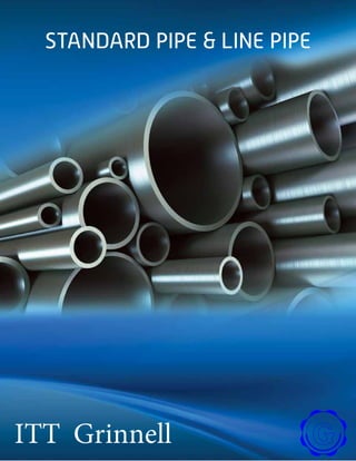
  • 1. Standard Pipe & Line Pipe I ITT Grinnell
  • 2. C O N T E N T S General Information 3 Facilities 8 Product Properties 21 Comparative Specifications 24 Pipe Tables 41 Glossary 65DAT A T disclaimer all material contained in this publication is for general information only. this material should not, therefore, be used or relied upon for any specific application without independent competent professional examination and verification of its accuracy, suitability and applicability. anyone making use of the material does so at their own risk and assumes any and all liability resulting from such use. ITT GrinnellProducts disclaims any and all expressed or implied warranties of merchantability and/or fitness for any general or particular purpose. RA 2
  • 3. General InformationlIfooT NT T T T GeneraL inFOrmatiOn ITT Grinnell employees are deeply committed to being easy to do business with anywhere in the world. As an industry-leading manufacturer, our focus is to offer the widest range of products and to exceed your expectations for on-time delivery, easy installation, performance and operating efficiency. Our Mission: To be the market leader in the development, manufacture and worldwide sale of quality air moving and control equipment with total commitment to the customer. Our commitment to our customers is what drives our long- standing sustainability practices. We continuously strive to reduce energy usage and other production costs to ensure competitive prices for you and ongoing business success. We support the health, safety and training of our employees to achieve the high quality product performance you expect from ITT Grinnell — and deserve. And we take on the industry’s most complex challenges by introducing innovative new product solutions to meet your future needs. 3
  • 4. TT AR TDA T TMAIITAIAI T IT TMTTTI AAI I Sizes and Grades ITT Grinnell Products provides seamless and electric resistance welded pipe in Od sizes ranging from ۱/۲ inches to ٤۸ inches. a variety of end finishes, lengths, grades and wall thicknesses are available. to ensure the absolute highest quality, ITT Grinnell Products has implemented a Quality management System in full compliance with aPi Q1 and TUV , .ITT Grinnell Products maintains aPi licenses to manufacture and monogram products to aPi specifications 5Ct and 5L. in addition, Fairfield tubular Operations, Lorain tubular Operations, mcKeesport tubular Operations and texas tubular Operations manu- facturing facilities are all TUV certified. a full line of aPi grades and proprietary grades are produced to meet specialized customer needs, including HiC-resistant pipe for use in H2 S environments and pipe grades with superior impact properties even under extremely cold arctic conditions. the steels of today are far more sophisticated than metals of earlier eras. the addition of alloys, plus an array of field-testing, lab-testing, melting, casting and hot-rolling practices, along with specialized heat treatments, have created steels that are precisely crafted to meet and/or exceed demanding product requirements. ITT Grinnell innovative software applications calculate, measure, test, record and analyze every aspect of the modern steelmaking process. at ITT Grinnell , we use cutting-edge technology to manage every aspect of production. real-time communication between control room and machine operators allows for precise regulation of each step of the process, from charging furnaces with raw ingredients to controlling temperatures, timing, alloying, flows, testing and transport. ITT Grinnell commitment to the tubular busi- ness is even stronger today than it was when we went into the business more than a century ago. Upgrades to our facilities and investments in new technology give us the latest tools to provide our customers with consistent high-quality products. Sizes and Grades Chart Type of Pipe Regular Mill Production Size Range, NPS Size Range, Inches Wall Thickness Range, Inches Max. Length, Feet Seamless 1.5 - 26 1.900 - 26 OD 0.140 - 2.312 48 Electric Resistance Weld 2 - 20 2.375 - 20.000 OD 0.154 - 0.625 80 General Information 4
  • 5. General Information Grades of steel vary in chemical composition from simple carbon manganese to complex multi-element micro-alloyed composition. Precise control of compositions and manufactur- ing processes allows for the manufacture of tubular products with a wide variety of properties and attributes. When selecting the proper Material Specification, Pipe Grade, ASTM Special Requirement, API 5L Product Service Level (PSL), API 5L Annex Requirement or CSA Z245.1 Category or Service Group, the end use and method of pipe fabrica- tion should be considered. Various practices are employed in all phases of steel production, which determine the type and quality of the finished product. 5
  • 6. USS M1020 Plain End ERW Pipe for Water Well Applications USS M1021 Plain End ERW Pipe for Use in Structural Applications USS M1024 Seamless Mechanical Tubing in Sizes from NPS 2 thru 26 USS M1029 Plain End Seamless Pipe for Use in General Purpose Applications USS M1400 Constructional Alloy Steel Seamless Mechanical Tubing – Grades USS “T-1” Type A and USS “T-1” Type B USS M1407 ERW Pipe NPS 8 thru 12 for Lift Devices USS M1430 Seamless Steel Slurry Pipe - Grade USS 430 USS M1431 Seamless Slurry Pipe to be Heat Treated. Primarily for Mechanical Joining USS M1470 Seamless Steel Pipe for Fabrication into Ordinary Welding Fittings USS M1471 Seamless Steel Pipe for Fabrication into High-Strength Welding Fittings USS M1475 Seamless Steel Pipe for Manufacture of Cold-Formed Fittings USS M2430 ERW Pipe Intended for Transportation of Solids in Slurry Form Pressure Determinations Barlow’s Formula is commonly used to determine the following: • Internal Pressure at Minimum Yield • Ultimate Burst Pressure • Maximum Allowable Operating Pressure, and • Mill Hydrostatic Test Pressure This formula is expressed as P = , where: P = pressure, psig t = nominal wall thickness, inches D = outside diameter, inches S = allowable stress, psi To illustrate, assume a seamless piping system 8-5/8” OD x 0.375” wall specified to API 5L Grade B which has a specified minimum yield strength (SMYS) of 35,500 psi and a specified minimum tensile strength (SMTS) of 60,200 psi. Internal Pressure at Minimum Yield S=SMYS (35,500 psi) and P= = = 3,087 or 3,090 psig (rounded to nearest 10 psig) 2St D MT ITT Grinnell material Standards ITT Grinnell material standards are specifications not covered by a society, association or other specify-ing body. the following includes the material standards used most frequently for tubular applications. 2 (35,500) (0.375) 8.625 2St D General Information 6
  • 7. Ultimate Burst Pressure at Minimum Tensile S = SMYS (60,200 psi) and P = = = 5,234.7 psig or 5,230 psig (rounded to nearest 10 psig) Maximum Allowable Operating Pressure (MAOP) S=SMYS (35,500 psi) reduced by a design factor, for example 0.72, and P = = = 2,222.6 psig or 2,220 psig (rounded to nearest 10 psig) Mill Hydrostatic Test Pressure S=SMYS (35,500 psi) reduced by a factor depending on OD and grade (0.60 for 8-5/8” OD Grade B) and P = = = 1,852.2 psig or 1,850 psig (rounded to nearest 10 psig) Some safety codes and regulatory agencies also assign a longitudinal joint factor to account for weld efficiency. The more common are 0.85 for ERW pipe and 0.60 for CW pipe. Seamless pipe enjoys a joint factor of 1.00. This means that some designers consider ERW pipe as 85 percent as efficient as seam- less pipe and CW pipe only 60 percent as efficient for the same application. Therefore, for a given application, ERW pipe would require a heavier wall than seamless pipe, and CW pipe, in turn, would require a heavier wall than ERW pipe. Distributors who stock pipe in a combination of seamless, ERW, and CW must exercise extreme care to see that pipe with joint efficiency factors of 0.85 or 0.60 is not used on jobs which require pipe with a joint factor of 1.00. Wall Thickness Barlow’s Formula is also useful in determining the wall thickness required for a piping system. To illustrate, assume a piping system has been designed with the following criteria: 1. A working pressure of 2,000 psig (P) 2. The pipe to be used is 8-5/8” OD (D) specified to API 5L Grade B (SMYS = 35,500 psi) Rearranging Barlow’s Formula to solve for wall thickness gives: t = = = 0.243 wall Wall thickness does not affect the outside diameter; only the inside diameter is affected. For example, the outside diameter of a one-inch extra-strong piece of pipe compared with a one-inch standard weight piece of pipe is identical; however, the inside diameter of the extra-strong is smaller than the inside diameter of the standard weight because the wall thickness is greater in the extra-strong pipe. 2 (60,200) (0.375) 8.625 2St D 2 (35,500 x 0.72) (0.375) 8.625 2St D 2 (35,500 x 0.60) (0.375) 8.625 2St D (2,000) (8.625) 2 (35,500) PD 2S General Information 7
  • 9. Fairfield, Alabama - 4-1/2” to 9-7/8” OD Seamless Manufacturing Process Cast Round Billets Rotary Piercing Mill (RPM) Round Reheating Mandrel Mill Shell ReheatingCooling Bed Stretch Reducing Mill Batch Saws NDT Inspection In-Process Storage Fairfield Tubular Operations can produce approximately 840,000 net tons of seamless tubular products every year. The process begins with solid steel rounds, or billets, being cut to a specified length and sent through a walking-beam reheat furnace, where temperatures reach nearly 2,300°F. The yellow rounds are turned into a tube shell in mere seconds in the rotary piercing mill as the preheated billets are cross-rolled between two barrel-shaped rolls at a high speed. The seamless shells enter Fairfield’s seven- stand mandrel mill, where they are rolled over a retained mandrel to provide the needed OD size and wall thickness for the next process. The process is carefully monitored using a state-of-the-art hot-wall measuring system. The shells are then reheated for final forming in a 24-stand stretch-reducing mill, where outside diameters are formed to customers’ exacting specifications. Wall thickness is again verified using a hot-wall measuring system. After being rotated and advanced on the walking-beam cooling bed, the pipes are batch cut and transferred to an in-process storage area, where they are handled by computer-controlled gantry cranes. Manufacturing: Seamless OD Range: 4-1/2” to 9-7/8” Walls: 0.205” to 1.200” Lengths: SRL, DRL Grades: ASTM A 106B/A53 B, API5L GRADE B, X42, X52, X60, X65, X70, ASTM A333, CSA Z245.1 Grades 241 thru 483 Cut-Off Facilities Facilities Facilities 9
  • 10. Austenitizing Furnace Sizing MillHot Straightener Quenching Unit Tempering Furnace Cooling Bed Straightening Hydrostatic Testing NDT Inspection Facing and Beveling Final Inspection From this in-process storage, pipe can be delivered to one of three primary workstations: heat treating, finishing or special pipe processing. Depending on grade, pipe might undergo quenching and tempering to alter its micro- structure to improve strength or other properties. Quenching and tempering controls hardness, reduces brittleness, and brings the steel to tensile and yield strengths required for the specified grade. Seamless pipe that has not been quenched and tempered passes initially through a straightener and then a non-destructive testing (NDT) unit. (Q&T pipe goes directly to the NDT area.) Electromagnetic inspection (EMI) detects longitudinal and transverse flaws as the pipe moves though a set of coils. Ultrasonic testing is used to verify wall thickness. Grade/composition is verified on each pipe by eddy current. All pipe is hydro-tested. Finished pipe is weighed, measured, stenciled with a unique identification, coated and loaded onto rail cars for shipment to customers. Facilities Cut-Off Facilities Heat Treating Finishing 10
  • 11. McKeesport, Pennsylvania - 8-5/8” to 20” OD Electric Resistance Weld Manufacturing Process Coil Feed Ramp Fin Pass SectionFirst Forming Section High Frequency Welder Sizing Mill Seam NormalizerAir Cooling & Water Cooling Weld Seam Ultrasonic Inspection Flying Cut-Off McKeesport Tubular Operations sits on the original site of National Tube Works. McKeesport has been making tubular products since the 1870s and electric-resistance weld pipe since 1964. Steel arrives at the facility in coils that are unrolled, cut and welded into a continuous strip before entering the mill. The strip steel passes through a series of forming rolls, which transform the strip from flat steel to a round pipe section. The fin pass section of the mill finishes the rounding process and contours the edges of the strip for seam welding. The high-frequency welder heats the edges of the rolled strip to approximately 2,600°F. Pressure rolls then squeeze the heated edges together to form a fusion weld. The weld is inspected by an ultrasonic non-destructive inspection unit. The pipe then enters the seam normalizer where the weld area is heat treated as per API specification to remove welding stresses and produce a uniform normalized grain structure. The weld is cooled in air below transformation temperature and then water-cooled to near ambient before passing through the sizing mill, where idler side-closing rolls straighten the pipe and size it to the correct outside diameter. As the continuous length of pipe moves down the mill, the flying cut-off cuts lengths of pipe Manufacturing: Electric Resistance Weld OD Range: 8-5/8” to 20” Walls: 0.188” to 0.406” Lengths: SRL 18’-22’; DRL 39’-45’; TRL 33’-65’; QRL 42’-80’ max Grades: ASTM A53 B, API5L GRADE B, X42, X52, X60, X65, X70, ASTM A523 A (cable pipe), CSA Z245.1 Grades 241 thru 483 Facilities 11
  • 12. Facilities Final Inspection Cut-Off Facilities Hydrostatic Testing Straightening Finishing Non-Destructive Inspection without interrupting the production line. Each pipe is hydrostatic tested to ensure rated strength and weld integrity under pressure. After hydrotesting, any bow in the pipe is removed by passage through a multi-stand straightener. The pipe enters the finishing floor where the weld is ultrasonically inspected and the pipe is examined by automated electromagnetic inspection. After being cut to customer-specified lengths, the pipe is finished and prepared for shipment. Facing and Beveling 12
  • 13. Lone Star, Texas - Mill No. 1 - 8-5/8” to 16” OD Electric Resistance Weld Manufacturing Process Full-Body Normalize Hot Reduce Cool TTMNER T TT T ITT Grinnell Operations mill no. 1 manufactures high-quality erW tubular products primarily for the oil and gas industries. Steel arrives at the facility in coils slit to precise width before the manufacturing process begins. the strip steel is uncoiled, leveled, conveyed through a side trimmer, which shears both edges to provide proper width and clean surfaces for welding. the strip then passes through a series of forming rolls, which transform the coil from a flat strip of steel to round pipe sections. the edges of the strip are contoured for seam welding. the weld is created by heat obtained from the pipe’s resistance to the flow of electric current of the circuit of which it is part, and by applied pressure to form a forged weld. No filler metal is used in the welding process. After the flash (metal extruded by the weld process) is removed from the pipe’s inside and outside surfaces, the pipe is cut to length by a flying rotary cutoff. Weld integrity is checked by ultrasonic test equipment in line behind each welder. The pipe passes through a series of induction heating furnaces where the entire pipe is heated to temperatures above 1,650°F and allowed to air cool. This full-body normalizing operation Manufacturing: Electric Resistance Weld OD Range: 8-5/8” to 16” Walls: 0.250” to 0.562” Lengths: SRL, DRL, TRL Grades: ASTM A53 B, API5L GRADE B, X42, X52; Q&T Grades: X60, X65, X70, X80 Uncoil & LevelFlash Trim UST & Cut ER Weld Cage Mill Form Edge Trim Coil Facilities 13
  • 14. Straighten Hydrostatic TestBevel Final Inspection Weld USTPipeimage® Full Body UST Weigh, Measure, Stencil & Ship Upon Agreement Only Facilities produces uniform grain structure throughout the entire pipe wall. The normalizing furnaces may also heat the pipes for diameter reduction and a more uniform finished product. After cooling, pipe is sized, straightened, visually inspected, stenciled with the appropriate identity and queued for finishing. Laboratory tests confirm full compliance to specifications and other mechanical property requirements before the pipe is beveled, electromagnetically inspected and hydrostatically tested. Multiple certifications are available. NDT Inspection Cut-Off Facilities Facing and Beveling 14
  • 15. Lone Star, Texas - Mill No. 2 - 2-3/8” to 6-5/8” OD Electric Resistance Weld Manufacturing Process Uncoil & LevelFlash Trim UST & Cut ER Weld Form Edge Trim Full-Body Normalize Hot Stretch Reduction Cool Coil TTMNER T TTTN ITT Grinnell Operations mill no. 2 manufactures high-quality erW tubular products primarily for the oil and gas industries. Steel arrives in coils slit to precise width. the strip steel is uncoiled, leveled, conveyed through a side trimmer, which shears both edges to pro- vide proper width and clean surfaces for welding. the strip then passes through a series of forming rolls, which transform the coil from a flat strip of steel to round pipe sections. the edges of the strip are contoured for seam welding. the weld is created by heat obtained from the pipe’s resistance to the flow of electric current of the circuit of which it is part, and by applied pressure to form a forged weld. no filler metal is used in the welding process. After the flash (metal extruded by the weld process) is removed from the pipe’s inside and outside surfaces, the pipe is cut to length by a flying rotary cutoff. Weld integrity is checked by in-line ultrasonic test equipment. The pipe then passes through a series of induction heating furnaces where the entire pipe is heated to temperatures above 1,650°F and allowed to air cool. This full-body normalizing operation produces uniform grain structure throughout the entire pipe wall. The normalizing furnaces also heat the pipes for diameter reduction and a more uniform finished product. Grades X60 through X80 require heat treatment and quenching. (This additional process is not shown in the flow diagram.) Manufacturing: Electric Resistance Weld OD Range: 2-3/8” to 6-5/8” Walls: 0.154” to 0.531” Lengths: SRL, DRL Grades: ASTM A53 B, API5L GRADE B, X42, X52; Q&T Grades: X60, X65, X70, X80 Cut-Off Facilities Facilities 15
  • 16. Straighten Hydrostatic TestBevel Eddy CurrentWeigh, Measure, Stencil & Ship Final Inspection Finishing 2-3/8” - 4” Finishing 4” - 6-5/8” Straighten Hydrostatic Test Eddy Current Final Inspection Weld USTPipeimage® Full Body UST Weigh, Measure, Stencil & Ship Bevel Upon Agreement Only Facilities After cooling, pipe is straightened, visually inspected, stenciled with the appropriate identity and queued for finishing. In the finishing department, the pipe is beveled, eddy current inspected and hydrostatically tested. Full-body electromagnetic and ultrasonic testing is avail- able for pipe sizes 4” and larger. Laboratory Cut-Off & Re-Bevel (As Needed) Cut-Off & Re-Bevel (As Needed) tests confirm full compliance to specifications and other mechanical property requirements. Multiple certifications are available. 16
  • 17. Rotary Billet Heating Reheat FurnacePlug Rolling Mill Rotary Piercing Mill (RPM) Second Piercing (Elongator) Lorain, Ohio - Mill No. 3 - 10-3/4” to 26” OD Seamless Manufacturing Process Cast Round Billets Rotary Expanding Mill Reheating Furnace Sizing MillReeling Mill Lorain Mill No. 3 manufactures superior seamless pipe, beginning with the processing of continuous cast round billets using the latest steelmaking technology. The cast round billets begin their journey in the rotary hearth furnace where temperatures exceed 2,300°F. The preheated round billets are processed through a piercing mill to form a pierced billet or shell. The hot shell is then run through a second piercing mill and a plug rolling mill to increase diameter and length, and to reduce and improve the uniformity of the wall thickness. As the billet goes through the first piercer, it is gripped by rolls, which rotate and advance it over the piercer point, forming a hole through its length. The second piercing mill further increases the diameter and length of the shell and reduces the wall thickness. The pierced hot shell passes through the plug rolling mill to again reduce the wall thickness and to increase the length. Pipe larger than 16” OD is reheated and sent through a rotary rolling mill, which uses large discs to expand the hot pipes up to 26” in diameter. Rotary rolling can produce pipe as long as 48 feet. The pipe then passes through the reeling and sizing mills. The reeling mill grips the pipe and advances it over a mandrel, burnishing the inside and outside surfaces. After moving through an intermediate cooling station, the pipe proceeds on one of two paths. Manufacturing: Seamless OD Range: 10-3/4” to 26” Walls: 0.365” to 2.312” Lengths: SRL, DRL Grades: ASTM A 106B/A53 B, API5L GRADE B, X42, X52, X60, X65, X70, ASTM A333, CSA Z245.1 Grades 241 thru 483 Reheat Furnace Direct Roll 10.75”-16” Rotary Roll 16”-26” Facilities 17
  • 18. Facilities Cooling Bed Rotary Straightener Hydrostatic Testing NDT InspectionFacing & Beveling Finishing Final Inspection If the steel is an as-rolled carbon grade prod- uct, it is heat-equalized in a walking-beam reheat furnace and then sent through a three-stand sizing mill to reach final outside dimension. If the steel requires heat treating, the reheat furnace’s temperature is raised to austenitize the pipe. The steel exits the furnace and passes through a state-of-the-art OD/OD-ID quench and walking-beam temper furnace (not pictured) before rejoining the main production line to pass through the three-stand sizing mill. After sizing, the pipe is allowed to cool on slowly moving conveyor tables in preparation for straightening. For products that require hot straightening, these cooling tables are bypassed and the pipe is sent directly from the sizer to the straightener. The pipe is then ready for finishing. The pipe undergoes NDT inspection to detect any body wall imperfections. Any imperfections are proved up and dispositioned in accordance with specified tolerances. After inspection, an expanding arbor holds the pipe in line while a revolving head faces and bevels the end of the pipe. The finished pipe is visually inspected and subjected to a hydrostatic test as a strength and leak check before shipping. When required by specification or customer order requirements, the pipe is processed through one of several offline UT and special end area inspection units. Cut-Off Facilities 18
  • 19. Lorain, Ohio - Mill No. 4 - 1.900” to 4-1/2” OD Seamless Manufacturing Process Rotary Hearth Furnace Mandrel MillPiercing Mill Reheat Furnace Run-Out/ Finishing Cooling BedBatch Sawing Stretch Reducing Mill (SRM) The process at Lorain Mill No. 4 begins with continuous cast 6” round billets being heated in a rotary hearth furnace to proper temperature for piercing. The heated billets are center punched and pierced by advancing the billet over a piercer point in the piercing mill. The pierced billet or shell is transferred to a mandrel mill and rolled over a solid mandrel where the OD is reduced and the length is increased. The shell is then reheated to proper rolling tempera- ture in preparation for the final rolling process. The hot shell is run through a descaling unit to prepare the OD surface for rolling and run through the stretch reducing mill. At this stage, the final OD and wall thickness are established for the pipe. A AT T NTTND after exiting the stretch reducing mill, the pipe is allowed to cool on a walking-beam cooling bed. Sample inspections are also conducted at this point. after cooling, the pipe is batched, stenciled and sawed to the specified length. the sawed pipe is then transferred to a run-out table and moved to finishing. Pipe ends are faced on dual automatic facers, pipe is hydrotested and sample inspections are done. Upsetting, heat treating, additional inspec- tion and hydrotesting are done to meet customer specifications at ITT Grinnell Houston tubular Processing Services operation or at the Lorain no. 6 Q&t and Finishing Complex. the new no. 6 facility can heat treat and finish pipe Ods from 2.375” thru 7.625”. Manufacturing: Seamless OD Range: 1.900” to 4-1/2” Walls: 0.140” to 0.674” Lengths: SRL and DRL Grades: ASTM A 106B/A53 B, API5L GRADE B, X42, X52, X60, X65, X70, ASTM A333, CSA Z245.1 Grades 241 thru 483 Facilities 19
  • 20. Lorain, Ohio - Mill No. 6 - 2-3/8” to 7-5/8” OD Quench and Temper and Finishing Process Austenitizing Furnace Tempering FurnaceQuenching Unit Straightening Cut-Off Facilities NDT Inspection & Sea Weld Seam UT Inspection for ERW pipe Hydrostatic Testing Facing & Beveling Grade Comparer Weigh, Measure, Stencil, Coat & Ship Manufacturing: Seamless & Electric Resistance Weld OD Range: 2-3/8” to 7-5/8” Walls: 0.205” to 0.812” Lengths: 20’ to 48’ Grades: ASTM A 106B/C, A53 B, A333 Grades 1 and 6, API5L B, X42, X52, X60, X65, X70, ASTM A333, CSA Z245.1 Grades 241 thru 483 Final Inspection The No. 6 Quench and Temper and Finishing Facility was built in 2011. The facility processes pipe from 2.375 to 7.625 inches in outside diameter, with a wall thickness of up to 0.812 inches, and to a maximum finished pipe length of 48 feet. Green tubes to be heat treated arrive in railroad cars and are loaded on to a charge table with the use of a magnet crane. Pipe is conveyed into the austenitizing furnace, heated to the required temperature and then cooled with an OD water quench to below 200°F. After entering the tempering furnace, precise control of the temperature is used to control the mechanical properties along the length of the pipe. Pipe travels through a 100-ton, 6-roll opposing straightener and then on to a walking- beam cooling bed. The finishing portion of the facility starts with a combination EMI/UT unit and an SEA inspection unit where longitudinal and transverse flaws can be detected and wall thickness can be verified. Each pipe is then hydrostatically tested to ensure rated strength under pressure. ERW pipe undergoes an additional test when the weld seam is inspected with an in-line UT inspection unit. After testing is complete, the pipe is sent through the finishing process. Before shipment to the customer, pipe is grade-verified, length measured, weighed, stenciled and coated. Facilities 20
  • 22. Product Properties Product PropertiesT AAD T T AIATM ITT Grinnell Products manufactures both seamless and welded pipe to meet specific customer requirements. advanced manufacturing techniques and controls ensure high quality, uniform, economical products. a complete range of Ods, end finishes and lengths are available. Seamless Standard Pipe and Line Pipe ITT Grinnell Products manufactures its seamless pipe by piercing solid billets of fully killed steel. this “seamless” method of manufac- ture is a forging operation that only the soundest, toughest steel can tolerate. Chemical and mechanical property require- ments are as prescribed by current aPi, aStm, AMEATD T aSme and applicable CSa standards. ITT Grinnell Products is the only domestic producer of seamless pipe in the 11-3/4” to 26” Od size range. ITT Grinnell Products provides seamless Standard Pipe and Line Pipe for a wide range of applications. Our seamless pipe has an unsurpassed record of safety, and uniform strength and ductility, making it the product of choice for critical applications. Standard Pipe is widely used primarily in the construction, refining, chemical and petro- chemical industries. Line Pipe is used for the transmission of crude oil, natural gas and petro- leum products as well as for water and slurry pipeline applications. Availability – Standard Diameters and Walls Size1 Wall Thickness,2 Inches NPS OD (Inches) Lorain, OH Fairfield, AL 1 1/2 1.900 0.140-0.281 - 2 2 3/8 0.154-0.436 - 2 1/2 2 7/8 0.160-0.552 - 3 3 1/2 0.170-0.600 - 3 1/2 4 0.180-0.650 - 4 4 1/2 0.188-0.674 0.205-0.750 5 5 9/16 - 0.250-0.750 6 6 5/8 - 0.250-0.870 8 8 5/8 - 0.250-1.200 10 10 3/4 0.307-2.000 - 12 12 3/4 0.330-2.312 - 14 14 0.375-2.000 - 16 16 0.375-2.000 - 18 18 0.375-1.562 - 20 20 0.375-1.512 - 22 22 0.375-1.375 - 24 24 0.375-1.250 - 26 26 0.375-1.125 - 1 Sizes between NPS 1 1/2 and 26 not listed subject to inquiry. 2 Maximum wall varies for grades over X42 and is subject to mill inquiry. 22
  • 23. electric resistance Weld (erW) Standard Pipe and Line Pipe ITT Grinnell Products’ erW Standard Pipe and Line Pipe are smoothly finished, thin-walled, extra-long products produced by continuously forming coiled bands and welding the longitudinal seam using high-frequency electric resistance welding. Chemical and mechanical property requirements are as prescribed by current aPi 5L and applicable aStm standards. erW Standard Pipe and Line Pipe are widely used throughout the oil and gas industry, as well as for pipe piling, pipe-type cable systems and hydraulic hoists. Characteristics and Advantages Eighty-Foot Lengths – Ultra-long lengths of ITT Grinnell Products erW pipe, available from mcKeesport tubular Operations minimize TT T A handling time in transportation and installation, and significantly reduce field welding labor, time and costs. Smooth Surfaces – ITT Grinnell Products hot rolled strip steel is continuously cold formed into smooth-surfaced, uniform-gage pipe for superior flow characteristics. Stronger, Lighter Walls – the improved, higher strength, lighter gage steel bands used by ITT Grinnell Products are fused by high- frequency electric resistance welders into rugged pipe that can meet exacting tolerances and strength specifications. Uniform Dimensions and Quality – Higher auto- mated production, combined with continuous non-destructive and visual inspection and hydrostatic testing, assures a pipe product of excellent quality. and, because the pipe is made from flat-rolled steel, it has highly uniform wall thicknesses. McKeesport, PA Availability (Subject to inquiry) Size1 Wall Thickness,2 Inches NPS OD 8 8 5/8 0.172-0.406 10 10 3/4 0.172-0.400 12 12 3/4 0.188-0.406 14 14 0.188-0.406 16 16 0.203-0.406 18 18 0.219-0.406 20 20 0.250-0.413 1 Sizes not listed subject to inquiry. 2 Maximum wall varies for grades over X42 and is subject to mill inquiry. Lone Star, TX Availability (Subject to inquiry) Size1 Wall Thickness,2 Inches NPS OD 2 2 3/8 0.218-0.344 2 1/2 2 7/8 0.203-0.375 3 3 /1/2 0.216-0.300 3 1/2 4 0.226-0.318 4 4 1/2 0.237-0.531 5 5 9/16 0.258-0.500 6 6 5/8 0.280-0.432 8 8 5/8 0.250-0.438 10 10 3/4 0.279-0.500 12 12 3/4 0.250-0.500 14 14 0.312-0.562 16 16 0.375-0.562 1 Sizes not listed subject to inquiry. 2 Maximum wall varies for grades over X42 and is subject to mill inquiry. Product Properties 23
  • 24. Comparative Specifications The following information is summarized from ASTM standards and API Specification 5L in effect at the time of publication. Please refer to the specific standards or specifications for more details. A53 Seamless and Welded Standard Pipe Specification A53 covers seamless and welded, black and hot-dipped galvanized nominal (average) wall pipe for coiling, bending, flanging and other special purposes and is suitable for welding. Mechanical Properties – Tensile Requirements Seamless and ERW Grade A Grade B Tensile Strength, min., psi 48,000 60,000 Yield Strength, min., psi 30,000 35,000 Chemical Requirements Seamless and ERW C max % Mn max % P max % S max % Grade A 0.25 0.95 0.05 0.045 Grade B 0.30 1.20 0.05 0.045 Testing Requirements Hydrostatic Testing Hydrostatic inspection test pressures for plain end and threaded and coupled pipe are specified. Hydrostatic pressure shall be maintained for not less than 5 seconds for all sizes of Seamless and ERW pipe. Mechanical Tests Tensile Test – Two transverse tests required on ERW for NPS 8 and larger, one across the weld and one opposite the weld Flattening Test – On ERW for NPS 2 and larger, STD and XS walls (not required for XXS pipe) Bending Test (Cold) – for NPS 2 and under, XS wall and under; for NPS 1-1/4 and under, XXS wall Degree of Bend Diameter of Mandrel For Normal A53 Uses 90 12 x nom. dia of pipe For Close Coiling 180 8 x nom. dia of pipe Number of Tests Seamless and Electric Resistance Weld – bending, flattening, tensile on one length of pipe from each lot of 500 lengths, or less, of each pipe size. Comparative Specifications 24
  • 25. A53 Seamless and Welded Standard Pipe Permissible Variations Wall Thickness The minimum wall thickness at any point shall not be more than 12.5% under the nominal wall thickness specified. Weights Per Foot Plus or minus 10% Outside Diameter Outside diameter at any point shall not vary from standard specified more than: NPS Over Under 1 1/2 and smaller +1/64” -1/64” 2 and larger +1% -1% Lengths Standard Wall Single Random – 16’-22’; (5% may be jointers); if plain ends, 5% may be 12’-16’ Double Random – Shortest length 22’; minimum average for order 35’ Extra Strong (XS) and Double Extra Strong (XXS) Walls Single Random – 12’-22’; (5% may be 6’-12’) Double Random (XS and lighter) – Shortest length 22’; minimum average for order 35’ Lengths longer than single random with wall thicknesses heavier than XS subject to negotiation Marking Requirements on Each Length Rolled, Stamped or Stenciled (manufacturer’s option) • Name or brand of manufacturer • Specification number ASTM A53 • Size (NPS and weight class, schedule number, or specified wall thickness on specified outside diameter and specified wall thickness) • Grade A or Grade B • Manufacturing process that is ERW (E) or Seamless (S) • Test pressure (seamless only) • Non-destructive electric test (seamless only) • Length of pipe Comparative Specifications 25
  • 26. A106 Seamless Carbon Steel Pipe Specification A106 covers seamless carbon steel nominal wall pipe for high-temperature service, suitable for bending, flanging and similar forming operations. NPS 1-1/2 and under may be either hot finished or cold drawn. NPS 2 and larger shall be hot finished unless otherwise specified. Surface finish standards are outlined in the specification. Purchaser may specify NDE in lieu of hydrostatic test or neither. Unless otherwise specified, pipe is furnished with plain ends. Mechanical Properties – Tensile Requirements Seamless Grade A Grade B Grade C Tensile Strength, min., psi 58,000 70,000 70,000 Yield Strength, min., psi 36,000 50,000 40,000 Chemical Requirements Seamless Grade A Grade B Grade C Carbon max. % 0.25 0.30 0.35 Manganese % 0.27 – 0.93 0.29 – 1.06 0.29 – 1.06 Phosphorus, max. % 0.035 0.035 0.035 Sulfur, max. % 0.035 0.035 0.035 Silicon, min. % 0.10 0.10 0.10 Testing Requirements Hydrostatic Testing Inspection test pressures produce a stress in the pipe wall equal to 60% of specified minimum yield strength (SMYS) at room temperature. Maximum pressures are not to exceed 2,500 psi for NPS 3 and under, and 2,800 psi for the larger sizes. Pressure is maintained for not less than 5 seconds. Mechanical Tests Tensile Test – NPS 8 and larger – either transverse or longitudinal acceptable Smaller than NPS 8 – longitudinal only Flattening Test – NPS 2 and larger Bending Test (Cold) – NPS 2 and under Degree of Bend Diameter of Mandrel For Normal A106 Uses 90 12 x nom. dia. of pipe For Close Coiling 180 8 x nom. dia. of pipe Number of Tests NPS On One Length From Each Lot of Tensile 5 and smaller 6 and larger 400 or less 200 or less Bending 2 and smaller 400 or less Flattening 2 through 5 6 and over 400 or less 200 or less Comparative Specifications 26
  • 27. A106 Seamless Carbon Steel Pipe Permissible Variations Wall Thickness The minimum wall thickness at any point shall not be more than 12.5% under the nominal wall thickness specified. Weights per Foot Weight of any individual length shall not vary more than 10% over and 3.5% under that specified. NOTE: NPS 4 and smaller – weighed in lots. Larger sizes – weighed by individual length. Outside Diameter Outside Diameter shall not vary from standard specified below at any point. NPS Over Under 1 1/2 and smaller +1/64” -1/64” 2-4 +1/32” -1/32” 5-8 +1/16” -1/32” 10-18 +3/32” -1/32” 20-26 +1/8” -1/32” Length Requirements Lengths required shall be specified on order. No “jointers” permitted unless otherwise specified. If no definite lengths required, following practice applies: Single Random – 16’-22’ (5% may be 12’-16’) Double Random – Minimum length is 22’; minimum average is 35’ (5% may be 16’-22’) Marking Requirements On Each Length Rolled, Stamped or Stenciled (manufacturer’s option) • Manufacturer’s name or brand • A106 A, A106 B or A106 C • Hydrostatic test pressure and/or NDE, or NH if neither is specified • Length of pipe • ANSI schedule number or weight class or wall thickness • Weight per foot (NPS 4 and larger) • Additional “S” if tested to supplementary requirements Comparative Specifications 27
  • 28. A252 Piling Pipe Specification A252 covers nominal (average) wall steel pipe piles of cylindrical shape and applies to pipe piles in which the steel cylinder acts as a permanent load-carrying member or as a shell to form case-in-place concrete piles. Surface imperfections exceeding 25% of the nominal wall in depth are considered defects. Defects not exceeding 33.5% of the nominal wall in depth may be repaired by welding. Before welding, the defect shall be completely removed. Mechanical Properties – Tensile Requirements Grade 1 Grade 2 Grade 3 Tensile Strength, min., psi 50,000 60,000 66,000 Yield Strength, min., psi 30,000 35,000 45,000 Chemical Requirements Phosphorus Seamless and Welded Max % 0.050 Testing Requirements Hydrostatic Testing None specified Mechanical Tests Tensile Test – either longitudinal or transverse at option of manufacturer Number of Tests One tensile property test per 200 lengths Permissible Variations Wall Thickness Not more than 12.5% under the nominal wall thickness specified Weights per Foot The weight of any individual length of pipe shall not vary more than 15% over or 5% under the weight specified. Each individual length shall be weighed separately. Outside Diameter Shall not vary more than plus or minus 1% from the diameter specified Lengths May be ordered in single or double random lengths or in uniform lengths. Single Random – 16’ - 25’ inclusive Double Random – Over 25’ with a minimum average of 35’ Uniform – Plus or minus 1” on length specified Marking Requirements On Each Length Rolled, Die Stamped or Paint Stenciled (manufacturer’s option) Manufacturer’s name, brand or trademark, heat number, method of pipe manufacture, size, weight, length, wall thickness and ASTM A252 and the Grade. Comparative Specifications 28
  • 29. A501 Hot Formed Carbon Steel Structural Tubing Specification A501 covers hot-formed, welded and seamless carbon steel square, round, rectangular, or special shape structural tubing for welded, riveted or bolted construction of bridges and buildings, and for general structural purposes. The size range for round is NPS 1/2”-24”. Mechanical Properties – Tensile Requirements Grade A Grade B Tensile Strength, min., psi 58,000 70,000 Yield Strength, min., psi 36,000 50,000 Elongation in 2 inch min. 23% 23% Chemical Requirements Grade A Grade B Element Heat Analysis Product Analysis Heat Analysis Product Analysis Carbon, max % 0.26 .30 0.22 (A) 0.26 (A) Manganese, max % No requirement No requirement 1.40 (A) 1.45 Phosphorus, max % 0.035 0.045 0.030 0.040 Sulfur, max % 0.035 0.045 0.020 0.030 Copper (when specified), min % 0.20 0.20 0.20 0.18 A – For each reduction of 0.01 percentage point below the specified maximum for carbon, an increase of 0.06 percentage point above the specified maximum for manganese is permitted, up to a maximum of 1.50% by heat analysis and 1.60% by product analysis. Testing Requirements Hydrostatic Testing None specified Mechanical Tests Tensile Test Bend Test – on square or rectangular tubing Number of Tests One tension test and one bend test from each lot Permissible Variations Wall Thickness Not specified Weights per foot Shall not be less than the specified value by more than 3.5% Outside Diameter Round tubing NPS Over Under 1-1/2 and smaller +1/64” -1/32” 2 and larger +1% -1% Comparative Specifications 29
  • 30. A501 Hot Formed Carbon Steel Structural Tubing Lengths Produced in random lengths 16’-22’ or 32’-44’, in multiple lengths and in specific cut lengths Cut Length Tolerances Over Under 22 feet and smaller +1/2” -1/4” Over 22 feet +3/4” -1/4” Marking Requirements On Each Length Rolled, Die Stamped, Ink Printed or Paint Stenciled (manufacturer’s option) • Manufacturer’s name, brand or trademark • Size and thickness • ASTM A501 Hot-Dipped Galvanizing When required, weight of zinc shall comply with the requirements in the latest revision of Spec A53, with the additional provision that the manufacturer may determine the coating weight on outside surface only. Comparative Specifications 30
  • 31. A523 Cable Circuit Piping Specification A523 covers Seamless and Electric Resistance Welded steel pipe used as conduit for the installation of high-pressure pipe-type electrical cables. Suitable for welding and for forming operations involving flaring, belling and bending. Size Range: NPS 4-12 Mechanical Properties – Tensile Requirements Seamless and ERW Grade A Grade B Tensile Strength, min., psi 48,000 60,000 Yield Strength, min., psi 30,000 35,000 Chemical Requirements C max % Mn max % P max % S max % Heat Product Heat Product Heat Product Heat Product Grade A SMLS 0.22 0.25 0.90 0.95 0.035 0.045 0.050 0.060 Grade A ERW 0.21 0.25 0.90 0.95 0.035 0.045 0.050 0.060 Grade B SMLS 0.27 0.30 1.15 1.20 0.035 0.045 0.050 0.060 Grade B ERW 0.26 0.30 1.15 1.20 0.035 0.045 0.050 0.060 Testing Requirements Hydrostatic Testing Hydrostatic inspection test pressures are specified. Hydrostatic pressure to be maintained for not less than 5 seconds. Mechanical Tests Tensile Test – longitudinal Weld Tensile – transverse Flattening Test – seamless and ERW Number of Tests Tensile – one length from each lot of 500 or less Flattening Seamless – one length from each lot of 500 or less ERW - Single lengths – crop ends from each length Multiple lengths – crop ends from each length plus 2 intermediate rings Comparative Specifications 31
  • 32. A523 Cable Circuit Piping Permissible Variations Wall Thickness Minimum wall thickness, at any point, shall not be more than 12.5% under or more than 15.0% over the nominal wall thickness specified. Weights per Foot XS and lighter wall thickness: +5% Heavier than XS wall thickness: +10% Outside Diameter Outside Diameter shall not vary more than +1% from specified Outside Diameter End Tolerances (distance of 4” from each end) NPS Over Under 10 and smaller +1/15” -1/64” 12 +3/32” -1/32” Lengths Minimum permissible length – 35 ft. 0 in. Maximum permissible length – 50 ft. 0 in. Marking Requirements on Each Length Roll, Stamp or Paint Stencil (manufacturer’s option) Manufacturer’s name or brand, kind of pipe, i.e., Seamless (S) or ERW (E); grade, size, weight per foot or wall thickness and ASTM A523. Coatings Unless otherwise specified, the pipe shall not be given a mill coating of paint, oil or any other material inside or out. Comparative Specifications 32
  • 33. A618 Hot-Formed High-Strength Low-Alloy Structural Tubing Specifications A618 covers grades of hot-formed welded and seamless high-strength low-alloy square, rectangular, round or special shape structural tubing for welded, riveted or bolted construction of bridges and buildings and general structural purposes. Mechanical Properties – Tensile Requirements Seamless and ERW Grade la & lb Grade II Grade III Tensile Strength, min., psi 70,000 60,000 65,000 Yield Strength, min., psi 50,000 50,000 50,000 Chemical Requirements Grade la Grade lb Grade II Grade III Heat Product Heat Product Heat Product Heat Product Carbon, max. % 0.15 0.18 0.20 - 0.22 0.26 0.23 0.27 Manganese % 1.00 max. 1.04 max. 1.35 max. 1.40 max. 0.85-1.25 1.30 max. 1.35 max. 1.40 max. Phosphorus, max % 0.15 0.16 0.025 0.035 0.025 0.035 0.025 0.035 Sulfur, max. % 0.025 0.045 0.025 0.035 0.025 0.035 0.025 0.035 Silicon, max % - - - - 0.30 0.33 0.30 0.35 Copper, min. % 0.20 0.18 0.20 0.18 0.20 0.18 - - Vanadium, min. % - - - - 0.02 0.01 0.02 0.01 • Grade la equivalent to USS COR-TEN A • Grade lb equivalent to USS COR-TEN B • Grade II equivalent to USS TRI-TEN • Grade III equivalent to USS EX-TEN 50 Testing Requirements Hydrostatic Testing Not specified Mechanical Tests Tensile (longitudinal) test Bend test Number of Tests Two of each per heat Comparative Specifications 33
  • 34. A618 Hot-Formed High-Strength Low-Alloy Structural Tubing Permissible Variations Wall Thickness Not specified Weights per Foot Not less than the specified weight by more than 3.5% Outside Diameter Round tubing NPS Over Under 1-1/2 and smaller +1/64” -1/32” 2 and larger +1% -1% Lengths Produced in random lengths 16’-22’ or 32’-44’, in multiple lengths and in specific cut lengths Cut Length Tolerances Over Under 22 feet and smaller +1/2” -1/4” Over 22 to 44 feet +3/4” -1/4” Marking Requirements on Each Length Rolled, Die Stamped, Ink Printed or Stenciled (manufacturer’s option) • Manufacturer’s name, brand or trademark • Size and wall • Steel grade • ASTM A618 Comparative Specifications 34
  • 35. API 5L Line Pipe Specification API 5L covers seamless and welded pipe suitable for use in conveying gas, water, oil and other liquefied media. Chemical Requirements Specification Grade Cb Mnb P S Si Cr Mo Ni V Cb Ti API 5L 44th Ed (PSL 1) Seamless A25 .21 .60 .030 .030 - - - - - - - A .22 .90 .030 .030 - - - - - - - B .28 1.20 .030 .030 - - - - c,d c,d d X42 .28 1.30 .030 .030 - - - - d d d X46 .28 1.40 .030 .030 - - - - d d d X52 .28 1.40 .030 .030 - - - - d d d X56 .28 1.40 .030 .030 - - - - d d d X60 .28e 1.40e .030 .030 - - - - f f f X65 .28e 1.40e .030 .030 - - - - f f f X70 .28e 1.40e .030 .030 - - - - f f f API 5L 44th Ed (PSL 1) Welded A25 .21 .60 .030 .030 - - - - - - - A .22 .90 .030 .030 - - - - - - - B .26 1.20 .030 .030 - - - - c,d c,d d X42 .26 1.30 .030 .030 - - - - d d d X46 .26 1.40 .030 .030 - - - - d d d X52 .26 1.40 .030 .030 - - - - d d d X56 .26 1.40 .030 .030 - - - - d d d X60 .26e 1.40e .030 .030 - - - - f f f X65 .26e 1.40e .030 .030 - - - - f f f X70 .26e 1.65e .030 .030 - - - - f f f a. .50% max Cu, Ni, Cr and .15 max Mo. For grades up to and including X52, Cu, Cr and Ni shall not be added intentionally. b. For each reduction of .01% below the max C, and increase of .05% Mn is permitted up to a max of 1.65% for grades B, X42 and X52, up to 1.75% for grades >X52 and < X70, and 2.0% for X70. c. Unless otherwise agreed Cb + V < = .15%. d. Cb + V + Ti < = .15%. e. Unless otherwise agreed. f. Unless otherwise agreed the sum of Cb + V + Ti < = .15%. Specification Grade Cond Cb Mnb P S Si V Cb Ti Other IIW Pcm API 5L 44th Ed (PSL 2) (Seamless & Welded) B R or N .24 1.20 .025 .015 .40 c c .04 e .43 .25 X42 R or N .24 1.20 .025 .015 .40 .06 .05 .04 e .43 .25 X46 N .24 1.40 .025 .015 .40 .07 .05 .04 d, e .43 .25 X52 N .24 1.40 .025 .015 .45 .10 .05 .04 d, e .43 .25 X56 N .24 1.40 .025 .015 .45 .10f .05 .04 d, e .43 .25 X60 N .24f 1.40f .025 .015 .45f .10f .05f .04f d, h as agreed to API 5L 44th Ed (PSL 2) (Seamless & Welded) B Q .18 1.40 .025 .015 .45 .05 .04 .04 e .43 .25 X42 Q .18 1.40 .025 .015 .45 .06 .05 .04 e .43 .25 X46 Q .18 1.40 .025 .015 .45 .07 .05 .04 e .43 .25 X52 Q .18 1.50 .025 .015 .45 .10 .05 .04 e .43 .25 X56 Q .18 1.50 .025 .015 .45 .10 .05 .04 d, e .43 .25 X60 Q .18f 1.70f .025 .015 .45f (V + Cb + Ti < = .15) e .4 .25 X65 Q .18f 1.70f .025 .015 .45f (V + Cb + Ti < = .15) h .43 .25 X70 Q .18f 1.80f .025 .015 .45f (V + Cb + Ti < = .15) h .43 .25 X80 Q .18f 1.90f .025 .015 .45f (V + Cb + Ti < = .15) i, j as agreed to Comparative Specifications 35
  • 36. Specification Grade Cond Cb Mnb P S Si V Cb Ti Other IIW Pcm API 5L 44th Ed (PSL 2) (Welded Only) B M .22 1.20 .025 .015 .45 .05 .05 .04 e .43 .25 X42 M .22 1.30 .025 .015 .45 .05 .05 .04 e .43 .25 X46 M .22 1.30 .025 .015 .45 .05 .05 .04 e .43 .25 X52 M .22 1.40 .025 .015 .45 (V + Cb + Ti < = .15) e .43 .25 X56 M .22 1.40 .025 .015 .45 (V + Cb + Ti < = .15) e .43 .25 X60 M .12f 1.60f .025 .015 .45f (V + Cb + Ti < = .15) h .43 .25 X65 M .12f 1.60f .025 .015 .45f (V + Cb + Ti < = .15) h .43 .25 X70 M .12f 1.70f .025 .015 .45f (V + Cb + Ti < = .15) h .43 .25 X80 M .12f 1.85f .025 .015 .45f (V + Cb + Ti <= .15) I .43 f .25 X90 M .12f 1.85f .025 .015 .45f (V + Cb + Ti < = .15) I - .25 X100 M .12f 1.85f .025 .015 .45f (V + Cb + Ti < = .15) i, j - .25 X120 M .12f 1.85f .025 .015 .45f (V + Cb + Ti < = .15) i, j - .25 b. For Seamless pipe wall thickness > .787” CE shall be by agreement. c. For each reduction of .01% below the max C, and increase of .05% Mn is permitted up to a max of 1.65% for grades B, X42 and X52, up to 1.75% for grades >X52 and < X70, and 2.0% for grades X70 and X80, 2.20 for grade > X80. d. Unless otherwise agreed Cb + V < = .06%. e. Cb + V + Ti < = .15%. f. Unless otherwise agreed, .50% max Cu, .30% max Ni, .30% max CR and .15% max Mo. g. Unless otherwise agreed. h. Unless otherwise agreed the sum of Cb + V + Ti < = .15%. i. Unless otherwise agreed .50% max Cu, Ni, Cr and Mo. j. Unless otherwise agreed .50% max Cu, Cr, Mo and 1.00% max Ni. k. .004% max B. Tensile Properties – Tensile Requirements Seamless and Welded Pipe Specification Grade Yield Tensile Y/T Ratio API 5L 44th ed Min. Max. Min. Max. Max. PSL-1 A25 25,400 - 45,000 - - A 30,500 - 48,600 - - B 35,500 - 60,200 - - X42 42,100 - 60,200 - - X46 46,400 - 63,100 - - X52 52,200 - 66,700 - - X56 56,600 - 71,100 - - X60 60,200 - 75,400 - - X65 65,300 - 77,600 - - X70 70,300 - 82,700 - - PSL-2 B 35,500 65,300 60,200 110,200 .93 X42 42,100 71,800 60,200 100,200 .93 X46 46,400 76,100 63,100 110,200 .93 X52 52,200 76,900 66,700 110,200 .93 X56 56,600 79,000 71,100 110,200 .93 X60 60,200 81,900 75,400 110,200 .93 X65 65,300 87,000 77,600 110,200 .93 X70 70,300 92,100 82,700 110,200 .93 X80 80,500 102,300 90,600 119,700 .93 X90 90,600 112,400 100,800 132,700 .95 X100 100,100 121,800 110,200 143,600 .97 X120* 120,400 152,300 132,700 166,100 .99 *Only available as DSAW Comparative Specifications Chemical Requirements (cont) 36
  • 37. API 5L Line Pipe Testing Requirements Hydrostatic Testing Lists hydrostatic inspection test pressures for all sizes and grades covered by the specification. Test pressures are held for not less than: • Seamless (all sizes) – 5 seconds • Welded (NPS 18 and smaller) – 5 seconds (NPS 20 and larger) – 10 seconds Mechanical Tests Tensile Test • Seamless – longitudinal • ERW – longitudinal and transverse Charpy Tests – PSL 2 Flattening Test – ERW – All sizes Number of Tests Flattening – Non-expanded ERW for single lengths, crop ends from each length; for multiple lengths, crop ends from first and last pipe of each coil, plus 2 intermediate rings. Tensile – NPS On One Length From Each Lot of 5 and smaller 400 or less 6 through 12 200 or less 14 and larger 100 or less Permissible Variations Wall Thickness Seamless: 0.158”-0.983” wall, tolerance = -12.5 % / +15 % > = 0.984” wall, tolerance = -0.120” / +0.146” or - /+ 10 % whichever is greater (except if OD is >= 14” & wall is >=.984” then tolerance is -10 /+15%) HFW: < = 0.197” wall, tolerance = - /+ .020” = 0.198”-0.590” wall, tolerance = - /+ .10.0%” ≥ 0.591” wall, tolerance = - /+ .060” Weights per Foot For Single Lengths Special Plain End and Grade A25 – Not more than plus 10% minus 5% For Single Lengths Other Pipe – Not more than plus 10% minus 3.5% For Carload Lots – Not more than minus 1.75% Note: NPS 4 OD and smaller may be weighed individually or in convenient lots; larger sizes by length Comparative Specifications 37
  • 38. API 5L Line Pipe Wall, Diameter and Out of Roundness OD Diameter Tolerance Out of Round Tolerance Pipe Body Pipe Ends Pipe Body Pipe Ends Smls Welded Smls Welded Smls Welded Smls Welded < 2.375 - 0.031 / + 0.016 - 0.016 / + 0.063 Included in the diameter tolerance 2.375 - 6.625 -/+ 0.0075 (D) - 0.016 / + 0.063 020 (D) 0.015 (D) > 6.625 - 24.00 -/+ 0.0075 (D) -/+ 0.007 5 (D) up to -/+ 0.125 -/+ 0.005 (D) up to -/+ 0.063” 020 (D) 0.015 (D) Lengths Plain End Pipe Shortest Length in Entire Shipment Minimum Avg. Length in Entire Shipment Maximum Length 20’ Nominal 9’0” 17’6” 22’6” 40’ Nominal 14’0” 35’0” 45’0” 60’ Nominal 21’0” 52’6” 65’0” 80’ Nominal 28’0” 70’0” 85’0” Marking Requirements on Each Length Paint Stenciled or Die Stamped manufacturer’s name or mark, Spec 5L, size, weight per foot, grade, process of manufacture, type of steel, length (NPS 4 and larger only). Test pressure when higher than tabulated (NPS 2 and larger only). Supplemental Annexes API Specification 5L contains 15 Supplemental Annexes that address special conditions and/or additional requirements. Annex A Specification for welded jointers Annex B Manufacturing procedure qualification for PSL 2 pipe Annex C Treatment of surface imperfections and defects Annex D Repair welding procedure Annex E Non-destructive inspection for other than sour service or offshore service Annex F Requirements for couplings (PSL 1 only) Annex G PSL 2 pipe with resistance to ductile fracture propagation Annex H PSL 2 pipe ordered for sour service Annex I Pipe ordered as “Through the Flowline” (TFL) pipe Annex J PSL 2 pipe ordered for offshore service Annex K Non-destructive inspection for pipe ordered for sour service and/or offshore service Annex L Steel designations Annex M Correspondence of terminology between ISO 3183 and its source documents Annex N Identification/Explanation of Deviations Annex O API Monogram Comparative Specifications 38
  • 39. API 5L Line Pipe API Specification 5L PSL 1 and PSL 2 Comparison Summary of Differences Between PSL1 and PSL2 Parameter PSL 1 PSL 2 Reference Grade Range L175 or A25 through L485 or X70 L245 or B through L830 or X120 Table 1 Table 2 Grade Suffix — R, N, Q or M Table 2 Footnote b Type of Pipe Ends Plain End, Belled End, Threaded , Special Coupling Pipe End Plain End Only < = 0.125”t Square Cut >0.125” 30° Bevel Unless Otherwise Agreed Table 2, 9.12.1.2 9.12.5, 9.12.5.3 Manufacturing Routes Not Defined in Detail Defined in Detail Table 3 Manufacturing Procedure Qualification — If Agreed 7.2 c) 40) Annex B Resistance to Ductile Fracture — If Agreed 7.2 c) 49) Annex G For Sour Service — If Agreed 7.2 c) 50) Annex H Offshore Pipe — If Agreed 7.2 c) 54) Annex J Steel Making — Killed, Fine Grain Practice 8.3.2 Heat Treatment of Weld Seam and the HAZ of HFW Pipe Simulate Normalizing OR by Agreement Other Methods Heat Treated so as to Simulate Normalizing 8.8.1 - 8.8.2 Chemical Traceability of Heat Identity Traceable Only Until All Related Chemical Tests are Performed and Conformance is Shown Each Length of Pipe Must be Traceable Even After Completion of all Related Chemical Tests and Conformance is Shown 8.13.1 - 8.13.2 Physical Properties Traceability of Unit Identity Traceable Only Until All Related Mechanical Tests are Performed and Conformance is Shown Each Length of Pipe Must be Traceable Even After Completion of all Related Mechanical Tests and Conformance is Shown 8.13.1 - 8.13.2 Max C Seamless Pipe N 0.28% for Grades B - X60 0.24% for Grades B - X60 9.2.2, Table 4 & 5 Max C Seamless Pipe Q 0.28% for Grades B - X60 0.18% for Grades B - X60 Table 4 & 5 Max C Welded Pipe M 0.26% for Grades B - X70 0.22% for Grades B - X56 0.12% for Grades 60 - X70 Table 4 & 5 Max Si Seamless Pipe R — 0.40% for Grades B - X46 0.45% for Grades 52 - X70 Table 4 & 5 Max Si Welded Pipe M — 0.45% for Grades B - X70 Table 4 & 5 Max Mn Seamless Pipe R 1.30% for Grade X42 1.20% for Grade X42 Table 4 & 5 Max Mn Seamless Pipe N 1.30% for Grade X42 1.20% for Grade X42 Table 4 & 5 Max Mn Seamless Pipe Q 1.20% for Grade B 1.30% for Grade X42 1.40% for Grades X46 - X70 1.40% for Grades B - X42 1.50% for Grades X52 - X56 1.70% for Grades X60 - X70 Table 4 & 5 Max Mn Welded Pipe M 1.40% for Grade X42 1.40% for Grade X60 1.45% for Grade X65 1.45% for Grade X70 1.30% for Grade X42 1.60% for Grade X60 1.60% for Grade X65 1.70% for Grade X70 Table 4 & 5 Max P Seamless Pipe 0.030% for Grade B - X70 0.025% for Grade B - X70 Table 4 & 5 Max P Welded Pipe 0.030% for Grade B - X70 0.025% for Grade B - X70 Table 4 & 5 Max S Seamless Pipe 0.030% for Grade B - X70 0.015% for Grade B - X70 Table 4 & 5 Max S Welded Pipe 0.030% for Grade B - X70 0.015% for Grade B - X70 Table 4 & 5 Max V Seamless Pipe N — 0.06% for Grade X42 0.07% for Grade X46 0.10% for Grade X52 - X60 Table 4 & 5 Max V Seamless Pipe Q — 0.05% for Grades B - X52 0.07% for Grades X56 Table 4 & 5 Max V Welded Pipe M — 0.05% for Grades B - X46 Table 4 & 5 Max Nb Seamless Pipe N — 0.05% for Grades X42 - X60 Table 4 & 5 Max Nb Seamless Pipe Q — 0.05% for Grades B - X56 Table 4 & 5 Max Nb Welded Pipe M — 0.05% for Grades B - X46 Table 4 & 5 Max Ti Seamless Pipe N — 0.05% for Grades B - X60 Table 4 & 5 Max Ti Seamless Pipe Q — 0.04% for Grades B - X56 Table 4 & 5 Max Ti Welded Pipe M — 0.04% for Grades B - X46 Table 4 & 5 Comparative Specifications 39
  • 40. ITT Standard Pipe and Line Pipe Summary of Miscellaneous Pipe Specifications ASTM A135 Two grades (A and B) of ERW pipe in NPS 3/4 to 30 with wall thickness of 0.500”. The pipe is intended for conveying gas, vapor, water or other liquid. ASTM A333 Nine grades of minimum wall thickness seamless and ERW pipe for use at low temperatures. ASTM A513 ERW carbon and alloy mechanical tubing in a variety of grades and sizes from NPS 1/2 to 15 in walls to 0.650”. ASTM A519 Several grades of carbon and alloy steel seamless mechanical tubing in sizes to NPS 12 and under. ASTM A589 Four types of plain end or threaded and coupled carbon steel seamless or ERW pipe for use as water well casing. CSA Z245.1 Canadian steel pipe specification for seamless and ERW pipe that is somewhat equivalent to the API 5L Line Pipe Specification. Comparative Specifications Carbon Equivalent CE — Maximum CE Required for Each Grade Table 4 & 5 Low Frequency Welding LFW <70 kHz Acceptable Process Not an Acceptable Process Table 2 Laser Welding LW Acceptable Process Not an Acceptable Process Table 2 Yield Strength, Maximum — Maximum Required for Each Grade Table 6 & 7 UTS, Maximum — Maximum Required for Each Grade Table 6 & 7 Yield to Tensile Ratio Maximum — Maximum Required for Each Grade Table 6 & 7 CVN Impact Toughness — Testing Procedures and Minimum Requirements for Each Grade 9.8, Table 8, Table 22 Drop Weight Tear Test DWT — By Agreement (D>=20”) 7.2 c) 12), 9.9, Table 18 Inspection Document in Accordance with ISO 10474:1991 or EN 10204:2004 If Agreed Mandatory 10.1.2 Non-destructive Inspection Full Length (100%), as Given in Table E.2 Grade L245 or B Quenched and Tempered SMLS Pipe and Other SMLA Grades if Agreed All SMLS Pipe E.3.1.2 API 5L Line Pipe API Specification 5L PSL 1 and PSL 2 Comparison (cont) 40
  • 41. Standard Pipe & Line Pipe tables Mill hydrostatic test pressure data was calculated on the basis of a fiber stress equal to a percentage of the specified minimum yield strength for the various sizes and grades. For specific information, ASTM standards and/or API Specification 5L should be consulted. Due to limited pump capacity, maximum hydrostatic test pressures for 22”, 24” and 26” OD seamless pipe are 2,700, 2,300 and 2,000 psi respectively. Some outside diameters, walls and grades are listed for information only and are not necessarily regular production items. The tables do not represent the full manufacturing capacity. Sizes, walls and grades not listed are subject to inquiry. 1 As noted throughout the Line Pipe Tables, these grades are available in seamless only. PipeTables 41
  • 42. MEDIUM & HEAMEDIUM & HEAVY PIPEVY PIPE 250 MPaMinimum Yield Strength Minimum Tensile Strength 320 MPa Minimum Elongation in 5.65√So 22% TOLERANCES Straightness Thickness Tolerance Dimensional Tolerance Length Tolerance +50mm/-0mm If tighter tolerances are required, they must be specified at the time of order (conditions apply). SUPPLY CONDITIONS - PAINTED FINISH Red (Normal finish) or black (clear). The coating thicknesses for these paints are: Red & Black 12 microns average. Note: Non-standard finishes, such as NOPC, are available if ordered prior to rollings. Conditions apply. GALVANISED FINISH Hot dipped galvanised pipe is manufactured and tested to meet the requirements of AS 4792. Coating mass: 300 g/m2 min average both sides. The coating adherence of the galvanising is satisfactory for the pipe to be bent to a radius 6 times the diameter of the pipe. STANDARD LENGTHS (DN 20 - DN 150) Red/Black/Galvanised 6.5m Note: DN stands for Nominal Size and replaces NB (Nominal Bore). THICKNESS AND MARKING Grade C250 pipe is available in medium (M) and heavy (H) wall thickness. These thicknesses are identified by the following end colour codes: Medium (M) Blue Heavy (H) Red GRADE C250 MANUFACTURING PROCESS Grade C250 Pipe, for general mechanical and low pressure reticulation applications, is manufactured by cold-forming and high frequency Electric Resistance Welding. The cold-forming process enhances the strength, hardness and surface finish of the pipe and produces product to tight dimensional tolerances. Pipe is tested by using non-destructive Eddy Current methods during the process. AUSTRALIAN STANDARDS Grade C250 Pipe is manufactured and tested to comply with the requirements of the following specifications: AS 1074 - Steel tubes and tubulars for ordinary service. AS 1163 - Structural steel hollow sections (Grade C250, C250LO). AS 4792 - Hot-dipped galvanised coating on ferrous hollow sections. Applied by a continuous or a specialised process. LOindicates grades with guaranteed impact performances at 0˚C. With impact guaranteed properties, the opportunities for the designer are now enhanced in low temperature service environments under AS 4100. MECHANICAL PROPERTIES Refer to Australian Standards} PipeTables 42
  • 43. MEDIUM & HEAMEDIUM & HEAVY PIPEVY PIPE WORKING PRESSURES – THREADED JOINTS TAPER/PARALLEL THREAD Nominal Size DN Medium Heavy Med. & Heavy Medium Press. Temp. Heavy Press. Temp. Medium Press. Temp. Heavy Press. Temp. TYPE OF SERVICE Water & Inert Oil L.P.G. Fuel Oil Other Applications (Including Steam & Compressed Air) (mm) kPa kPa kPa kPa ºC kPa ºC kPa ºC kPa ºC 15 2070 2410 140 1030 100 1210 192 1210 100 1210 192 20 2070 2410 140 1030 100 1210 192 1210 100 1210 192 25 2070 2410 140 1030 100 1210 192 1210 100 1210 192 32 1720 2070 140 1030 100 1030 192 1030 100 1030 192 40 1720 2070 140 1030 100 1030 192 1030 100 1030 192 50 1380 1720 140 860 100 860 192 860 100 860 192 65 1380 1720 – 860 100 860 192 860 100 860 192 80 1380 1720 – 860 100 860 192 860 100 860 192 100 1030 1380 – 690 100 850 192 690 100 690 192 125 1030 1380 – – – – – – – – – 150 860 1030 – – – – – – – – – Grade C250 MASS AND BUNDLING DATA - Calculated in accordance with AS 1163 13.5 x 2.3 8 M Supplied in 400 2320 0.64 0.67 1560 1490 1.49 1.55 2.9 8 H Circular Bundles 400 2320 0.77 0.79 1310 1260 1.78 1.84 17.2 x 2.3 10 M Supplied in 300 1950 0.84 0.88 1190 1140 1.64 1.71 2.9 10 H Circular Bundles 300 1950 1.02 1.05 985 951 1.98 2.05 21.3 x 2.6 15 M 364 318 217 1410.5 1.21 1.25 830 798 1.70 1.77 3.2 15 H 364 318 217 1410.5 1.44 1.48 695 674 2.03 2.09 26.9 x 2.6 20 M 350 306 127 825.5 1.56 1.60 642 623 1.29 1.32 3.2 20 H 350 306 127 825.5 1.87 1.92 535 522 1.54 1.58 33.7 x 3.2 25 M 327 327 91 591.5 2.41 2.46 415 406 1.42 1.46 4.0 25 H 327 327 91 591.5 2.93 2.99 341 335 1.73 1.77 42.4 x 3.2 32 M 383 337 61 396.5 3.09 3.17 323 316 1.23 1.26 4.0 32 H 383 337 61 396.5 3.79 3.86 264 259 1.50 1.53 48.3 x 3.2 40 M 436 384 61 396.5 3.56 3.64 281 274 1.41 1.44 4.0 40 H 436 384 61 396.5 4.37 4.45 229 225 1.73 1.77 60.3 x 3.6 50 M 422 374 37 240.5 5.03 5.14 199 195 1.21 1.24 4.5 50 H 422 374 37 240.5 6.19 6.30 161 159 1.49 1.51 76.1 x 3.6 65 M 533 472 37 240.5 6.44 6.57 155 152 1.55 1.58 4.5 65 H 533 472 37 240.5 7.95 8.08 126 124 1.91 1.94 88.9 x 4.0 80 M 445 397 19 123.5 8.38 8.54 119 117 1.03 1.05 4.9 80 H 445 397 19 123.5 10.3 10.6 99 97 1.25 1.27 101.6 x 4.0 90 M 508 454 19 123.5 9.63 9.81 104 102 1.19 1.21 4.9 90 H 508 454 19 123.5 11.9 12.2 86 84 1.44 1.47 114.3 x 4.5 100 M 571 509 19 123.5 12.2 12.4 82 81 1.50 1.53 5.4 100 H 571 509 19 123.5 14.50 14.7 69 68 1.79 1.82 139.7 x 5.0 125 M 699 382 13 84.5 16.6 16.9 60 59 1.40 1.42 5.4 125 H 699 382 13 84.5 17.9 18.1 56 55 1.51 1.53 165.1 x 5.0 150 M 660 451 10 65 19.7 20.0 51 50 1.28 1.30 5.4 150 H 660 451 10 65 21.3 21.6 47 46 1.38 1.40 Notes: 1. M= Medium, H= Heavy DIMENSIONS Designation do t mm mm mm W x H 6.5 m m Nominal Size DN Bundle Dimensions mm Lengths Per Bundle Metres Per Bundle BUNDLING MASS Nominal Mass kg/m Black Galv. Black Galv. Black Galv. m/tonne tonnes Mass Per Bundle WORKING PRESSURES – WELDED JOINTS Where AS 1074 pipe is used in pressure piping covered by AS 4041, the maximum pressure shall not exceed 1210 kPa for AS 1074 pipe up to and including DN 100 and 1030 kPa for AS 1074 pipe exceeding DN 100. THREADED PIPE Screwed on one or both ends in accordance with AS 1074. The tapered Whitworth thread used complies with the requirements of AS 1722, Part 1 and is suitable for both parallel and taper threaded sockets. END PROCESSING OPTIONS • Plain End • Shouldered • Roll Grooved • Threaded PipeTables 43
  • 44. LIGHT AND EXTRA LIGHT PIPELIGHT AND EXTRA LIGHT PIPE Grade C350 MASS AND BUNDLING DATA - Calculated in accordance with AS 1163 350 MPaMinimum Yield Strength Minimum Tensile Strength 450 MPa Minimum Elongation in 5.65√So 20% SUPPLY CONDITIONS Surface Finish Black/Painted/ Galvanised Straightness Thickness Tolerance Dimension Tolerance Standard Length 6.5m Length Tolerance +50mm/-0mm GALVANISING Grade C350 pipe is manufactured and tested to meet the requirements of AS 4792 Galvanised coatings. Coating Mass: 300g/m2 min average both sides. The coating adherence of the galvanising is satisfactory for the pipe to be bent to a radius 6 times the diameter of the pipe. WELDING The following consumables are recommended by AS 1554.1 when welding C350 sections. Manual metal-arc (MMAW) E41XX, E48XX Gas metal-arc (MIG) (GMAW) W50X mm mm 26.9 x 2.0 2.3 33.7 x 2.0 2.6 42.4 x 2.0 2.6 48.3 x 2.3 2.9 60.3 x 2.3 2.9 76.1 x 2.3 3.2 88.9 x 2.6 3.2 101.6 x 2.6 3.2 114.3 x 3.2 3.6 139.7 x 3.0 3.5 165.1 x 3.0 3.5 mm 20 XL 20 LT 25 XL 25 LT 32 XL 32 LT 40 XL 40 LT 50 XL 50 LT 65 XL 65 LT 80 XL 80 LT 90 XL 90 LT 100 XL 100 LT 125 XL 125 LT 150 XL 150 LT W 350 350 327 327 383 383 436 436 422 422 533 533 445 445 508 508 571 571 699 699 660 660 H 306 306 327 327 337 337 384 384 374 374 472 472 397 397 454 454 509 509 382 382 451 451 6.5 m 127 127 91 91 61 61 61 61 37 37 37 37 19 19 19 19 19 19 13 13 10 10 m 825.5 825.5 591.5 591.5 396.5 396.5 396.5 396.5 240.5 240.5 240.5 240.5 123.5 123.5 123.5 123.5 123.5 123.5 84.5 84.5 65 65 Black 1.228 1.395 1.564 1.994 1.993 2.552 2.609 3.247 3.290 4.105 4.186 5.753 5.534 6.763 6.348 7.765 8.768 9.828 10.114 11.756 11.993 13.949 Galv. 1.275 1.442 1.623 2.053 2.069 2.627 2.696 3.333 3.399 4.213 4.325 5.890 5.696 6.925 6.534 7.951 8.977 10.037 10.371 12.013 12.298 14.253 Black 814 717 640 501 502 392 383 308 304 244 239 174 181 148 158 129 114 102 99 85 83 72 Galv. 784 694 616 487 483 381 371 300 294 237 231 170 176 144 153 126 111 100 96 83 81 70 Black 1.014 1.152 0.925 1.180 0.790 1.012 1.035 1.287 0.791 0.987 1.007 1.384 0.683 0.835 0.784 0.959 1.083 1.214 0.855 0.993 0.780 0.907 Galv. 1.053 1.190 0.960 1.214 0.820 1.042 1.069 1.321 0.818 1.013 1.040 1.417 0.703 0.855 0.807 0.982 1.109 1.240 0.876 1.015 0.799 0.926 DIMENSIONS Designation do t Nominal Size DN Bundle Dimensions mm Lengths Per Bundle Metres Per Bundle Nominal Mass kg/m m/tonne tonnes Mass Per Bundle BUNDLING MASS x Notes: 1. LT= Light, XL= Extra Light. End colour codes. Light (LT) Yellow, Extra Light (XL) Green. GRADE C350 Grade C350 Pipe is a lightweight, high strength pipe for general mechanical and structural applications. It is manufactured by cold forming and high frequency electric resistance welding. C350 is available in black, painted and galvanised finishes. Also available with one or both ends swaged in sizes from 25 NB to 50 NB. SPECIFICATIONS Manufactured and tested to meet the requirements of the following specifications: AS 1163 Structural Steel Hollow Sections (Grade C350, C350L0). AS 4792 Hot-dipped galvanised coating on ferrous hollow sections. Applied by a continuous or a specialised process. MECHANICAL PROPERTIES Refer to Australian Standards } PipeTables 44
  • 45. APPLICAAPPLICATION GUIDETION GUIDE COMMERCIAL PIPE APPLICATION GUIDE – TYPICAL PIPING SYSTEM MAKEUP COMMERCIAL BLACK PAINTED The flanges and fittings listed in these charts are all available from ITT Grinnell Piping Systems and are described in our “Pipe Fittings” and “Stainless Steel” catalogues. Notes: The jointing methods and fittings listed above are typical of those selected by our customers when ordering Australian Standard steel pipe for reticulation (non-structural) use. Reference should be made to relevant piping codes and standards when selecting products or materials for specific applications. These charts are offered as a guide only and does not represent or replace any of the official piping codes or standards. PIPE GRADE Grooved or Shouldered Fittings Medium Heavy Extra Heavy Buttweld, Flanged Buttweld Fittings, Flanges, Socket-Weld Fittings TYPICAL JOINTING METHODS TYPICAL COMPLEMENTARY FITTINGS COMMERCIAL GALVANISED PIPE GRADE Light & Extra Light Roll Grooved, Shouldered Grooved or Shouldered Fittings Medium Roll Grooved, Shouldered, Threaded Shouldered Fittings, Galvanised Steel Screwed Fittings, Screwed Flanges TYPICAL JOINTING METHODS TYPICAL COMPLEMENTARY FITTINGS LINEPIPE, CARBON AND STAINLESS STEEL PIPE GRADE Various Wall Thicknesses and Schedules TYPICAL JOINTING METHODS TYPICAL COMPLEMENTARY FITTINGS Light & Extra Light Buttweld, Flanged, Roll Grooved, Shouldered Flanges, Roll Roll Roll Grooved or Shouldered Fittings Galvanised Malleable or Galvanised Steel Screwed Fittings, Screwed Flanges Heavy Shouldered, Threaded Buttweld Fittings, O’let Fittings Socketweld Fittings & O’lets ANSI & Australian Flanges NPT & BSP Fittings, O’lets Roll Grooved System Shouldered System Buttwelding Socket Welding Flanged Threaded Grooved Shouldered Buttweld, Flanged, Roll Grooved, Shouldered, Threaded Buttweld Fittings, Flanges, Roll Grooved or Shouldered Fittings, Black or Galvanised Screwed Fittings (Malleable Iron or Steel) Buttweld, Flanged, Cut Grooved Shouldered, Threaded Buttweld Fittings, Flanges, Roll Grooved or Shouldered Fittings, Black or Galvanised Steel Screwed Fittings PipeTables 45
  • 46. LINEPIPELINEPIPE OneSteel is Australia’s largest stockist of seamless and welded pipes in both carbon and alloy steel. These pipes are used in a diverse range of fluid handling and structural applications from Petroleum and Chemical Processing to the Mining and allied industries. The general stock range for seamless and welded carbon steel pipes is 8mm to 600mm nominal diameter. ASME B36.10. WELDED AND SEAMLESS WROUGHT STEEL PIPE ASME B36.10 covers the standardization of dimensions of welded and seamless wrought steel pipe. It shows both imperial and metric units, the metric units being soft conversions of the imperial units. On pages 12 and 13 we have shown only metric dimensions to ASME B36.10 for the more popular size range. We have also included inside diameter (I.D.) and metric nominal size (DN) which are not shown in ASME B36.10. 1. NOMINAL SIZE – May be expressed in S.I. metric (mm) or imperial (inch) units. 2. OUTSIDE DIAMETER – is shown to the nearest 0.1mm for outside diameters which are 406.4mm O.D. and smaller, and to the nearest 1.0mm for outside diameters larger than 406.4mm O.D. We have shown the equivalent inch size underneath in brackets – ( ). 3. WALL THICKNESS – is shown rounded to the nearest 0.01mm. 4. INSIDE DIAMETER – is not shown in ASME B36.10, however, by using the inch measurements in ASME B36.10, we have calculated the inside diameter (I.D.) in inches and used the factor 25.4 to convert to millimetres to the nearest 0.1mm 5. MASS (WEIGHT) – is shown in kilograms per meter (kg/m) for plain end pipes. These are calculated values using the formula shown at the bottom of page 13 (taken from B36.10). 6. WALL THICKNESS DESIGNATIONS – The wall thickness designations “Standard WT”, “Extra Strong” and “Double Extra-Strong”, have been commercially used designations for many years. Schedule numbers were added as a convenient designation for use in ordering pipe. Standard WT and Schedule 40 are identical for sizes up to NPS 10 inclusive. All larger sizes of Standard WT have 9.53mm wall thickness. Extra-Strong and Schedule 80 are identical for sizes up to NPS 8 inclusive. All larger sizes of Extra-Strong have 12.70mm wall thickness. 7. PIPE ENDS – Unless otherwise specified pipe ends are normally supplied as below:- (a) Up to and including 48.3mm O.D. size are supplied with plain ends cut square. (b) Above 48.3mm O.D. sizes (except for Double Extra-Strong pipe) are supplied with plain ends bevelled. (c) All Double Extra-Strong pipe is supplied with plain ends cut square. 8. END PREPARATION (a) Bevelled ends for API steel linepipe are normally to API specification i.e. Angle 30˚-0˚ +5˚ (b) Bevelled ends for steel pipe to ASTM specifications are normally to ASME B16.25 i.e. Angle 30˚-0˚ +5˚ METRIC CONVERSION TERMINOLOGY Soft conversion is an exact mathematical equivalent using known conversion factors from imperial to metric. eg. Inch to millimetres (mm) = 1 x 25.4. Therefore 123 /4 inch x 25.4 = 323.85mm. Soft conversion can only be applied to actual measurement, it cannot be applied to nominal sizes. Hard conversion is where pipe manufactured to imperial sizes (O.D. x WT in actual inches) is replaced by pipe manufactured to metric sizes (O.D. x WT in actual millimetres [mm] ). Pipe is only quoted as a typical material example. PipeTables 46
  • 47. METHODS OF MANUFMETHODS OF MANUFAACTURECTURE SEAMLESS PIPE In the seamless pipe-making process tube rounds are heated in a furnace, after which they are pierced, then rolled by the Mandrel or Plug-Mill process into pipes and tubes of specified diameters and wall thicknesses. Seamless tubular products are generally hot-rolled, but can also be supplied cold-drawn (up to 273mm O.D.) when required. The “Push-Bench” process can also be used in the manufacture of seamless pipe. In this process, a steel billet is furnace heated to the plastic state and partly punched at one end to take a mandrel. The billet is then forced by the mandrel through a series of gradually reducing dies, until the required outside diameter has been attained, the I.D. being determined by the size of the mandrel. Steel plates are first U-shaped then O-formed by a hydraulic press. The seam is welded from inside and outside automatically by the submerged-arc process. Hydraulic expansion gives the pipe precise diameter and roundness and relieves residual stresses caused by forming and welding. ELECTRIC-RESISTANCE WELDED PIPE (E.R.W.) In Australia, as in modern installations overseas, ERW Linepipe has gained increased acceptance, where Seamless Pipe was once considered essential, because of its uniform quality and dimensions, and its cost advantage. The ERW manufacturing process is described below: At the pipe mill the strip is uncoiled, levelled and crop-sheared. It is then trimmed on both sides simultaneously to correct width and immediately fed into the forming and welding line. During the process, the strip is closely checked for surface defects. A series of cold forming rolls changes the strip progressively into tubular form with abutting edges on top. The longitudinal edges are joined by high frequency electric resistance welding. The weld is then heat treated electrically. Special devices remove inside and outside flash from the weld to give uniform wall thickness of the pipe. SPECIFICATIONS API 5L 5LX ASTM A53 ASTM A106 ASTM A333 ASTM A335 SIZES UP TO 762mm O.D. SPECIFICATIONS API 5L & 5LX ASTM A53, A135, ASTM A252, A333 SIZES UP TO 610mm O.D. SPECIFICATIONS API 5L 5LX & 5LU ASTM A53 SIZES UP TO 1820mm O.D. The welded part is then heat-treated by post annealing to ensure adequate ductility at the weld and adjacent zone. The pipe is passed through a series of cold sizing rolls to progressively reduce the diameter to accurate size. This operation also increases strength and improves surface condition. The pipe is then cut to specified length by a flying cut-off machine. After the straightening operation, ends of the pipe are cropped, then squared or bevelled depending on end finish requirements. The pipe is then hydrostatically tested to specified pressure. Also test specimens are taken during the process to check chemical and mechanical properties. Each length of pipe is inspected by the ultrasonic method on the weld and checked as to diameter, wall thickness, surfaces, end finish, camber and concentricity. The length and weight of pipe is measured and recorded and protective coating is applied on the outside surface. U.O.E. DOUBLE SUBMERGED ARC WELDED PIPE PipeTables 47
  • 48. MAMATERIAL SPECIFICATERIAL SPECIFICATIONS FOR PIPING COMPONENTSTIONS FOR PIPING COMPONENTS PIPING COMPONENT SPECIFICATIONS This page shows comparable ASTM and API specifications for the basic components of welded piping systems. Specification numbers and material grades are shown; for example, ASTM specification A106 Grade B is indicated in the table as A106-B. Other specifications exist and may be required for special piping systems. Materials shown are those most frequently used today. Also tabulated are the permissible raw material specifications which are used in the manufacture of welding fittings. Selection from these is at the discretion of the fitting manufacturer. * When fittings are of welded construction, the fitting manufacturer shall supplement the grade symbol marking with the letter “W”. § No ASTM specification has been written. The welding fitting grade symbol is that recommended by MSS Standard SP-25, and the raw materials shown are those commonly used. II The numerals in these grade symbols are the first two numbers of the minimum guaranteed yield strength of the fittings. Fittings having other minimum yield strengths may be similarly designated by using the applicable numerals. A53-B A106-B A135-B A139-B A234-WPB A105 A106-B A105 API-5L-B A106-C A234-WPC A105 A106-C A333-6 A420-WPL6 A350-LF2 A333-6 A350-LF2 A381-35 Grade WPY35 § II A105 A106-B A105 API-5LX-X42, Grade WPY42 § II A182-F1 A381-42 182-F1 X46, X52 Grade WPY52 § II - A381-52 - A155-CM70 A335-P1 A369-FP1 A155-1/2CR A335-P2 Grade WP2 § A182-F2 A335-P2 A182-F2 A369-FP2 A155-1CR A335-P12 A234-WP12 A182-F12 A335-P12 A182-F12 A369-FP12 A155-11/4CR A335-P11 A234-WP11 A182-F11 A335-P11 A182-F11 A369-FP11 A155-21/4CR A335-P22 A234-WP22 A182-F22 A335-P22 A182-F22 A369-FP22 A155-5CR A335-P5 A234-WP5 A182-F5 A335-P5 A182-F5 A369-FP5 A335-P7 A369-FP7 A335-P9 A369-FP9 A333-3 A420-WPL3 A350-LF3 A333-3 A350-LF3 A333-9 A420-WPL9 A350-LF9 A333-9 A350-LF9 Grade B Grade C Low Temperature High Yield 1/2 Mo 1/2Cr-1/2Mo 1Cr-1/2Mo 11/4Cr-1/2Mo 21/4Cr-1Mo 5Cr-1/2Mo 7Cr-1/2Mo 9Cr-1Mo 31/2Ni Cu-Ni Low Alloy Steel MATERIAL Carbon Steel Carbon Moly-Steel Low Temp Ferritic Steel Chrome Moly-Steel PIPING COMPONENTS Pipe Welding Fittings * Flanges Pipe Forgings RAW MATERIAL FOR WELDING FITTINGS A234-WP1 A182-F1 A335-P1 A182-F1 Grade WP7 A182-F7 A335-P7 A182-F7 Grade WP9 A182-F9 A335-P9 A182-F9 PipeTables 48
  • 49. PipeTables 49 Tolerances (Excerpts from API Specifications) Tensile and Chemical Requirements (Excerpts from API Specifications, 1983 edition) Tensile Reguirements Application Grade Yield Strength Tensile Strength Elongation psi MPa kg/mm2 psi MPa kg/mm2 % min min min min min min min API SL Grade A 30,000 207 21.1 48,000 331 33.7 API SL Grade B 35,000 241 24.6 60,000 413 42.2 API SL Grade X42 42,000 289 29.5 60,000 413 42.2 API SL Grade X46 46,000 317 32.3 63,000 434 44.3 API SL Grade X52 52,000 358 36.6 46.4 (1) 66,000 *1 (2) (1) 455 (2) 496 50.6 e = Line Pipe *2 API SL Grade X56 *6 56,000 386 39.2 49.9 0.2(1) 72,000 71,000 *1 (2) 75,000 (1) 489 (2) 517 52.7 625,000 A API SL * 52.7 u0.9Grade X60 • 3 6 (1) 75,000 *1 60,000 413 42.2 (2) 78,000 (1) 517 (2) 537 54.8 *6 54.1 API SL Grade X65 *8 65,000 448 45.7 (1) 77,000 *1 (2) 80,000 (1) 530 (2) 551 56.2*11 API SL Grade X70 *6 70,000 482 49.2 82,000 565 57.6 *11 API SLU Grade X80 80,000 API SLU Grade X100 100,000 *1 (1) Wall thickness > 0.375in., O .Any wall thickness, ODD<.:2020iin.n (2) Wall thickness :;; 0.375in., OD .: 20in. 551 689 *2 The minimum elongation in 2 inches (60.8 mm) shall be deter­ mined by the following formula: A 0.2 e = 625,000 --­ U 0.9 where: e = A = U = minimum elongation in 2 inches (50.80 mm) in per cent rounded to the nearest 1/2 per cent. cross sectional area of the tensile test specimen in square inches, based on specified outside diameter or nominal specimen width and specified wall thick­ ness rounded to the nearest 0.01 sq. in., or 0.75 sq. in., whichever is smaller. specified tensile strength, psi. *4 56.2 95,000/125,000 655/862 66.8/87.8 *4 70.3 110,000/135,000 758/931 77.3/94.9 *3 The minimum tensile strength for grade X60 electric­ resistance welded pipe in all sizes and wall thick-nesses shall be 75,000 psi (52.7 kg/mm2). *4 Tensile strength means min. value/max. value *5 Figures in parentheses are values for seamless pipe. Upper line value means non-expanded, Lowerline value means cold­expanded. In grades X42 through X65, for each reduction of 0.01 per cent below the maximum carbon content, an in­crease of 0.05 per cent manganese above the specified max­imum is permissible, up to a maximum of 1.45 per cent for X52 and lower and up to a maximum of 1.60 per cent for grades higher than X52. *6 Other chemical analyses may be furnished by agreement bet­ ween purchaser and manufacturer. *7 Either columbium, vanadium, titanium, or a combination thereof, shall be used at the discretion of the manufacturer.
  • 50. Tolerances (Excerpts from API Specifications) Chemical Requirements for Ladle Analyses, % C *5 Si Mn •5 p s Cb V Ti max max max max max min min min 0.21 (0.22) 0.90 0.04 0.05 0.26 (0.27) 1.15 0.04 0.05 *13 0.28 (0.29) 1.25 0.04 0.05 0.30 (0.31) *13 1.35 0.04 0.05 0.28 (0.29) 1.25 0.30 (0.31) *13 1.35 0.28 (0.29) 1.25 0.04 0.05 0.26 1.35 0.04 0.05 0.005 *7 0.02 *7 0.03 *7 0.26 1.35 0.04 0.05 0.005 *7 0.02 *7 0.03 *7 0.26 1.40 0.04 0.05 0.005 *9 0.02 *9 0.23 *10 1.60 *10 0.04 0.05 0.26 *12 0.35 1.40 *12 0.04 0.05 *12 0.26 0.35 1.40 *12 0.04 0.05 *8 For grades X65 in sizes 16in. and larger with wall thickness 0.500 in. and less, the chemical composition shall be as shown or as agreed upon between the purchaser and manufacturer. For other sizes and wall thicknesses the chemical composition shall be as agreed upon between the purchaser and manufacturer. (Applicable to welded pipe only.) *11 For seamless pipe of grades X65 and X70, the chemical com­ position shall be agreed upon between the purchaser and manufacturer. •g Either columbium or vanadium or a combination of both shall be used at the discretion of the manufacturer. *10 For each reduction of 0.01 per cent below the specified max­ imum carbon content, an increase of 0.05 per cent manganese above the specified maximum is permissible. *12 For each reduction of 0.01% below the specified maximum carbon content, an increase of 0.05% manganese above the specified maximum is permissible, up to a maximum of 1.50%. *13 For cold expanded seamless pipe in size 20 in, and larger, the maximum carbon content shall be 0.28 percent. PipeTables 50
  • 51. Tolerances (Excerpts from API Specifications) Mechanical Values Chemical Analysis Tensile Yield Material Strength Strength Elongation C Si Mn p s Mo Cr Ni Div N/mm2 (Min) %min. % % % %max. %max. % % % % A53-Grade A min. 330 205 variable max. 0.25 - max. 0.95 0.050 0.80 A53-Grade B min. 415 240 variable max. 0.30 - max. 1.20 0.050 0.60 A106-Grade A min. 330 205 35 max. 0.25 min. 0.10 0.27-0.93 0.048 0.058 A106-Grade B min. 415 240 30 max. 0.30 min. 0.10 0.29-1.06 0.048 0.058 A179 Hardness Rb. max. 72 0.06-0.18 - 0.27-0.63 0.048 0.058 A333-Grade 1 min. 379 207 35 max. 0.30 - 0.40-1.06 0.050 0.60 A333-Grade 6 min. 414 241 30 max. 0.30 min. 0.10 0.29-1.06 0.048 0.058 A333-Grade 3 min. 448 241 30 max. 0.19 0.18-0.37 0.31-0.64 0.050 0.050 3.18-3.82 A335-Grade P1 min. 379 207 30 0.10-0.20 0.10-0.50 0.30-0.80 0.045 0.045 0.44-0.65 A335-Grade P5 min. 414 207 30 max. 0.15 max. 0.50 0.30-0.60 0.030 0.030 0.44-0.55 4.00-6.00 A335-Grade P11 min. 414 207 30 max. 0.15 0.50-1.00 0.30-0.60 0.030 0.030 0.44-0.65 1.00-1.50 A335-Grade P12 min. 414 207 30 max. 0.15 max. 0.50 0.30-0.60 0.045 0.045 0.44-0.65 0.80-1.25 A335-Grade P22 min. 414 207 30 max. 0.15 max. 0.50 0.30-0.60 0.030 0.030 0.87-1.13 1.90-2.60 APl-5L-Grade A min. 331 207 variable max. 0.22 - max. 0.90 0.040 0.050 APl-5L-Grade B min. 413 241 variable max. 0.27 - max. 1.15 0.040 0.050 min. 413 289 variable max. 0.29 - max. 1.25 0.040 0.050 min. 434 317 variable max. 0.29 - max. 1.35 0.040 0.050 min. 455 358 variable max. 0.31 - max. 1.35 0.040 0.050 min. 489 386 variable max. 0.26 - max. 1.35 0.Q40 0.050 APl-5L-Grade X42 APl-5L-Grade X46 APl-5L-Grade X52 APl-5L-Grade X56 APl-5L-Grade X60 min. 517 413 variable max. 0.26 - max. 1.35 0.040 0.050 320-480 195 25 max. 0.16 - min. 0.30 0.050 0.050 360-500 215 24 max. 0.17 max. 0.35 0.40-0.80 0.045 0.045 320-440 195 25 max. 0.16 - 0.30-0.70 0.050 0.050 360-480 215 24 max. 0.17 max. 0.35 0.40-0.80 0.045 0.045 410-530 235 22 max. 0.21 max. 0.35 0.40-1.20 0.050 0.050 360-480 215 24 max. 0.17 max. 0.35 0.40-0.80 0.050 0.050 410-530 235 22 max. 0.21 max. 0.35 0.40-1.20 0.050 0.050 360-500 215 24 max. 0.17 max. 0.35 0.40-0.80 0.045 0.045 410-550 245 22 max. 0.21 max. 0.35 0.40-1.20 0.045 0.045 490-630 340 20 max. 0.23 max. 0.35 0.80-1.50 0.045 0.045 Nb 0.01-0.10 BS3059/1-320 BS3059/2-360 BS3601-ERW320 BS3601-ERW360 BS3602-ERW/SAW410 BS3601-S360 BS3601- S410 BS3602/1-360 BS3602/1-410 BS3602/1-490Nb BS3602/2-410 410-550 245 24 max. 0.20 max. 0.35 0.50-1.30 0.040 0.040 BS3603-410 410-530 235 22 max. 0.20 max. 0.35 0.60-1.20 0.045 0.045 BS3603-503 440-590 245 16 max. 0.15 0.15-0.35 0.30-0.80 0.025 0.020 3.25-3.75 BS3604-620 440-590 290 22 0.10-0.18 0.10-0.35 0.40-0.70 0.050 0.050 0.45-0.65 0.70-1.10 BS3604-622 440-640 275 20 0.08-0.15 max. 0.50 0.40-0.70 0.040 0.040 0.90-1.20 2.00-2.50 BS3604-625 450-600 170 20 max. 0.15 max. 0.50 0.30-0.60 0.040 0.040 0.45-0.65 4.00-6.00 BS4360-50D 490-640 355 20 max. 0.20 max. 040 max. 1.40 0.040 0.040 Nb 0.003-0.10 V0.0003-0.1 PipeTables 51
  • 52. Tolerances (Excerpts from API Specifications) Technical Standards Comparable Qualities Euro Material Specification Dimensional ASTM API BS DIN Standard DIV Standard Standard EU 25-72 A53 A53 ANSI-B36.10 APl-5L-Gr.A 3601-320/360 St. 37.0 FE 310 A53 A53 ANSI-B36.10 APl-5L-Gr.B 3601-410 St. 44.0 Fe 360B/430B BS4360-43B/C A106/A530 A106/A530 ANSI-B 36.10 APl-5L-Gr.A 3602-S360 St. 35.8 A106/A530 A106/A530 ANSI-B 36.10 APl-5L-Gr.B 3602-S410 St. 45.8 A179/A450 A179/A450 ANSI-B 36.10 3059-320/360 St. 35.8 A333/A530 A333/A530 ANSI-B 36.10 TT St.35N A333/A530 A333/A530 ANSI-B 36.10 360 1HFS27LT50 3603HFS503LT100 TT St.35V A333/A530 A333/A530 10 Ni 14 A335/A530 A335/A530 ANSI-B 36.10 15 Mo 3/16 Mo 5 A335/A530 A335/A530 ANSI-B 36.10 3604-625 12 CrMo 19.5 A335/A530 A335/A530 ANSI-B 36.10 13 CrMo 44 A335/A530 A335/A530 ANSI-B 36.10 13 Cr Mo 44 A335/A530 A335/A530 ANSI-B 36.10 3604-620-440-46 0 3604-620-440-46 0 3604-620-440 10 Cr Mo 910 APl-5L APl-5L APl-5L A53 Gr.A St. 37.0 Fe 310 St.E 210.7 APl-5L APl-5L APl-5L A53 Gr.B 3601-320/360 3601-410-4360-43B/C St. 44.0 Fe 360B/430B St E 240.7 APl-5L APl-5L APl-5L 4360-43 B/C St. E 290.7 Fe 430B APl-5L APl-5L APl-5L St. E 320.7 APl-5L APl-5L APl-5L 4360-50 B/C/D St. E 360.7 Fe510B/C/D St. E 355 APl-5L APl-5L APl-5L St. E 385.7 APl-5L APl-5L APl-5L St. E 415.7 BS3059 part1 BS3059 part1 BS3059 part1 A179 St.35.8/St.37.8 BS3059 part2 BS3059 part2 BS3059 part2 A179 St.35.8/St.37.8 BS3601 BS3601 BS1600/BS3600 A53 Gr.A 5L-Gr.A St. 33 Fe 310 BS3601 BS3601 BS1600/BS3600 A53 Gr.B 5L-Gr.B St.37.0/St.37.2 Fe 360B A672-B60 BS3601 BS3601 BS1600/BS3600 A53 Gr.B 5L-Gr.B 4360-43B/C St.44.0/St.44.3 Fe430B/C A672-B65/C65 BS3601 BS3601 BS1600/BS3600 A106 Gr.B 5L-Gr.B St.37.0/St.37.2 Fe 360B BS3601 BS3601 BS1600/BS3600 A106 Gr.B 5L-Gr.B St.44.0/St.44.3 BS3602 part1 BS3602 part1 BS1600/BS3600 A106 Gr.B 5L-Gr.B St.35.8/St.37.8 BS3602 part1 BS3602 part1 BS1600/BS3600 A106 Gr.B 5L-Gr.B St.45.8 BS3602 part1 BS3602 part1 BS1600/BS3600 5L-Gr.X52 4360-50 B/C/D St.52/St52.3 Fe510 B/C/D BS3602 part2 BS3602 part2 BS1600/BS3600 A672 B65/C65 5L-Gr.B 4360-43 B/C St. E240.7 Fe 430 B/C BS3603 BS3603 BS1600/BS3600 A333 Gr.6 TT St. 35V BS3603 BS3603 BS1600/BS3600 A333 Gr.3 10 Ni 14 BS3604 BS3604 BS1600/BS3600 A335 P12 13 CrMo 44 BS3604 BS3604 BS1600/BS3600 A335 P22 10 CrMo 910 BS3604 BS3604 BS1600/BS3600 A335 P5 12 CrMo 195 BS4360 BS4360 BS1600 A671 CC70 5L-X52 St. 52-3 Fe 510D St. E 555 PipeTables 52
  • 53. Size Weight Hydrostatic Test Pressure API 5L API 5LX Outside Diameter Wall Thickness lb/ft kg/m kg/ft A B Nominal X42 X46 X52 X56 X60 X65 X70 Size in mm Sch. No. in mm Std. Alt. Std. Alt. ¼ 0.405 10.3 40(Std) 0.068 1.73 0.24 0.36 - 700 - 700 - - - - - - - - 80(XS) 0.096 2.41 0.31 0.45 - 850 - 850 - - - - - - - - ¼ 0.540 13.7 40(Std) 0.088 2.24 0.42 0.63 - 700 - 700 - - - - - - - - 80(XS) 0.119 3.02 0.54 0.80 - 850 - 850 - - - - - - - - ¾ 0.675 17.1 40(Std) 0.091 2.31 0.57 0.85 - 700 - 700 - - - - - - - - 80(XS) 0.126 3.20 0.74 1.10 - 850 - 850 - - - - - - - - 40(Std) 0.109 2.77 0.85 1.27 - 700 - 700 - - - - - - - - ½ 0.840 21.3 80(XS) 0.147 3.73 1.09 1.62 - 850 - 850 - - - - - - - - (XXS) 0.294 7.47 1.71 2.55 - 1000 - 1000 - - - - - - - - 40(Std) 0.113 2.87 1.13 1.68 - 700 - 700 - - - - - - - - ¾ 1.050 26.7 80(XS) 0.154 3.91 1.47 2.19 - 850 - 850 - - - - - - - - (XXS) 0.308 7.82 2.44 3.63 - 1000 - 1000 - - - - - - - - 40(Std) 0.133 3.38 1.68 2.50 0.76 700 - 700 - - - - - - - - 1 1.315 33.4 80(XS) 0.179 4.55 2.17 3.23 0.99 850 - 850 - - - - - - - - 160 0.250 6.35 2.84 4.23 1.29 - - - - - - - - - - - (XXS) 0.358 9.09 3.66 5.45 1.66 1000 - 1000 - - - - - - - - 40(Std) 0.140 3.56 2.27 3.38 1.03 1200 - 1300 - - - - - - - - 1¼ 1.660 42.2 80(XS) 0.191 4.85 3.00 4.47 1.36 1800 - 1900 - - - - - - - - 160 0.250 6.35 3.76 5.60 1.71 - - - - - - - - - - - (XXS) 0.382 9.70 5.21 7.76 2.37 2200 - 2300 - - - - - - - - 40(Std) 0.145 3.68 2.72 4.05 1.23 1200 - 1300 - - - - - - - - 1½ 1.900 48.3 80(XS) 0.200 5.08 3.63 5.41 1.65 1800 - 1900 - - - - - - - - 160 0.281 7.14 4.86 7.24 2.21 - - - - - - - - - - - (XXS) 0.400 10.16 6.41 9.55 2.91 2200 - 2300 - - - - - - - - 0.083 2.11 2.03 3.02 0.92 1260 - 1470 - 1930 2180 2350 2520 2730 2940 0.109 2.77 2.64 3.93 1.20 - - - - 2530 2860 3000 3000 3000 3000 0.125 3.18 3.00 4.47 1.36 - - - - 2910 3000 3000 3000 3000 3000 0.141 3.58 3.36 5.00 1.53 - - - - 1760 2310 3000 3000 3000 3000 3000 3000 40(Std) 0.154 3.91 3.65 5.44 1.66 2330 - 2500 3000 3000 3000 3000 3000 3000 2 2¾t 60.3 0.172 4.37 4.05 6.03 1.84 2500 - 2500 3000 3000 3000 3000 3000 3000 0.188 4.78 4.39 6.54 1.99 2500 - 2500 3000 3000 3000 3000 3000 3000 80(XS) 0.218 5.54 5.02 7.48 2.28 2500 - 2500 3000 3000 3000 3000 3000 3000 0.250 6.35 5.67 8.45 2.57 2500 - 2500 3000 3000 3000 3000 3000 3000 0.281 7.14 6.28 9.35 2.85 2500 - 2500 - - - - 3000 - 3000 - 3000 3000 3000 3000 3000 3000 3000 160 0.344 8.74 7.46 11.11 3.39 - - - - - - - - - - - (XXS) 0.436 11.07 9.03 13.45 4.10 2500 - 2500 - 3000 3000 3000 3000 3000 3000 3000 0.083 2.11 2.47 3.68 1.12 1040 - 1040 - 1590 1800 1940 2080 2250 2430 0.109 2.77 3.22 4.80 1.46 - - - - 2090 2370 2550 2730 2960 3000 0.125 3.18 3.67 5.47 1.67 - - - - 2400 2710 2920 3000 3000 3000 0.141 3.58 4.12 6.14 1.87 - - - - 1460 1910 2190 2470 2710 3000 3000 3000 3000 3000 0.156 3.96 4.53 6.75 2.06 1950 - 2280 3000 3000 3000 3000 3000 3000 0.172 4.37 4.97 7.40 2.26 2150 - 2500 3000 3000 3000 3000 3000 3000 2½ 2¼ 73.0 0.188 4.78 5.40 8.04 2.45 2350 - 2500 3000 3000 3000 3000 3000 3000 40(Std) 0.203 5.16 5.79 8.62 2.63 2500 - 2500 3000 3000 3000 3000 3000 3000 0.216 5.49 6.13 9.13 2.78 2500 - 2500 3000 3000 3000 3000 3000 3000 0.250 6.35 7.01 10.44 3.18 2500 - 2500 3000 3000 3000 3000 3000 3000 80(XS) 0.276 7.01 7.66 11.41 3.48 2500 - 2500 - 2730 - 3000 - 3000 - 3000 - 3000 - 3000 - 3000 3000 3000 3000 3000 3000 3000 160 0.375 9.52 10.01 14.91 4.54 - - - - - - - - - - - (XXS) 0.552 14.02 13.69 20.39 6.22 2500 - 2500 - 3000 3000 3000 3000 3000 3000 3000 0.083 2.11 3.03 4.51 1.38 850 - 1000 - 1310 1480 1590 1710 1850 1990 0.109 2.77 3.95 5.88 1.79 - - - - 1200 1570 1720 1940 2090 2240 2430 2620 0.125 3.18 4.51 6.72 2.05 1290 - 1500 - 1970 2230 2400 2570 2790 3000 0.141 3.58 5.06 7.54 2.30 - - - - 1800 2030 2220 2510 2710 2900 3000 3000 0.156 3.96 5.57 8.30 2.53 1600 - 1870 2460 2780 3000 3000 3000 3000 0.172 4.37 6.11 9.10 2.77 1770 - 2060 2710 3000 3000 3000 3000 3000 3 3½ 88.9 0.188 4.78 6.65 9.91 3.02 1930 - 2260 2970 3000 3000 3000 3000 3000 40(Std) 0.216 5.49 7.58 11.29 3.44 2220 - 2500 3000 3000 3000 3000 3000 3000 0.250 6.35 8.68 12.93 3.94 2500 - 2500 3000 3000 3000 3000 3000 3000 0.281 7.14 9.66 14.39 4.39 2500 - 2500 3000 3000 3000 3000 3000 3000 80(XS) 0.300 7.62 10.25 15.27 4.65 2500 - 2500 - 2250 - 2480 - 2710 - 3000 - 3000 - 3000 - 3000 3000 3000 3000 3000 3000 3000 160 0.438 11.13 14.32 21.33 6.50 - - - - - - - - - - - (XXS) 0.600 15.24 18.58 27.67 8.44 2500 - 2500 - 3000 3000 3000 3000 3000 3000 3000 0.083 2.11 3.47 5.17 1.58 750 - 870 1150 1290 1390 1490 1620 1740 0.109 2.77 4.53 6.75 2.06 980 - 1140 1500 1700 1830 1960 2130 2290 0.125 3.18 5.17 7.70 2.35 1120 - 1310 1720 1950 2100 2250 2440 2630 0.141 3.58 5.81 8.65 2.64 1270 - 1480 1950 2200 2370 2540 2750 2960 0.156 3.96 6.40 9.53 2.91 1400 - 1640 2150 2430 2620 2810 3000 3000 3½ 4 101.6 0.172 4.37 7.03 10.47 3.19 1550 - 1810 2370 2680 2890 3000 3000 3000 0.188 4.78 7.65 11.39 3.47 1690 - 1970 2590 2930 3000 3000 3000 3000 40(Std) 0.226 5.74 9.11 13.57 4.14 2030 - 2370 3000 3000 3000 3000 3000 3000 0.250 6.35 10.01 14.91 4.54 2250 - 2620 3000 3000 3000 3000 3000 3000 0.281 7.14 11.16 16.62 5.07 2530 - 2800 3000 3000 3000 3000 3000 3000 80(XS) 0.318 8.08 12.50 18.62 5.68 2800 - 2800 - 1050 - 1370 - 1580 - 1700 - 1970 - 2170 - 2370 - 2850 - 3000 - 3000 - 3000 3000 3000 3000 3000 3000 3000 2650 2990 3000 3000 3000 Standard PiPe & Line PiPe tabLeS 53