1. 3
1. Vervormbaarheid van metaal
Hoe reageert metaal tijdens het ver-
vormen? Een belangrijke eigenschap
van metaal is dat het verstevigt
wanneer het wordt opgerekt. Daar
zit echter een beperking aan. Bij te-
veel oprekken, zal het metaal name-
lijk verdunnen en uiteindelijk
scheuren. Voor het blijvend vervor-
men van metaal is dus belangrijk dat
je het metaal genoeg oprekt om ver-
steviging te krijgen, maar niet teveel
waardoor je scheuren krijgt. We zul-
len dat uitleggen aan de hand van
een trekproef.
Doel van dit hoofdstuk:
Aan het eind van dit hoofdstuk:
Begrijp je dat metaal verste-
vigt door oprekken;
Kun je in eigen woorden uit-
leggen hoe metaal reageert
tijdens een trekproef.
1.1 De trekproef
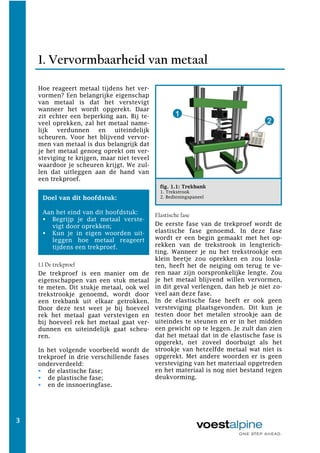
De trekproef is een manier om de
eigenschappen van een stuk metaal
te meten. Dit stukje metaal, ook wel
trekstrookje genoemd, wordt door
een trekbank uit elkaar getrokken.
Door deze test weet je bij hoeveel
rek het metaal gaat verstevigen en
bij hoeveel rek het metaal gaat ver-
dunnen en uiteindelijk gaat scheu-
ren.
In het volgende voorbeeld wordt de
trekproef in drie verschillende fases
onderverdeeld:
de elastische fase;
de plastische fase;
en de insnoeringfase.
fig. 1.1: Trekbank
1. Trekstrook
2. Bedieningspaneel
Elastische fase
De eerste fase van de trekproef wordt de
elastische fase genoemd. In deze fase
wordt er een begin gemaakt met het op-
rekken van de trekstrook in lengterich-
ting. Wanneer je nu het trekstrookje een
klein beetje zou oprekken en zou losla-
ten, heeft het de neiging om terug te ve-
ren naar zijn oorspronkelijke lengte. Zou
je het metaal blijvend willen vervormen,
in dit geval verlengen, dan heb je niet zo-
veel aan deze fase.
In de elastische fase heeft er ook geen
versteviging plaatsgevonden. Dit kun je
testen door het metalen strookje aan de
uiteindes te steunen en er in het midden
een gewicht op te leggen. Je zult dan zien
dat het metaal dat in de elastische fase is
opgerekt, net zoveel doorbuigt als het
strookje van hetzelfde metaal wat niet is
opgerekt. Met andere woorden er is geen
versteviging van het materiaal opgetreden
en het materiaal is nog niet bestand tegen
deukvorming.
2. 13
Plain strain
Plain strain is het omvormproces wat
we ook bij de trekproef zijn tegenge-
komen. We weten dus dat er tijdens
dit omvormproces rek - en daardoor
lengteverandering - in de hoofdrich-
ting plaats. Er is geen rek in de
dwarsrichting en dus ook geen ver-
lenging in die richting. Het plain
strain gebied (geel) vind je in de wan-
den van het bakje.
Wanneer we de platine met de vier
ronde gaten gaan bekijken, kunnen
we het volgende concluderen. De
gaatjes in de wand van het bakje
worden tijdens het trekken opgerekt
in de lengterichting, maar in de
dwarsrichting zijn ze nog net zo
breed als de gaatjes waarmee we be-
gonnen.
fig. 2.6 plain strain: lengteverandering
in de hoofdrichting, geen lengteveran-
dering in de dwarsrichting.
2.1.2 Versimpelen naar potje en bakje
Nu je alle omvormprocessen van het
potje en bakje kent, is het de kunst
om deze ook te herkennen en aan te
wijzen in de geometrie van elk wille-
keurig trekdeel. Het is namelijk zo
dat je elk trekdeel, hoe complex de
geometrie ook is, kunt herleiden naar
één of meerdere vlakken van het pot-
je of bakje. Kijk maar naar het vol-
gende voorbeeld.
fig. 2.7 Versimpelen naar bakje
Het herkennen van de omvormpro-
cessen in de geometrie van een trek-
deel vergt wel enige oefening, maar
zodra je het onder knie hebt, is het de
eerste stap naar het oplossen van een
defect. Door de geometrie van een
trekdeel te versimpelen naar een pot-
je of bakje kun je namelijk zeggen in
welk omvormproces het defect zit en
of het materiaal rondom het defect
teveel verdunt of verdikt. Want juist
die verdunning of verdikking van het
materiaal veroorzaken de defecten.
In de volgende paragraaf gaan we aan
de hand van het Forming Limit Dia-
gram (FLD) de mate van verdunning
en verdikking in elk omvormproces
verder toelichten.
3. 47
fig. 4.3 Vorm van de plooihouder
1. kromme plooihouder
2. rechte plooihouder
Tenslotte is het belangrijk dat de
looplijn niet te ‘hard’ staat. Hiermee
wordt bedoeld dat de looplijnen te
diep en te duidelijk zichtbaar zijn. Dit
kan onder andere worden veroorzaakt
door een te scherpe radius
Naast de vorm is de plaats van de
looplijn in het trekdeel erg belangrijk.
Looplijn mogen bijvoorbeeld bij bui-
tendelen alleen in het afvalgebied
zichtbaar zijn. Zodra er bij een bui-
tendeel een looplijn in het product
zichtbaar is, geldt dit als een afkeur.
Door de radii te wijzigen zal het begin
van de looplijn minder ‘hard’ in het
product staan.
4.2.1 Globaal, regionaal & plaatselijk inloopge-
drag
Inlooplijnen zijn dus een belangrijk
hulpmiddel bij het ‘lezen’ van het in-
loopgedrag en kunnen je helpen de
oorzaak van een defect te achterha-
len. Het indelen van een trekdeel in
verschillende regio`s kan je nog ver-
der helpen om op een gestructureerde
manier het inloopgedrag te beoorde-
len. We delen het trekdeel als volgt
op:
Globaal
Regionaal
Plaatselijk
Globaal
Een trekdeel globaal bekijken houdt in
dat je het inloopgedrag van het hele
deel beoordeeld (fig. 4.4). Je bekijkt
de inlooplijnen rondom en vergelijkt
bij een symmetrisch deel de beide
kanten met elkaar. Komt het defect op
meerdere plekken in het deel voor,
bijvoorbeeld plooien op elke hoek of
scheuren op elke hoek, dan heb je te
maken met een globaal defect.
Bij globale defecten moet je er van
uitgaan dat het gereedschap niet goed
is ingewerkt. Controleer in zo`n geval
het gereedschap met behulp van een
blauwdruk.
fig. 4.4 Globaal inloopgedrag
4. 02.09 | Isuzu N-truck 729
i | v | 01 | 2006
Go farther.
2 New electrical features: CAN-Bus
2.1 Introduction to CAN
The Isuzu N-truck 729 is the first Isuzu to use a
CAN-Bus system for exchange of information be-
tween different control units next to data exchanges
via "normal" separate wires.
The following unit explains the difference between
serial data exchange and the more conventional
data exchanges via separate wires known as "par-
allel" data exchange as well as features of the
Isuzu CAN-Bus system.
2.1.1 Data transmission between
control units
Data transmission can be achieved either by:
- Separate wires (parallel)
- CAN-Bus system (serial)
Separate wires
With parallel data exchange each piece of infor-
mation is exchanged over a separate wire. When
more information needs to be exchanged more
wires are used.
Parallel data exchange:
Each piece of information is exchanged over a separate wire.
The disadvantage of exchanging data in this man-
ner is that with an increasing quantity of informa-
tion, the number of wires also increases. This in-
creases the possibility for faults.
5. 02.010 Isuzu N-truck 729
Engine Mechanical features
Memo:
CAN-Bus system
A CAN-Bus can be visualised as an ordinary
coach. As a coach transports large quantities of
people between several locations, the CAN-Bus
transports large quantities of information between
several control units.
CAN-Bus
The CAN-Bus of the Isuzu N-truck 729 is an iso-
CAN system and uses two wires to exchange data.
The data is serially transmitted with a rate of 250
kb/sec.
Note:
Iso-CAN means it is a standardised
CAN-Bus protocol that is universally ac-
cepted in the automotive industry.
6. 02.011 | Isuzu N-truck 729
i | v | 01 | 2006
Go farther.
Memo:
2.2 CAN network
The following control units are part of the CAN-
Bus system of the N-truck:
- Engine Control Module (ECM)
- Electronic Hydraulic Control Unit (EHCU)
- Transmission Control Module (TCM)
- Data Memory Unit (DMU)
The control units are linked via the CAN-Bus and
form a network according to the following picture.
CAN network
1. Cut off resistor (discussed later on)
2. Joint connector CAN (discussed later on)
The following signals are communicated via the
CAN-Bus:
- Accelerator pedal position signal
- Engine output torque
- PTO control signal
- Exhaust brake cut signal
- Engine speed signal
- Injection volume reduction signal
- Clutch status signal
- Vehicale speed signal
Note:
Features of the Data Memory Unit are
discussed at the end of this unit.
7. 02.012 Isuzu N-truck 729
Engine Mechanical features
2.3 CAN-bus system operation
The CAN-Bus system is designed as a single pair
of wires; one blue and one blue white wire. The
blue/white wire is the so-called CAN-High and the
blue wire is called CAN-Low. Both are normal cop-
per wires with a cross-sectional area of 0.5 mm2.
The blue and blue/white wire are twisted and fea-
ture a plastic shielding merely to keep them to-
gether. This is not a coaxial shielding.
The wires are twisted to prevent electro-magnetic
interference to other units in the vehicle. Twisting
eliminates the magnetic fields that are created by
the rapid changes of the voltages on the CAN-
Bus. In the Wiring Diagrams the CAN wires are
easily identified by their colour and the twisted
wires symbol. Furthermore the CAN-high and
CAN-low lines are indicated with CAN-H and
CAN-L
CAN wires in the wiring diagram
1. Twisted wires
2. Symbol for CAN high and CAN low
8. 02.013 | Isuzu N-truck 729
i | v | 01 | 2006
Go farther.
Memo:
CAN-High has a voltage level that changes be-
tween 2.5 - 3.5 Volts and CAN-Low has a voltage
level that changes between 1.5 - 2.5 Volts.
Voltage level CAN high and CAN low
A. CAN high 2.5 - 3.5 Volts
B. CAN low 2.5 - 1.5 Volts
9. 02.014 Isuzu N-truck 729
Engine Mechanical features
The CAN-High and CAN-Low bus lines are at
both ends connected by a terminating resistor.
These terminating resistors have a value of 120
ohm each. They prevent the data from returning
as an echo after reaching the end of the line and
thus interfering the original data. The resistors are
located according to the picture. Please also notice
the joint connector CAN.
Cut off resistor & joint connector CAN
1. Cut off resistor
2. Joint connector CAN
10. 02.015 | Isuzu N-truck 729
i | v | 01 | 2006
Go farther.
2.4 CAN-bus service & diagnosis
Service & diagnosis of a N-truck equipped with the
CAN-Bus system is not that different from a N-truck
without the CAN-Bus system.
The operational status of the CAN-Bus is moni-
tored by the control modules. The control modules
expect a constant data flow from others module
that communicate via the CAN-Bus. If a control
module fails to receive expected data from each
module, DTC U2104, U2106 or U2108 is set de-
pending on what communication is lost.
CAN Related DTC
DTC DTC Name On Scan Condition for Condition for Suspected Cause
Tool Running the DTC Setting the DTC
U2104 CAN-Bus Reset - The ignition switch is - The ECM detects that - CAN high circuit is
Counter Overrun ON. the CAN-Bus OFF is short to ground, short to
detected. battery or ignition
voltage.
- CAN low circuit is short
to ground, short to
battery or ignition
voltage.
- Electrical interference.
- Faulty ECM.
- Faulty TCM.
- Faulty EHCU.
U2106 Lost CAN Commu- - The ignition switch is - The ECM detects that - CAN high circuit is
nications With ON. the CAN-Bus messages short to ground, short
Transmission Control from the TCM are not to battery or ignition
System being received. voltage.
- CAN low circuit is short
to ground, short to
battery or ignition
voltage.
- Electrical interference.
- Faulty ECM.
- Faulty TCM.
U2108 Lost Communications - The ignition switch is - The ECM detects that - CAN high circuit is
With ABS/TCS ON. the CAN-Bus messages short to ground, short
Control System from the EHCU (ABS to battery or ignition
control unit) are not voltage.
being received. - CAN low circuit is short
to ground, short to battery
or ignition voltage.
- Electrical interference.
- Faulty ECM.
- Faulty EHCU.
In this situation the TCM can also sets a CAN-Bus
DTC (U0100) when the
following condition is met.
- Receive: No CAN data input or data is
abnormal
- Send: No CAN data can be sent or data is
fault
As soon as the previous mentioned DTC`s are set,
the ECM illuminates the malfunction indicator lamp
(MIL). It is also possible that the Exhaust brake in-
dicator and/or the ASR indicator are illuminated
depending on what communication is lost.
11. 02.016 Isuzu N-truck 729
Engine Mechanical features
2.4.1 Tech 2
Although the ECM, TCM, DMU and the EHCU
communicate with each other via CAN-Bus, the
CAN link is not used for communication with the
scan tool. This is still done via Class 2 serial data
link as with previous models.
2.4.2 Data Memory Unit
The Data Memory Unit is a device connected to
the CAN-Bus which constantly records data of the
ECM, TCM and the EHCU. The DMU is located
just behind the radio and is used by Isuzu for
product improvement. Therefore it is not possible
for Isuzu retailers to communicate with the DMU
using the Tech 2. Communication with the DMU
can only be done by using a special interface box.
Location Data Memory Unit
1. Data Memory Unit
The DMU records to kinds of data:
- Accumulated data
- Logging data
Accumulated data shows the condition of the vehi-
cle throughout the operational life of the vehicle.
Logging data provides information on the vehicle
condition right before and after the ECM, TCM
and, in case of ABS, the EHCU have set a Diag-
nostic Trouble Code (DTC).
Note:
The DMU is of no influence on the nor-
mal operation and servicing or diagnos-
ing of the vehicle.