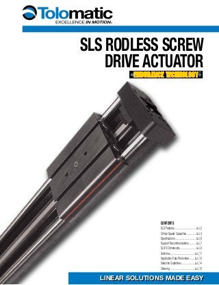
1. SLS Rodless SCREW
DRIVE ACTUATOR
LINEAR SOLUTIONS MADE EASYLINEAR SOLUTIONS MADE EASY
CONTENTS
SLS Features.........................................SLS_2
Critical Speed Capacities...................SLS_4
Specifications........................................SLS_6
Support Recommendations..............SLS_7
SLS10 Dimensions..............................SLS_9
Switches...............................................SLS_11
Application Data Worksheet............SLS_13
Selection Guidelines..........................SLS_14
Ordering................................................SLS_15
2. 1-800-328-2174
SLS_2 www.tolomatic.com
SLS rodless screw Drive ActuatorLook for this endurance technology
symbol indicating our durability design
features
This rodless style actuator is designed for carrying light to moderate loads on a wide, rigid base.
Based upon our LS pneumatic linear slide, it utilizes a guidance system consisting of two linear
guide rods with recirculating ball bearings for stable, smooth and low friction operation. Built-to-
order in stroke lengths up to 120 inches with multiple screw options available.
You can choose:
■ Solid nuts of bronze or
engineered resins offering
quiet performance at the
lowest cost; anti-backlash
available
■ Ball nuts offer positioning
accuracy and repeatability
with longer life; low-backlash
available
• High thrust bearing assembly design
isolates the motor from axial forces
•Precision machined table surface
provides a large surface area for
secure mounting
•Prevent contaminants from entering the
sealing band area to protect internal
components
• Four recirculating ball bearings
provide guidance, low friction
loss and long life
• Load and moments are
transmitted directly to the
actuator body
SCREW SUPPORT BEARINGS
WIDE TABLE SURFACE
FORMED END CAP WIPERS
LOAD-BEARING CARRIER DESIGN
MULTIPLE SCREW TECHNOLOGIES
3. 1-800-328-2174
SLS_3 www.tolomatic.com
You can choose:
■ Motor or gearbox supplied and
installed by Tolomatic
■ Specify the device to be installed
and actuator ships with proper
mounting hardware
■ Specify and ship your device to
Tolomatic for factory installation
LMI (inline) motor mount only
Carrier Options
■ Auxiliary Carrier Doubles the load
capacity and increases bending moments
capacity significantly
■ Metric Option
Provides metric tapped holes for mounting of
load to carrier and of actuator
■ Switches
Styles include: reed, hall-effect or triac. Select either
15ft potted cable with flying leads or 6in to quick-
disconnect coupler with mating 15ft cable
Options
• Bumpers protect the screw
and nut assembly from
damage at end of stroke
• Black anodized extrusion design is optimized for
rigidity and strength
• External switch channels on both sides allow
easy placement and adjustment of position
indicating switches
•Prevents contaminants from
entering the screw and nut
area for prolonged life
• Fatigue resistant stainless
steel bands are specifically
made to offer long life and
will not elongate
•Actuator base has
two T-Slot channels
running the entire
length for secure
mounting
• Table includes two
T-Slot channels for
easy attachment of
any load
TolOMatic…Linear solutions made easy
YOUR MOTOR HERE
EXTERNAL BUMPERS
Lightweight aluminum design
STAINLESS STEEL SEALING BAND
T-SLOT MOUNTING
4. 1-800-328-2174
SLS_4 www.tolomatic.com
B3S10SN05
0
20
40
60
80
100
120
140
160
170
180
0 2 4 6 8 10 12 14
SPEED (in/sec)
THRUST(lb)
1/2" 5TPI ACME Screw PV Limits
SLS10SN05
SLS10SN05
PV LIMITS: 1/2" 5 TPI US CONVENTIONAL ACME SCREW
B3S10SN/SNA02
0
20
40
60
80
100
120
140
160
170
180
0 5 10 15 20 25 30 35
SPEED (in/sec)
THRUST(lb)
1/2" 2TPI ACME Screw PV Limits
SLS10SN/SNA02
SLS10SN/SNA02
PV LIMITS: 1/2" 2 TPI US CONVENTIONAL ACME SCREW
B3S10SN01
0
20
40
60
80
100
120
140
160
170
180
0 10 20 30 40 50 60 70
SPEED (in/sec)
THRUST(lb)
1/2" 1TPI ACME Screw PV Limits
SLS10SN01
SLS10SN01
PV LIMITS: 1/2" 1 TPI US CONVENTIONAL ACME SCREW
1
10
100
1000
10,000
STROKE (mm)
SPEED(mm/sec)
0 500 1000 1500 2000 2500 3000
3048
3500
M3S10SN12
MAX THRUST*: 800 N
MLS10SN12
MAX THRUST*: 800 N
M3S10SN25
MLS10SN25
1549
1500
750
MAXIMUMSTROKEMAXIMUMSTROKE
MAXIMUMSTROKEMAXIMUMSTROKE
SLS10 Critical Speed for 12mm ACME, 12 and 25 LEADS
SLS/MLS10 ACME SCREW CRITICAL SPEED AND PV LIMITS
0
100
200
300
400
500
600
700
800
900
0 200 400 600 800 1000 1200 1400
1500
1600
MLS10 12mm 25mm Lead ACME Screw PV Limits
SPEED (mm/sec)
THRUST(N)
MLS10SN25
MLS10SN25
0
100
200
300
400
500
600
700
800
900
0 100 200 300 400 500 600 700
750
800
SPEED (mm/sec)
THRUST(N)
MLS 12mm w/12mm Lead ACME Screw PV Limits
MLS10SN12
MLS10SN12
120
85
MAXIMUMSTROKE
MAXTHRUST*: 130 LBMAXTHRUST*: 170 LB
B3S10SN02
SLS10SN05
BCS10SN02
SLS10SN02
12
60
30
SLS10 Critical Speed for .5 ACME, all TPI
0 20 40 60 80 100 140
STROKE (in)
SPEED(in/sec)
0.1
1
10
100
B3S10SN01
SLS10SN01
MAXIMUMSTROKEMAXIMUMSTROKE
CRITICAL SPEED WITH 1/2" US CONVENTIONAL ACME SCREW CRITICAL SPEED WITH 12mm METRIC ACME SCREW
SN = Solid Nut
SNA = Solid Anti-backlash Nut
* Maximum thrust is the maximum continuous
dynamic thrust subject to Thrust x Velocity limitation.
PV LIMITS: 12mm ACME METRIC SCREW w/25mm LEAD
PV LIMITS: 12mm ACME METRIC SCREW w/12mm LEAD
PV LIMITS: Any material which carries a sliding load is limit-
ed by heat buildup. The factors that affect heat generation
rate in an application are the pressure on the nut in pounds
per square inch and the surface velocity in feet per minute.
The product of these factors provides a measure of the
severity of an application.
SLS10 Rodless Screw Drive Actuator
ACME SCREW SPECIFICATIONS
P x V ≤ 0.1
( Thrust x Speed ≤ 0.1((Max. Thrust Rating)) ((Max. Speed Rating))
SIZING
ACTUATOR
www.tolomatic.com
5. 1-800-328-2174
SLS_5 www.tolomatic.com
SLS10 Rodless Screw Drive Actuator
BALL SCREW SPECIFICATIONS
BCS10 Critical Speed for .375 Ball Nut, 8TPI
120
STROKE (in)
SPEED(in/sec)
0 20 40 60 80 100 140
0.1
1
10
100
MAXTHRUST:* 130 LB
16
61
B3S10BN08
BCS10BN08
MAXIMUMSTROKEMAXIMUMSTROKE
MAXTHRUST*: 130 LB
CRITICAL SPEED WITH 3/8" US CONVENTIONAL BALL SCREW CRITICAL SPEED WITH 10mm METRIC BALL SCREW
STROKE (mm)
SPEED(mm/sec)
0 500 1000 1500 2000
0.1
10
100
1000
MAX THRUST:* 578 N406
1549
MCS10BN08
MLS10BN08
MAXIMUMSTROKEMAXIMUMSTROKE
MAX THRUST*: 578 N
SLS10: 3/8" Ball Screw Life Vs. Thrust
1
10
100
1,000
10,000
100,000
1,000,000
0 20 40 60 80 100 120 140
130
THRUST (lbs)
**LIFE(millionin)
B3S10BN/BNL08
SLS10BN/BNL08
MAXIMUMTHRUSTMAXIMUMTHRUST*
10
100
1,000
10,000
100,000
1,000,000
10,000,000
100,000,000
0 100 200 300 400 500 600
578
700 800 900
**LIFE(MILLIONmm)
THRUST (N)
MCS10BN08
MLS10BN08
MAXIMUMTHRUST*MAXIMUMTHRUST*
BN = Ball Nut
LIFE CALCULATION: 3/8" 8TPI US CONVENTIONAL BALL SCREW LIFE CALCULATION: 10mm METRIC BALL SCREW w/3.2mm LEAD
* Maximum thrust reflects 90% reliability for 1 million linear inches of travel.
SLS/MLS10 BALL SCREW SPECIFICATIONS
**Life indicates theoretical maximum life of screw only, under ideal conditions and does not indicate expected life of actuator.
SIZING
ACTUATOR
www.tolomatic.com
6. 1-800-328-2174
SLS_6 www.tolomatic.com
SLS10 Rodless Screw Drive Actuator
SPECIFICATIONS
SPECIFICATIONS RELATED TO ACTUATOR SIZE AND SCREW SELECTION
US CONVENTIONAL LEAD SCREWS
ACTUATOR SCREW SCREW
TPI
LEAD
BACKLASH
MAXIMUM
MAXIMUM INERTIA (lb-in2) BREAKAWAY
SERIES DIA. TYPE
(turns/ ACCURACY
THRUST*
STROKE BASE ACTUATOR PER/in TORQUE
(in) in) (in/ft) (in) (lb) (in) In Line OF STROKE (lb-in)
0.375 BN 08 0.004 0.015 130 61 0.0054 0.0005 1.063
0.375 BNL 08 0.004 0.002 130 61 0.0054 0.0005 1.063
0.500 SN 01 0.006 0.007 170 85 0.0554 0.0017 1.875
SLS10
0.500 SN 02 0.005 0.007 170 120 0.0262 0.0017 1.438
0.500 SNA 02 0.005 0.003 170 120 0.0262 0.0017 1.438
0.500 SN 05 0.006 0.007 170 120 0.0180 0.0017 1.250
SCREW CODE DESCRIPTION
SN Solid Nut
SNA Anti-backlash Solid Nut
BN Ball Nut
BNL Low-Backlash Ball Nut
Contact Tolomatic for higher accuracy and lower backlash options.
* For Acme screws, maximum thrust is the maximum continuous
dynamic thrust subject to Thrust x Velocity limitation. For ball
screws, maximum thrust reflects 90% reliability for 1 million linear
inches of travel.
METRIC LEAD SCREWS
ACTUATOR SCREW SCREW
LEAD
LEAD
BACKLASH
MAXIMUM
MAXIMUM INERTIA (kg-m2 x 10-6) BREAKAWAY
SERIES DIA. TYPE
(mm/
ACCURACY
THRUST
STROKE BASE ACTUATOR PER/mm TORQUE
(mm) turn) (mm/300) (mm) (N) (mm) In Line OF STROKE (N-m)
10 BN 3.2 0.13 0.38 578 1549 37.50 3.47 0.12
10 BNL 3.2 0.13 0.05 578 1549 37.50 3.47 0.12
MLS10
12 SN 12 0.13 0.18 800 3048 6.49 0.41 0.17
12 SN 25 0.13 0.18 800 1626 15.01 0.41 0.17
GENERAL ACTUATOR SPECIFICATIONS
SLS US CONVENTIONAL ACTUATORS
ACTUATOR CARRIER
BASE
WEIGHT PER/IN
TEMPERATURE
IP RATING*
SERIES WEIGHT (lb)
WEIGHT (lb)
OF STROKE (lb)
RANGE*
(Including Carrier) (F˚)
SLS10 1.54 6.05 0.404 40 - 130 44
MLS METRIC ACTUATORS
ACTUATOR CARRIER
BASE
WEIGHT PER/mm
TEMPERATURE
IP RATING**
SERIES WEIGHT (kg)
WEIGHT (kg)
OF STROKE (g)
RANGE*
(Including Carrier) (C˚)
MLS10 0.69 2.74 7.23 4 - 54 44
* Heat generated by the motor and drive should be taken into consideration as well as linear velocity and work
cycle time. For applications that require operation outside of the recommended temperature range, contact
Tolomatic.
** Protected against ingress of solid particles greater than .039 in (1mm) and splashing water.
LARGE FRAME MOTORS AND SMALLER SIZE ACTUATORS: Cantilevered motors need to be supported, if subjected to
continuous rapid reversing duty and/or under dynamic conditions.
SIZING
ACTUATOR
www.tolomatic.com
8. 1-800-328-2174
SLS_8 www.tolomatic.com
Breakaway torque will increase when using the Auxiliary carrier option. When ordering, determine your working stroke
and enter this value into the configuration string. Overall actuator length will automatically be calculated.
*Loads shown in table are at minimum “D” dimension, for ratings with longer “D” dimension see graph below
SLS10 Rodless Screw Drive Actuator
SPECIFICATIONS
AUXILIARY CARRIER: BENDING MOMENT AT ‘D’ DISTANCE
1100
1000
900
800
700
600
500
400
300
200
100
0
My/Mz(lb-in)
DIMENSION “D” (in)
124.3
113.0
101.7
90.4
79.1
67.8
56.5
45.2
33.9
22.6
11.3
0
My/Mz(N-m)
0 5 10 15 20 25 30
0 0.13 0.25 0.38 0.51 0.64 0.76
DIMENSION “D” (M)
MzMoment
MyMoment
MzMoment
MyMoment
“D”“D”
Rates shown on charts were calculated with these assumptions:
1.) Coupling between carriers is rigid.
2.) Load is equally distributed between carriers.
3.) Coupling device applies no misalignment loads to carriers.
* Customer must specify Dimension "D" (Distance between carrier center
lines) in configuration string.
DYNAMIC BENDING MOMENTS AND LOADS
MAXIMUM BENDING MOMENTS AND LOADS US CONVENTIONAL METRIC
SLS10 MLS10
Mx Moment (Roll) (lb-in : N-m) 80 9.0
My Moment (Pitch) (lb-in : N-m) 80 9.0
Mz Moment (Yaw) (lb-in : N-m) 125 14.1
Fz Load (Lateral) (lb : N) 100 445
SLS10 MLS10
Mx Moment (Roll) *(lb-in : N-m) 160 18.1
My Moment (Pitch) *(lb-in : N-m) 178 20.1
Mz Moment (Yaw) *(lb-in : N-m) 278 31.3
Fz Load (Lateral) (lb : N) 200 890
Minimum Dimension ‘D’ (in : mm) 5.5 169.7
STANDARD CARRIER
!
AUXILIARY CARRIER: Increases rigidity, load-carrying capacity and moments
SIZING
ACTUATOR
www.tolomatic.com
9. 1-800-328-2174
SLS_9 www.tolomatic.com
My (in.-lbs.)
DEFLECTIONIN'X'AXIS(in.)
0 20 40 60 80 100
0 2.3 4.5 6.8 9.0 11.3
0
0.0003
0.0006
0.0009
0.0012
0.0035
0
0.0076
0.0152
0.0229
0.0305
0.0381
DEFLECTIONIN'X'AXIS(mm)
My (N-m)
Mx (in.-lbs.)
DEFLECTIONIN'Y'AXIS(in.)
0 20 40 60 80 100
0 2.3 4.5 6.8 9.0 11.3
0
0.0005
0.0010
0.0015
0.0020
0.0025
0.0030
0.0035
0
0.0127
0.0254
0.0381
0.0508
0.0635
0.0762
0.0889
DEFLECTIONIN'Y'AXIS(mm)
Mx (N-m)
SLS10 Rodless Screw Drive Actuator
SPECIFICATIONS
F
MEASUREMENT DISTANCE: 6"
DEF.
Figures calculated with the following considerations:
1.) Tube supports spaced at minimum distances for each bore size
2.) Measurement distance from F to center of carrier is 6 inches
LOAD DEFLECTION
FMEASUREMENT DISTANCE: 8"
DEF.
Figures calculated with the following considerations:
1.) Tube supports spaced at minimum distances for each bore size
2.) Measurement distance from F to center of carrier is 8 inches
Y-AXIS DEFLECTION X-AXIS DEFLECTION
SIZING
ACTUATOR
www.tolomatic.com
DIMENSIONS
SLS/MLS10: IN-LINE MOUNT FOR BRUSHLESS MOTORS
AND GEARHEADS
Ø 1.504 (38.2)
x 0.15 (3.8) DP
#10-24 x 0.75 DP (M5 x 0.8) [4]
EQ SPACED ON
Ø 2.625 (66.7) BOLT CIRCLE
45°
Ø 1.40
(35.6)
2.49 (63.2) → MRV2x
2.24 (56.9) → GHJ20, GHJ21
2.80
(71.1)
2.80 (71.1)
1.34
(34.0)
Ø 1.40 (35.6)
Ø 0.22 THRU (4)
(5.6)
1.870 (47.5)
2.38 (60.5)
1.870 (47.5)
Ø 0.156 x 0.23 DP [2]
(4.0 x 5.8)
2.06
(52.3)
1.010
(25.7)
0.80
(20.3)
0.298
(7.6) For gearhead
dimensions and
specifications, refer to
literature #3600-4161
NOTE: MRB & MRV
motors are
discontinued contact
Tolomatic for
information on YMH
(Your Motor Here)
www.tolomatic.com
10. 1-800-328-2174
SLS_10 www.tolomatic.com
SLS10 Rodless Screw Drive Actuator
DIMENSIONS
SLS10/MLS10 ACTUATOR AND OPTIONS DIMENSIONS
CAUTION: DO NOT OVERTIGHTEN SWITCH
HARDWARE WHEN INSTALLING
FOR EXTENDED SHAFT
NOTE: The scored face of the switch indicates the
sensing surface and must face toward the magnet
KIT #0610-9066 Mounting Plate for use with 23 frame
KIT #0610-9067 Mounting Plate for use with 34 frame
KIT #0610-9010 Mounting PlateNOTE: Some actuators require switch
mounting on a specific side of the
actuator. Call Tolomatic 1-800-328-2174
OPTIONAL MOUNTING PLATES
OPTIONAL SWITCH MOUNTING
SENSING SURFACE
CL
STROKE
2.75
(69.8)
1.500
(38.10)
5.50
(139.7)
2.000 (50.80)
2.38 (60.3)
0.51 (12.9)
0.39 (9.8)
0.08
(2.0)
1.31 (33.3)
0.37 (9.4)
AA
SECTION A-A
2.000
(50.80)
Ø.250 x 0.200 DP
(6.0 x 5.1 DP)
0.472 (12.0)
2.500 (63.50)
0.75
(19.0)
0.85
(21.6)
0.59
(15.1)
1.149
(29.19)
#10-24 x 0.43 DP
(M5-0.8 x 11.0 DP)
#10-24 x 0.50 DP
(M5-0.8 x 24.1 DP)
0.95
(24.1)
4.25 (107.9)
1.000
(25.40)
4.75 (120.6)
0.82 (20.7)
2.07 (52.6)0.46 (11.7)
1.46 (37.1)
0.55 (13.8)
1.55 (39.2)
0.565
(14.35)
0.250
(6.4)
2.34 (59.4)
4.61
(117.2)
4.61
(117.2)
0.935
(23.75) 1.870
(47.50)
0.298
(7.57)
1.010
(25.65)
#10-24 UNC-2B x 0.50 DP [4]
(M5 x 0.8 x 12.7 DP)
Ø.157/0.159 x 0.28 DP [2]
(3.99/4.04 x 7.1 DP)
S(M)LS MOTOR MOUNTING
0.50 (12.7)
0.38 (9.5)
3.500 (88.90)
#10-24 x 0.63 DP
(M5-0.8 x 16.0 DP)
CL
SLOTS WILL ACCOMODATE
0.50 SQUARE NUT,
0.266 THICK MAX., 1/4-20
5.50 (139.7)
0.750 (19.05)
0.25 (6.4)
0.625 (15.9)
1.00 (25.4)
Ø .25 (6.4)
Ø .281 (7.1)
THRU [2]
Ø.270 THRU C'SINK Ø.531 x 82° [2]
(6.86 THRU C'SINK Ø13.5 X 82°)
Ø.281 THRU C'BORE Ø.44 x 0.28 DP [2]
(7.14 THRU C'BORE Ø11.2 x 7.1 DP)0.25
(6.4)
5.00 (127.0)
2.375
(60.3)
Unless otherwise noted, all dimensions shown are in inches (Dimensions in parenthesis are in millimeters)
www.tolomatic.com
11. 1-800-328-2174
SLS_11 www.tolomatic.com
SWITCHES
There are 10 sensing choices: DC reed, form A (open) or form C (open or
closed); AC reed (Triac, open); Hall-effect, sourcing, PNP (open); Hall-effect,
sinking, NPN (open); each with either flying leads or QD (quick disconnect).
Commonly used to send analog signals to PLC (programmable logic
controllers), TLL, CMOS circuit or other controller device. These switches are
activated by the actuator’s magnet.
Switches contain reverse polarity protection. QD cables are shielded; shield
should be terminated at flying lead end.
If necessary to remove factory installed switches, be sure to reinstall on the
same of side of actuator with scored face of switch toward internal magnet.
** WARNING: Do not exceed power rating (Watt = Voltage X Amperage). Permanent damage to sensor will occur.
*QD = Quick Disconnect; Male coupler is located 6" [152mm} from sensor,
Female coupler to flying lead (part #2503-1025) distance is 197" [5m] also see Cable Shielding specification above
RepLACeMeNT oF Qd SWITCheS MANUFACTURed BeFoRe JULY 1, 1997: It will be necessary to replace or rewire the female end coupler.
CAUTIoN: do NoT oVeR TIGhTeN SWITCh hARdWARe WheN INSTALLING!
CURReNT
Quick disconnect
Wiring
BROWN
BLACK
BLUE
+-
SIGNAL
oLd
Quick disconnect
Wiring
BROWN
BLACK
BLUE
+
-SIGNAL
†
Shielded from the female quick disconnect coupler to the flying leads. Shield should be terminated at flying lead end.
§
Maximum current 500mA (not to exceed 10VA) Refer to Temperature vs. Current graph and Voltage Derating graph
§§
Maximum current 250mA (not to exceed 3VA) Refer to Temperature vs. Current graph and Voltage Derating graph
Reed Switch Life expectancy: Up to
200,000,000 cycles (depending on load cur-
rent, duty cycle and environmental conditions)
DC REED, AC REED (TRIAC)
AND HALL-EFFECT
QUICK-DISCONNECT
COUPLER - MALE END
QUICK-DISCONNECT
COUPLER - FEMALE END
SpeCIFICATIoNS
Reed dC Reed AC hALL-eFFeCT dC
oRdeR Code R T R M B T B M C T C M T T T M K T K M
pART NUMBeR 3600-9082 3600-9083 3600-9084 3600-9085 3600-9086 3600-9087 3600-9088 3600-9089 3600-9090 3600-9091
LeAd 5m QD* 5m QD* 5m QD* 5m QD* 5m QD*
CABLe ShIeLdING Unshielded Shielded† Unshielded Shielded† Unshielded Shielded† Unshielded Shielded† Unshielded Shielded†
SWITChING LoGIC "A" Normally Open "C" Normally Open or Closed Triac Normally Open
PNP (Sourcing) Normally
Open
NPN (Sinking) Normally Open
MeChANICAL CoNTACTS Single-Pole Single-Throw Single-Pole Double-Throw Single-Pole Single-Throw NO, These Are Solid State Components
CoIL dIReCT Yes Yes Yes —
poWeR Led None
None None
None None
SIGNAL Led Red Red Red
opeRATING VoLTAGe 200 Vdc max. 120 Vdc max. 120 Vac max. 5 - 25 Vdc
oUTpUT RATING — — 25 Vdc, 200mA dc
opeRATING TIMe
0.6 msec max.
(including bounce)
0.7 msec max.
(including bounce)
— < 10 micro sec.
opeRATING TeMpeRATURe -40°F [-40°C] to 158°F [70°C] 0°F [-18°C] to 150°F [66°C]
ReLeASe TIMe 1.0 msec. max. — —
oN TRIp poINT — — 150 Gauss maximum
oFF TRIp poINT — — 40 Gauss minimum
**poWeR RATING (WATTS) 10.0 §
3.0 § §
10.0 5.0
VoLTAGe dRop 2.6 V typical at 100 mA NA — —
ReSISTANCe 0.1 Ω Initial (Max.) — —
CURReNT CoNSUMpTIoN —
1 Amp at
86°F [30°C]
0.5 Amp at
140°F [60°C]
200 mA at 25 Vdc
FReQUeNCY — 47 - 63 Hz —
CABLe MIN.
BeNd
RAdIUS
STATIC 0.630" [16mm]
dYNAMIC Not Recommended
SLS Rodless Screw Drive Actuator
12. 1-800-328-2174
SLS_12 www.tolomatic.com
PERFORMANCE
The NoTChed
FACe oF The
SWITCh INdICATeS
The SeNSING
SURFACe ANd
MUST FACe
ToWARd The
MAGNeT.
The NoTChed
GRooVe IN The
ACTUAToR
INdICATeS The
GRooVe To
INSTALL The
SWITCh. CONTACT
TOLOMATIC IF
SWITCHES ARE
REQUIRED ON
ANOTHER SIDE OF
ACTUATOR.
0
50
100
150
200
0 100 200 300 400 500
VOLTAGEA.C.orD.C.
CURRENT D.C (mA)
REED FORM A
REE
D
FORM C
TeMp. vs CURReNT, dC Reed VoLTAGe deRATING, dC ReedTeMp. vs CURReNT, AC Reed
0
100
200
300
400
500
600
0 20 40 60 80 100 120 140 160
LOADCURRENT(mA)
OPERATINGTEMPERATURE ( F)
REED FORM C
REED FORM A
0
200
400
600
800
1000
0 20 40 60 80 100 120 140 160
LOADCURENT(mA)
OPERATINGTEMPERATURE ( F)
TRIAC
RT & RM dC Reed, FoRM A
BT & BM dC Reed, FoRM C
CT & CM AC Reed, TRIAC
TT & TM hALL-eFFeCT, SoURCING, pNp KT & KM hALL-eFFeCT, SINKING, NpN
REED
SWITCH
LOAD
BROWN
BLUE(-)
(-)
(+)
(+)
REED
SWITCHLOAD
BROWN
BLUE(-)
(-)
(+)
(+)
OR
AC
COM
LOAD
INPUT
TRIAC
SWITCH
120Vac
Max.
MOV
BROWNBLUE
REED
SWITCH
COMMON
NORMALLY CLOSED
NORMALLY OPEN
BROWN
BLACK
BLUE
HALL-EFFECT
SOURCING
SWITCH
BLACK
LOAD
BROWN
BLUE(-)
(+)
(-)
(+)
HALL-EFFECT
SINKING
SWITCH
BROWN
BLACK
BLUE(-)
(+)
(-)
(+)
LOAD
WIRING dIAGRAMS INSTALLATIoN INFoRMATIoN
SLS Rodless Screw Drive Actuator
13. 1-800-328-2174
SLS_13 www.tolomatic.com
DISTANCE FROM dx ______
CENTER OF CARRIER dy ______
TO LOAD CENTER dz ______
OF GRAVITY
inch millimeter
(U.S. Standard) (Metric)
STROKE LENGTH _____________
inch (SK) millimeters
(U.S. Standard) (Metric)
NOTE: If load or force on carrier changes during cycle use
the highest numbers for calculations
LOAD _______________
lb. kg.
(U.S. Standard) (Metric)
COMPILE APPLICATION REQUIREMENTS
USE THE TOLOMATIC SIZING AND SELECTION SOFTWARE AVAILABLE ON-LINE AT
www.tolomatic.com OR... CALL TOLOMATIC 1-800-328-2174 with the above informa-
tion. We will provide any assistance needed to determine the proper MX actuator for the job.
APPLICATION DATA WORKSHEET
THRUST Fz ______
REQUIRED Fy ______
lbf. N
(U.S. Standard) (Metric)
BENDING MOMENTS Mx ______
APPLIED TO CARRIER My ______
in.-lbs. N-m Mz ______
(U.S. Standard) (Metric)
PRECISION
Repeatability __________________
inch millimeters
OPERATING ENVIRONMENT
Temperature, Contamination, etc.
___________________________________
___________________________________
___________________________________
CONTACT
INFORMATION
Name, Phone, Email
Co. Name, Etc.
Load attached to carrier OR Load supported by other mechanism
FRONT
VIEWβ
Lz
X
Z
SIDE VIEW
α
Lz
Y
Z
ACTUATOR
ACTUATORCARRIER
CARRIER
CENTER
OF GRAVITY
dz
d
Y
d
x
CENTER
OF GRAVITY
dz
d
Y
d
x
ACTUATOR
ACTUATOR
CARRIER
CARRIER
dx
CENTER
OF GRAVITY
CARRIER
ACTUATOR
CARRIER
ACTUATOR
d
z
d
z
d
Y
ACTUATOR
ACTUATOR
CARRIER
CARRIER
CENTER
OF
GRAVITY
dy
d
Z
dy
d
Zd
x
Horizontal Side Horizontal Down Vertical
ORIENTATION
Angled °
α __________ β ____________
MOVE PROFILE
Move Distance ________________
inch millimeters
Dwell Time After Move___________
Max. Speed __________________
in/sec mm/sec
MOVE TIME _____________
sec
NO. OF CYCLES _____________
per minute per hour
FAX 1-763-478-8080
Graph your most
demanding cycle,
including accel/decel,
velocity and dwell
times. You may also
want to indicate load
variations and I/O
changes during the
cycle. Label axes
with proper scale and
units.
MOTION PROFILE
+ Speed ( )
Time or Distance ( )
Fill in known data. Not all information is
required for all applications
-
SIZING
ACTUATOR
www.tolomatic.com
14. 1-800-328-2174
SLS_14 www.tolomatic.com
Selection guidelines
The process of select-
ing a load bearing actua-
tor for a given applica-
tion can be complex. It is
highly recommended that
you contact Tolomatic or
a Tolomatic Distributor for
assistance in selecting
the best actuator for your
application. The following
overview of the selection
guidelines are for educa-
tional purposes only.
1
COMPARE LOAD TO
MAXIMUM LOAD
CAPACITIES
Calculate the applica-
tion load (combination
of load mass and forces
applied to the carrier)
and application bending
moments (sum of all mo-
ments Mx, My, and Mz
applied to the carrier). Be
sure to evaluate the mag-
nitude of dynamic inertia
moments. When a rig-
idly attached load mass is
accelerated or deceler-
ated, its inertia induces
bending moments on the
carrier. Careful attention
to how the load is decel-
erated at the end of the
stroke is required for ex-
tended actuator perfor-
mance and application
safety. If either load or any
of your moments exceed
figures indicated in the
Moment and Load Capac-
ity table (pg. SLS_8) for the
actuator consider:
1) Higher capacity bearing
style
2) A different actuator style
(B3S, MXE, etc.)
3) Auxiliary carrier
4) External guide system
2CALCULATE LOAD
FACTOR LF
For loads with a center of
gravity offset from the carri-
er account for both applied
(static) and dynamic loads.
The load factor (LF) must
not exceed the value of 1.
=
Mxmax
LF
Mx +
Mymax
My +
Mzmax
Mz +
Fymax
Fy + < 1
Fzmax
Fz
If LF does exceed the value
of 1, consider the four choic-
es listed in step #2.
3
ESTABLISH YOUR
MOTION PROFILE
AND CALCULATE
Acceleration RATE
Using the application stroke
length and maximum carrier
velocity (or time to complete
the linear motion), establish
the motion profile. Select ei-
ther triangular (accel-decel)
or trapezoidal (accel-con-
stant speed-decel) profile.
Now calculate the maxi-
mum acceleration and de-
celeration rates of the
move. Speed should not
exceed critical speed value
as shown in graph (page
SLS_4-5) for the screw/nut
combination chosen. Also,
do not exceed safe rates of
dynamic inertia moments
determined in step #3.
4SELECT THE LEAD
SCREW
Based on the application
requirements for accuracy,
backlash, quiet operation,
life, etc. select the appropri-
ate lead screw type (Acme
screw with a solid nut or
ball screw with a standard
or anti-backlash nut) and
the pitch (lead). For addi-
tional information on screw
selection, consult “Which
Screw? Picking the Right
Technology” (#9900-4644)
available at www.tolomatic.
com.
5
SELECT MOTOR
(GEARHEAD IF
NECESSARY) AND
DRIVE
To help select a motor
and drive, use the sizing
equations located in the
Engineering Resources
section [ENGR] to calculate
the application thrust and
torque requirements. Re-
fer to Motor sections [MRV]
& [MRS] to determine the
motor and drive.
6
DETERMINE
T-nuts/
MOUNTING PLATE
REQUIREMENTS
• Consult the Support Rec-
ommendations graph for
the model selected (page
SLS_7)
• Cross reference the ap-
plication load and maxi-
mum distance between
supports
• Select the appropri-
ate number of T-nuts,
and mounting plates if
required for motor and
adapter clearance.
7CONSIDER OPTIONS
• Choose metric or inch
(US Conventional) load
mounting.
• Switches - Reed, Solid
State PNP or NPN, all
available normally open
or normally closed
SPEED FACTOR
For applications with high speed
or significant shock and vibration:
Calculated values of loads and bending
moments must be increased by speed factor
from the graph below to obtain full rated life
of profiled rail bearing system.
1.50
1.00
1.25
0.50
0.75
0 20
LOW
S H O C K A N D V I B R A T I O N
MEDIUMLOW
S H O C K A N D V I B R A T I O N
MEDIUM
40
0
1000
500
1500
60
LINEAR SPEED (in/sec)
LINEAR SPEED (mm/sec)
SPEEDFACTOR
1.50
1.00
1.25
0.50
0.75
SPEEDFACTOR
SIZING
ACTUATOR
www.tolomatic.com
15. 1-800-328-2174
SLS_15 www.tolomatic.com
SLS Rodless Screw Drive Actuator
ORDERING
Not all codes listed are
compatible with all options.
Use the Sizing Software to
determine available options
and accessories based on
your application requirements.
MODEL TYPE
SLS SLS Series US Conventional Screw Drive
MLS MLS Series Metric Screw Drive
MOTOR MOUNTING / REDUCTIONS
(must choose one)
LMI In-Line mounting
**LMX Extended shaft - old style (see note)
** For replacement actuators with extended
motor shafts purchased prior to 6/24/02
use LMX
SWITCHES
RM_ Reed Switch (Form A) with 5-meter
lead/QD (quick-disconnect), & quantity
RT_ Reed Switch (Form A) with 5-meter
lead, and quantity desired
BM_ Reed Switch (Form C) with 5-meter
lead/QD, and quantity desired
BT_ Reed Switch (Form C) with 5-meter
lead, and quantity desired
KM_ Hall-effect Sinking Switch with 5-meter
lead/QD, and quantity desired
KT_ Hall-effect Sinking Switch with 5-meter
lead, and quantity desired
TM_ Hall-effect Sourcing Switch with
5-meter lead/QD, and quantity desired
TT_ Hall-effect Sourcing Switch with
5-meter lead, and quantity desired
CM_ TRIAC Switch with 5-meter lead/QD,
and quantity desired
CT_ TRIAC Switch with 5-meter lead, and
quantity desired
TUBE BORE DIAMETER
10 1-inch (25 mm) bore
AUXILIARY CARRIER
DC_ _ Auxiliary Carrier, then center-to-center
spacing desired in decimal inches.
(Center-to-Center spacing will add to
overall dead length and will not
subtract from the stroke length
STROKE LENGTH
SK Stroke, then enter desired stroke length
in decimal inches
T-NUT OPTION
TN_ Additional T-nuts and quantity
MOUNTING PLATES
MP_ Mounting Plates plus quantity desired
FIELD RETROFIT KITS
ITEM SLS10 MLS10
1/4" Mounting Plates 0610-9010 0610-9010
1/2" Mounting Plates 0610-9045 0610-9045
B A S E M ODE L S PE C I F I C A T I O N S OP T I O N S S PE C I F I C A T I O N S
s L s 1 0 S n 0 2 s k 2 5 m p 2T N 4L M I d c 1 8 K T 2
NUT/SCREW CONFIGURATION
INCH (US Conventional) MODELS
SOLID NUT /
PITCH (turn/in) SERIES
SN01 SLS10
SN02 SLS10
SNA02 SLS10
SN05 SLS10
BALL NUT /
PITCH (turn/in) SERIES
BN08 SLS10
BNL08 SLS10
METRIC MODELS
SOLID NUT /
LEAD (mm/turn) SERIES
SN12 MLS10
SN25 MLS10
BALL NUT /
LEAD (mm/turn) SERIES
BN08 MLS10
BNL08 MLS10
NOTE: MRB & MRV
motors are
discontinued contact
Tolomatic for
information on YMH
(Your Motor Here)