Modellering af LAR anlæg samt modellering af stoffjernelse i LAR anlæg og bassiner
Morten Just Kjølby, DHI
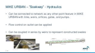
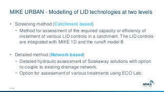
Modelleringen af forskellige LAR elementer i kombination med det traditionelle afløbssystem er blevet nemmere med den nye version af MIKE URBAN. DHI giver en præsentation af de nye muligheder i MIKE URBAN.
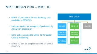
Hvilke koncentrationer af miljøfremmede stoffer kan der forventes efter at overfladevand har passeret gennem LAR-anlæg eller bassin? Der gives en præsentation af de nye muligheder, der er for modellering af stoffjernelse og –omsætning i LAR-anlæg og bassiner i MIKE URBAN. Med passende datagrundlag og kalibrering kan MIKE URBAN nu bruges til at vurdere koncentrationer af miljøfremmede stoffer efter at overfladevand har passeret gennem LAR-anlæg eller bassin.

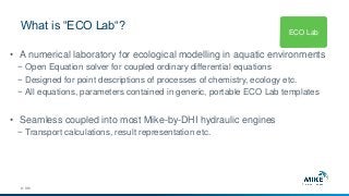
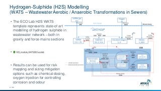
![MIKE URBAN – “Soakaway” infiltration formula
© DHI
h
Qin
Qof
Qf
Qof
Qin
l
w
𝑄 𝑓 = 𝐾(𝑙 ∗ 𝑤 + 2ℎ 𝑙 + 𝑤 )
𝑑ℎ
𝑑𝑡
=
1
𝑙∗𝑤∗𝜃
(𝑄𝑖𝑛 𝑡 − 𝑄 𝑓 𝑡 − 𝑄 𝑜𝑓 𝑡 )
𝑄 𝑓 = 𝐾𝑏𝑜𝑡𝑡𝑜𝑚 ∗ 𝐴 𝑠, ℎ=0 + 𝐾𝑠𝑖𝑑𝑒 ∗ (2 ∗ 𝐴 𝑐 + 2 ∗
𝑉𝑜𝑙
𝐴 𝑐
)
Definition and SI unit Symbol
Soakway porosity [-] θ
Field-saturated hydraulic conductivity [m/s], bottom Kfs, bottom
Field-saturated hydraulic conductivity [m/s], side Kfs, side
Water level (calculated by MIKE 1D) h
Surface Area As
Cross sectional Area Ac](https://image.slidesharecdn.com/4modelleringaflaranlg-170505175520/85/4-modellering-af-lar-anlaeg-26-320.jpg?cb=1494007082)
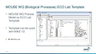
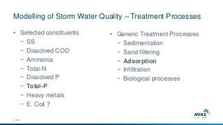
![Water level and Infiltration flow for various soil conductivities
© DHI
• Typical values for various soil
classifications
Soil classification Hydraulic Conductivity [m/s]
Gravel 1e
-3
to 0.1
Sand 1e
-5
to 1e
-2
Silt 1e
-9
to 1e
-5
Clay Below 1e
-9
to 1e
-2
“Moræneler” 1e
-10
to 1e
-6](https://image.slidesharecdn.com/4modelleringaflaranlg-170505175520/85/4-modellering-af-lar-anlaeg-28-320.jpg?cb=1494007082)