SlideShare a Scribd company logo
1 of 14
Download to read offline
Universal Guidelines for the
Divider Block
Lubrication Systems
Installation of
BY CURTIS ROYS
Atmospheric Rupture Assembly
on Back of Anchor Cross
S.S. Tubing
S.S. Liquid Filled
Pressure Gauge
Purge Port Connection
Lubricator Gear Box
Pressure Indicators
With Memory
Lubricator
Pump Non By-Pass
Low Pressure Filter
Master
Divider Valve Assembly
proflo
Divider Block Monitor
& Shutdown Protection
Oil Supply
Indicator
Port Plug
Piston
Enclosure
Plugs
Discharge Side
of Lube Pump
High Pressure
In-Line Filter
Injection
Check Valves
Cylinder or
Packing Gland
Injection points
Cylinder or
Packing Gland
Injection points
Injection
Check Valves
Secondary
Divider Valve Assembly
(All lubrication systems do not
require secondary divider valves)
Base Section
Discharge Check Valves
Set
Mode
T
C
C "PROTECTING COMPRESSORS WORLD WIDE"
Midland, Texas 1-800-664-4033
C. C. Technology Inc.
prO
flOCLASS I, DIV II
Groups A,B,C,D
NRTL/C
IrDA PORT
AVG 20
R
M o d e l - P F 1
US Copyright Registered 2001
500
1000
1500
2000
2500
3000II
IIIIIIII
IIIIIIIII
IIIIIIIII
IIII
IIIIIIII
IIIIIIIII
IIIIIIIII
II
T
C
C
CYCLE
TIME
DESIGN
SCHEMATIC
PRE-TESTING
COMPONENTS
PRE-TESTING
COMPONENTS
FINAL INSPECTION
DIVIDER BLOCK
INSTALLATION
DIVIDER BLOCK
INSTALLATION
TUBING
INSTALLATION
TUBING
INSTALLATION
CHECK VALVE
INSTALLATIONCHECK VALVE
INSTALLATION
NO-FLOW SHUTDOWN
3201 West Wall St. Midland, Texas 79701
Office: (432) 520-6700 Fax: (432) 520-6707
Toll free: 1-800-664-4033
Visit Us on the Web: www.cct.nu
email: curtis@cct.nu
INTRODUCTION:
There are many procedures that should be observed when installing “Positive Displacement, Single
Line Progressive Lubrication Systems”. This manual is intended for the person responsible for the
installation of the divider block system. It contains procedures to maintain the system integrity and
furnish the end user with a reliable divider block system.
This Installation Guide addresses the complete divider block system installation from tubing
installation to purging the system. The recommendations are specific to Single-Line Progressive
Systems for compressor applications.
Should the end user or person responsible for design of the divider block system have any questions
concerning this manual or the operation and maintenance of the divider block system please feel free
to contact CCTechnology at (432) 520-6700 , fax: (432) 520-6707 or email curtis@cct.nu.
CC Technology Divider Block Installation Guide:
Copyright (C) 2004 C CTechnologyInc.
All rights reserved. Printed in the United States of America. No part of this publication may be
reproduced in any part without written permission from the author. For information on lubrication
products ortoobtain copiesofthis publicationcontactC CTechnology.
Address: 3201WestWallSt.Midland,TX 79701
Phone:(432)520-6700 fax:(432)520-6700
E-mail:curtis@cct.nu
WebSite:www.cct.nu
GeneralGuidelinesforDividerBlock SystemInstallation:
TestingComponentsforReliableOperation
DesignSchematic
DividerBlockCycleIndicatorandCycleTime
Filters,LubeNo-FlowandShutdown Protection
FinalInspection.....................................................................................page2
SchematicDesignExample:
Position ofComponents:
ComponentInstallation:
MountingDividerBlocks:
Critical Components:
CheckValveInstallation:
Tubing Preparation:.............................................................................
Tubing Installation:
Purging Air From the System:
C C Technology Products.................
................................................................page3
......................................................................page 4
.......................................................................page 4
DividerBlockInstallation:
MasterDividerBlockInstallation:
SecondaryDividerBlockInstallation:
.....................................................................page 4&5
...........................................................................page 6
.....................................................................page 7
page 8
..............................................................................page 9-11
..............................................................page 12
....... ............................................Back Cover
Purge and Pre-Lube Connection:
Pressure Gauges:
Atmospheric RuptureAssembly:
In-line Filters:
Lube No-Flow Shutdown:
Check Valves:
Base Plate Check Valves:
Injection Check Valves:
T CABLE OF ONTENTS
Visit Us On the Internet www.cct.nu
1
GENERAL GUIDELINES FOR DIVIDER BLOCK SYSTEMS
A. TESTING COMPONENTS FOR RELIABLE OPERATION:
Every component of the divider block system must be assembled and tested before shipping to the
installation site.
Every divider block system is designed for installation on a specific compressor.
This ensures each component functions correctly and conforms to manufacturers
specifications. Testing the assembled components before shipping eliminates possible on-site problems
with the system after installation or during start-up. All components that are shipped unassembled should
be accompanied with literature for specific assembly, testing and operating instructions.
The lube system installer must always have a certified schematic of the divider block system designed by a
qualified person.
Each lube system design is based on various gas stream components, pressures and temperatures. When
designing the divider block system the design engineer must consider not only gas stream components,
but variables for lubrication rates due to materials used for the compressor rod, packing gland, cylinder and
ring components. The schematic diagram should illustrate all tubing runs from each divider block to the
injection point it is intended to serve. It should also include specific lube rates to individual injection points
and all components needed to complete the installation of the system. (see figure "A" )
B. DESIGN SCHEMATIC:
CC Technology Divider Block Installation Guide:
C. CYCLE INDICATOR AND CYCLE TIME:
D. FILTERS and LUBE NO-FLOW SHUTDOWN PROTECTION:
E. FINAL INSPECTION:
The lubrication system must include a device to indicate each cycle of the divider block system to
set and monitor lube rates.
To eliminate excessive wear the lube rates
should be doubled for a minimum of 200 hours for new or rebuilt compressors.
The lube system design must always include specifications for low and high pressure in-line
filters
A no-flow shutdown device must be installed on every
divider block system, connected to the control panel and tested for operation, to ensure
shutdown protection for the compressor in the event of lube system failure
always re-check each
component of the system
There should never be any changes made to the
divider block design system without approval of the engineer responsible for the system design.
(see proflo monitor figure”A” The lube system design must include a
suggested cycle time of the master divider block. The suggested cycle time allows the operator to set lube
rates of the system for normal operation of the compressor. Lube rates should be doubled for break-in of
the compressor components when starting up a new or freshly over hauled compressor. The compressor
operator must adjust the lubricator pump until the divider block is cycling at the suggested cycle time to
prevent premature failure of the compressor components.
to avoid problems caused by contaminated lubricants, debris left in components during assembly
or trash from open containers or reservoirs.
. (see figure "A”)
After installation of the divider block system is completed, the installer should
including divider block sizes and tubing runs to ensure all lubrication points
are being serviced by the correct divider block.
3201 West Wall St. Midland, TX 79701 (432) 520-6700 1-800-664-4033 fax: (432) 520-6707
2
Pressurized Filtered Oil
Atmospheric Rupture Assembly
(Purple Disc) Torque to 36 Inch Pounds
“DO NOT PLUG”
0-391040R
Ariel Pressure Cross Assembly
W/ S.S. Liquid Filled Pressure Gauge
Purge Port & Atmospheric Rupture Assy.
0-391040L
Ariel Pressure Cross Assembly
W/ S.S. Liquid Filled Pressure Gauge
Purge Port & Atmospheric Rupture Assy.
Purge Port Connection
Lubricator Gear Box
Replace Oil & Check For Wear
Every 12 Months
(2) CCT 0-92377
3/8” Lubricator Pump
Roller Rocker
ALEMITE-L
Pressure Test
Every 12 Months
15.98 PPD
20.80 PPD
500
1000
1500
2000
2500
3000II
IIIIIIII
IIIIIIIII
IIIIIIIII
IIII
IIIIIIII
IIIIIIIII
IIIIIIIII
II
500
1000
1500
2000
2500
3000II
IIIIIIII
IIIIIIIII
IIIIIIIII
IIII
IIIIIIII
IIIIIIIII
IIIIIIIII
II
T
C
CT
C
C
0-391042A
CCT-0-509052
High Pressure
10 Micron In-line Filter
Replace Element #EK9052
Every 12 Months
15.98
AVG 11.2
6
Pints Per Day
LCD Should Display Sec. For Recommended Lube Rates
@ Rated RPM
Overhaul Break-in Cycle Time Seconds for 200 Hours
RPM
1500 11.2
1400 12.0
1300 12.9
1200 14.0
1500 18.0
1400 19.2
1300 20.7
1200 22.5
RPM vs. Cycle Time
Compressor Divider Block
Cycle Time Sec. RPM
Divider Block
Cycle Time Sec.
CCT-0-750014-1/4”
Ultra Check Valve
at Each Injection Point
0-T302500
Pressure Indicators
13.50” PKG- 2.40 PPD
13.50” CYL- 4.00 PPD
18 T
30 T
13.50” PKG- 2.40 PPD
13.50” CYL- 4.00 PPD
30 T
1-800-337-3412
ODESSA, TEXAS
Set
Mode
T
C
C "PROTECTING COMPRESSORS WORLD WIDE"
Midland, Texas 1-800-664-4033
C. C. Technology Inc.
prO
flOCLASS I, DIV II
Groups A,B,C,D
NRTL/C
IrDA PORT
PRO FLO
R
M o d e l - P F 1
US Copyright Registered 2001
1-800-337-3412
ODESSA, TEXAS
Set
Mode
T
C
C "PROTECTING COMPRESSORS WORLD WIDE"
Midland, Texas 1-800-664-4033
C. C. Technology Inc.
prO
flOCLASS I, DIV II
Groups A,B,C,D
NRTL/C
IrDA PORT
PRO FLO
R
M o d e l - P F 1
US Copyright Registered 2001
CCT-0-750014-1/4”
Ultra Check Valve
at Each Injection Point
0-T302500
Pressure Indicators
9.750” CYL- 6.38 PPD
6.375” PKG- 2.40 PPD
9 T
9.750” PKG- 2.40 PPD
6.375” CYL- 4.80 PPD
12 S
9 S
20.80
AVG 18.0
9
Pints Per Day
LCD Should Display Sec. For Recommended Lube Rates
@ Rated RPM
Overhaul Break-in Cycle Time Seconds for 200 Hours
SCHEMATIC DESIGN EXAMPLE Figure "A"
RPM vs. Cycle Time
3201 West Wall St. Midland, TX 79701 (432) 520-6700 1-800-664-4033 fax: (432) 520-6707
Proflo Pf1
Divider Block Monitor
and Lube No-Flow
Shutdown Device
CC Technology Divider Block Installation Guide:
3
Compressor
3201 West Wall St. Midland, TX 79701 (432) 520-6700 1-800-664-4033 fax: (432) 520-6707
CC Technology Divider Block Installation Guide:
A. POSITION OF COMPONENTS:
B. COMPONENT INSTALLATION:
1. Gearbox and Pump Installation:
C. DIVIDER BLOCK INSTALLATION:
Master Divider Block Installation:
1.
Secondary Divider Block Installation:
2.
D. MOUNTING DIVIDER BLOCKS:
1.
Positioning of components on the compressor is essential
Never install unnecessary conduit, piping, electrical connections or objects that will prevent the
operator from having access to the lubricator pump and gearbox.
to ensure the trouble free operation of any
centralized lubrication system. If the correct components have been designed and selected, improper
installation will make it difficult to access the system for purging air from the system or to replace components
when preventive maintenance is performed.
If the compressor does not have a specific mounting bracket for the lubricator reservoir, install the pump
gearbox in an area on the compressor that is easy to access and not subjected to heavy traffic or debris. Easy
access is necessary to enable the operator to adjust lubrication rates and to check the gearbox for correct oil
levels.
Install the master divider block (the first divider block downstream of the pump) as
close to the pump as possible. This will allow the operator to adjust the lubricator pump while
monitoring cycle time of the system to achieve correct lubrication rates.
Install secondary divider blocks as close as possible to the injection points on the compressor
cylinders and rod packing. This procedure eliminates long tubing runs from the divider block to the
injection points and enables the operator to easily inspect the system for tubing leaks.
Mount all divider blocks parallel to the floor. This allows complete purging of air from the system and
makes it easier to install straight and plumb tubing runs. (See Figure "B" Below)
6 S
6 S
6 T
6 S
6 S
6 T
INCORRECT MOUNTING CORRECT MOUNTING
Divider Block Mounted Parallel to FloorDivider Block Not Mounted Parallel to Floor
Figure "B”
4
3201 West Wall St. Midland, TX 79701 (432) 520-6700 1-800-664-4033 fax: (432) 520-6707
CC Technology Divider Block Installation Guide:
D. Mounting Divider Blocks Continued:
2.
3.
4.
5
6.
7.
CAUTION:
8.
9.
10.
Avoid installing the divider blocks in locations that prevent easy access for preventative
maintenance or replacement.
The indicator port plugs on the front of the divider blocks should be easily accessed for trouble
shooting the system for blockage and for ease of replacement.
The divider blocks may be mounted directly to the compressor frame, if the surface can be drilled
and tapped. When mounting the divider blocks directly to the cylinder, “
Mount all divider blocks on a flat surface wherever possible. Mounting to an uneven surface may
cause distortion in the piston bores and create premature wear or failure.
Use properly sized bolts for mounting the divider blocks to the compressor frame.
Use divider block mounting brackets in areas that require the divider block to be raised from the
mounting surface to enable reliable tubing installation. CC Tech has several styles of mounting
brackets to ensure correct mounting of the divider blocks
When using a mounting plate that must be welded in place, “
Heat or sparking generated during welding will
permanently damage the divider blocks.
Install all divider block assemblies in an area on the compressor to avoid damage from debris or
dropped objects.
Install the tubing on the compressor frame away from common areas that must be accessed for
maintenance and out of areas commonly used for stepping or where there is the possibility of
damage from debris or dropped objects.
Keep all multiple tubing runs from secondary divider blocks as short as possible to reduce total
lubricant volume held in the lines to the injection points.
DO NOT” use long drill bits
that can penetrate through the inside wall of the compressor cylinder.
NEVER” weld on a
mounting plate with the divider block installed.
5
E. CRITICALCOMPONENTS:
1. Purge and Pre-Lube Connection:
2. Pressure Gauges:
Atmospheric RuptureAssembly:
4. In-line Filters:
Always install a purge port connection on the discharge side of the pump
The purge port connection must incorporate a check valve
Proper purging of air from the divider block system before compressor start-
up is critical for reliable and trouble free operation of the system.
It is absolutely necessary to install pressure gauges on all divider block systems
Atmospheric rupture assemblies must be installed on every divider block system
Every system must have in-line filters with a minimum of 25 micron filtration to prevent
contamination and failure of the lube pump and divider blocks.
to allow purging air
from the tubing lines before compressor startup or after any maintenance is performed on the divider
block system.(see figure “ ”) to keep
oil from blowing out of the system and allowing air to enter the system when removing the purge gun. If
no check valve is in place air will enter the system when removing the purge gun. Trapped air can
cause phantom shutdowns of the compressor and has the same indications as divider block failure or
trash in the system.
(See page 12)
to enable
the operator to monitor system pressure and operation of the divider block system. (see figure “ ”).
to release
pressure if blockage occurs in the system. The relieving of oil flow to atmosphere enables the lube no-
flow to shutdown the compressor. The compressor will never shutdown if an atmospheric assembly is
not installed or if the atmospheric rupture assembly has been plugged. (see figure " ”)
It is recommended to install both a
low pressure pre-filter before the pump and high pressure in-line filter downstream of the lube pump.
Install all in-line filters in an area that can easily be accessed for filter changes or cleaning at
recommended maintenance intervals. (see figure " ”)
3.
C-1
C-2
C-3
C-4
3201 West Wall St. Midland, TX 79701 (432) 520-6700 1-800-664-4033 fax: (432) 520-6707
CC Technology Divider Block Installation Guide:
500
1000
1500
2000
2500
3000II
IIIIIIII
IIIIIIIII
IIIIIIIII
IIII
IIIIIIII
IIIIIIIII
IIIIIIIII
II
500
1000
1500
2000
2500
3000II
IIIIIIII
IIIIIIIII
IIIIIIIII
IIII
IIIIIIII
IIIIIIIII
IIIIIIIII
II
T
C
CT
C
C
0-391042A
( )
CCT-0-509052
High Pressure
In-line Filter
10 Micron
C-4
( )
Purge Port
Connection
C-1
( )
Atmospheric
Rupture
Assembly
C-3
( )
Pressure
Gauge
C-2
High Speed Separable Compressor
Model 55 Type Lubricator
Figure "B"
1725 RPM -1HP
Model # 3546-230-460
TEFC ELECTRIC MOTOR
B-118
( )
1211-B-118
Low pressure
In-Line Filter
C-4
( )
0-2Z763-9
Filter Primer
C-4
lincoln modular lube
8 : 1
C C Technology
21.5:1
500
1000
1500
2000
2500
3000II
IIIIIIII
IIIIIIIII
IIIIIIIII
II
T
C
C
( )
Atmospheric
Rupture Assembly
on Back of PCA
C-3
Slow or High Speed Compressor with
Electric Driven HVLP Lube Pump and Gear Box
To Master
Divider Block
From Oil Supply
( )
Purge Port
Connection
C-1
( )
Pressure
Gauge
C-2
6
E. CRITICALCOMPONENTS CONTINUED:
5. Lube No-Flow Shutdown:
F. Check Valves:
1. Base Plate Check Valves:
The lube no-flow device is the only shutdown protection for the compressor if the pump fails or
blockage occurs in the system.
Operating pressure of the check valve must be appropriate for working pressure of the system.
to increase the dependability and fluid movement of the divider block piston. Base plate check
valves prevent introduction of gas or air into the hydraulic circuit of the divider block if the injection
check valve should fail.
“DO NOT” operate any divider block system without a lube no-flow shutdown device.
All divider block systems must have a check valve installed at each injection point.
Install base plate check valves (termed Reverse Checks) on each working outlet of the base
plate
2. Injection Check Valves:
Check valves must be installed on all lubrication points
For reliable operation “DO NOT” install the injection check valves in a vertical position.
as close as possible to the injection
point.
C
Vertical installation can allow the
introduction of hot, contaminated gas into the check valve every time the valve opens to inject oil into
the lubrication point. The gas migrating into the check valve as it opens and closes can also cause
possible coking of oil on the ball and seat of the check valve causing premature failure. (See figure "D”)
heck
valves should be installed in a manner as to permit a minimum of 1” of oil head above the check valve.
The 1" of oil head will allow a liquid seal in the check valve and keep the heated gas and debris
separated from the check valve seat for increased reliability.
CC Technology Divider Block Installation Guide:
Cylinder
1”
MINIMUM
LIQUID SEAL
RECOMMENDED
Check Valve
1”
Cylinder
Check Valve
NOT RECOMMENDED RECOMMENDED
Cylinder
Check Valve
Cylinder
1”
MINIMUM
LIQUID SEAL
RECOMMENDED
Check Valve
1”
Check Valve Installation
Using the CC Tech
Oil Head Adapter
1”
Cylinder
Check Valve
Oil Head
to Protect
Check Valve
Sealing Surface
Oil
Figure "D”
3201 West Wall St. Midland, TX 79701 (432) 520-6700 1-800-664-4033 fax: (432) 520-6707
7
A. TUBING PREPARATION
1. Cleaning Tubing and Piping:
2. Tubing Flushing Procedure:
3. Cutting the Tubing:
When installing the divider block system,
. The initial startup of the divider block system is
the most critical time. Any debris or contamination that is present in the hydraulic system will
cause immediate or premature failure of the divider block components. If debris is present in the
system during initial startup it will be carried through the hydraulic circuit and deposited in the
divider block pistons, check valves and rod packing or directly into the compressor cylinder. If
debris in the hydraulic system does not cause immediate damage to the system components,
the existing particles can cause premature failure of the system due to degradation of the
components caused by wear.
1. If the ends of the tubing have been left open to the environment all tubing should
be flushed with high-pressure water to remove any debris that could be present
from transportation to the job site or during storage .
2.After loosening the debris with high pressure water washing, insert an air gun in the end of the
tubing and blow out the loose debris.Always use clean filtered air. (see figure "E")
If the tubing is to be stored for any length of time, the ends should be capped to prevent
contamination.
1. All tubing should be cut with industry standard tubing cutters such as the one in figure “F”
designed to be used with stainless steel tubing. The cutting wheel must be sharp to obtain a
smooth square cut.
2. After cutting the inside and outside of the tube end must be de-burred and cleaned to prevent
metal particles from entering the lubrication system damaging the lube pump, divider blocks, or
compressor components. It is recommended to use a de-burring tool such the one in figure "G”.
all tubing and piping must be thoroughly cleaned
to assure reliability of the lubrication system
For reliable operation of the divider block system it is extremely important to avoid any
introduction of foreign debris in the hydraulic circuit or tubing lines.
3201 West Wall St. Midland, TX 79701 (432) 520-6700 1-800-664-4033 fax: (432) 520-6707
Figure "G”Figure "E”
CC Technology Divider Block Installation Guide:
8
Figure "F”
B. TUBING INSTALLATION:
1. Routing of Tubing Bends:
2.Avoid Excessive Strain on Joints:
The divider block system schematic designates the points on the compressor to be lubricated and the
exact divider block that should be connected to each injection point.The schematic must be followed as
per the drawing but it does not identify the paths to follow due to differences in compressor frames and
installations. The basic rule to remember when installing tubing is to keep all lines as short as possible
with a minimum number of bends. By reducing the number of bends you reduce the pressure drop in
the hydraulic system. The installer should remember the operator must maintain the compressor and
the tubing installation should not interfere with everyday tasks of preventative maintenance performed
on the compressor.
The most logical path and related guidelines are demonstrated in the illustrations
on the following pages.
A. Short tubing runs
should incorporate a bend to allow removal of the tubing to compensate for expansion and contraction
caused movement generated in a pressurized system. (see figure "H")
B. - Use a “U" bend in long lines to allow for expansion.
Strained joints in tubing bends will eventually leak. (see figure "H")
Routing of tubing is the most difficult but most significant of the installation
considerations. Proper routing involves installing tubing from one point to another through the
most logical path.
Avoid straight short tubing runs. A strained joint will eventually leak.
Allow for expansion and contraction
INCORRECT ROUTING
INCORRECT ROUTING
CORRECT ROUTING
CORRECT ROUTING
Figure "H”
INCORRECT ROUTINGCORRECT ROUTING
3201 West Wall St. Midland, TX 79701 (432) 520-6700 1-800-664-4033 fax: (432) 520-6707
CC Technology Divider Block Installation Guide:
9
B. TUBING INSTALLATION CONTINUED:
3. Install tubing around obstructions without excessive 90 bends:
4. Do not install tubing on walkways or in areas where it could present a safety hazard.
5. Keep tubing lines away from any components that require maintenance:
6. Follow the shape of the object or surface with tubing bends:
o
Pressure drop due to one 90 bend is greater than two 5
o
bends. (see figure "I")
1.Do not install tubing where it could be damaged by operators performing everyday preventative
maintenance. Tubing lines that are installed over the top of, or next to components that must be accessed for
maintenance will be moved or bent to enable the operator to access the component. Bending the tubing by
force to access components could cause leaks or failure of the tubing connections.(see figure "J")
1.Install tubing to conform to surfaces or objects as close as possible. Installation of tubing lines that
stand out away from objects are easily damaged and create possible safety hazards.(see figure "K")
Figure "I”
Figure "J”
INCORRECT ROUTINGCORRECT ROUTING
Figure "K”
INCORRECT ROUTINGCORRECT ROUTING
3201 West Wall St. Midland, TX 79701 (432) 520-6700 1-800-664-4033 fax: (432) 520-6707
CC Technology Divider Block Installation Guide:
10
B. TUBING INSTALLATION CONTINUED:
7. TubingAppearance:
8. Securing and Supporting Tubing:
Tubing lines should have a clean and orderly appearance to allow the operator to easily troubleshoot the
system for leaks and perform repairs. (see figure "L")
Multiple tubing lines should not be left suspended in mid-air
without securing them together using tubing clips with back plates for support. Tubing clips are used to secure
multiple tubing lines together eliminating vibration against each other. Tubing left unsupported could eventually
leak due to vibration. Vibration could cause the fitting to loosen or create fatigue in the tubing which will lead to
the tubing splitting and leaking. Tubing can be clamped individually or in sets from 2 to 12 lines.
o ensure reliable trouble free service of the divider
block system and protect the compressor from possible premature wear due to insufficient lubrication. (see
figure "M")
To ensure orderly appearance of the tubing and reliability of the divider block system all tubing lines
must supported and secured after installation.
Use sufficient
tubing clips to properly support and secure the tubing t
Figure "L”
INCORRECT ROUTING
No Tubing Clips
CORRECT ROUTING
with Proper Tubing Clips
Figure "M”
VERTICAL TUBING SUPPORT
With Tubing Clips and Back Plates
HORIZONTAL CLAMPING
Directly to the Compressor Frame
3201 West Wall St. Midland, TX 79701 (432) 520-6700 1-800-664-4033 fax: (432) 520-6707
CC Technology Divider Block Installation Guide:
11
C. Purging Air from the System and pre-lubing the
components:
Divider block systems operate correctly only when all tubing lines and
components are completely filled with oil to eliminate air in the system.
The operator should always pre-lube the divider block system and
components before the compressor is started.
1. After the lubrication system is installed, it is necessary to
purge air from all components, (tubing, divider blocks, check
valves) and fill the entire system with oil that will be used to
lubricate the compressor components during normal operation.
Model # 382510-3
Lubrication System Purge Gun
The divider block system should always be purged of air and pre-lubed if any components are
removed or loosened after the initial installation and start-up of the compressor. Although divider block
systems can eventually self purge, this severely delays purging air from the divider blocks, tubing and filters
and can result in erratic operation of the system and cause phantom shutdowns and premature wear or failure
of compressor components.
Purge Gun
Pump in
Vertical Position
(5) Purge Port
with Check Vakve
1/4”
S.S. Tubing
(6) Discharge Side
of Lube Pump
Tubing
Connection
(4)
Secondary
Divider Valve
Inlet
(2 & 3)
Tubing
Connections
Cylinder
or
Packing Gland
Injection Points
(1) Tubing Connection
Master Divider Valve Inlet
Follow this procedure after installation of the divider block system is completed or when any components are
replaced, removed or any maintenance is performed on the system.
Step 1:
Step 2:
Step 3:
Step 4:
Step 5:
Step 6:
Step 7:
Step 8:
The lubrication system is now ready to operate.
After installation of the lube system and before compressor
start-up loosen all tubing connections at the inlet of the master
divider valve (1),
. If there are secondary divider valves (4) loosen
tubing connections at the inlet of the secondary divider valves .
If a purge port (5) is available at the pump head connect the
purge gun. If no purge port is available remove the tubing from the
discharge side of the pump (6) and connect the purge gun to the
tubing.
Pump clean oil common to the system into the tubing line
until there are no air bubbles observed flowing from the tubing
connection at the inlet of the master divider valve. Always hold
purge gun in a vertical position to eliminate pumping air into the
system.
Tighten the tubing connection at the inlet of the master
divider valve while oil is still flowing.
Continue to operate the purge gun until no air bubbles are
observed flowing from the tubing connection at the inlet of the
secondary divider valve.
Tighten the tubing connection at the inlet of the secondary
divider valve while oil is still flowing.
Continue to operate the purge gun until there are no air
bubbles observed flowing from the tubing connections at the
cylinder or packing gland injection points.
Tighten the tubing connections at the cylinder and packing
gland injection points while oil is still flowing.
cylinder injection points (2) and packing gland
injection points (3)
5001000
1500 2000
25003000
T
C
C
3201 West Wall St. Midland, TX 79701 (432) 520-6700 1-800-664-4033 fax: (432) 520-6707
(2 & 3)
Tubing
Connections
Cylinder
or
Packing Gland
Injection Points
CC Technology Divider Block Installation Guide:
12

More Related Content

What's hot (10)

10.Engine parts
10.Engine parts10.Engine parts
10.Engine parts
 
9.Steering & controls
9.Steering & controls 9.Steering & controls
9.Steering & controls
 
Civic1500 Turbocharging
Civic1500 TurbochargingCivic1500 Turbocharging
Civic1500 Turbocharging
 
Caterpillar cat 322 c fm excavator (prefix cby) service repair manual (cby000...
Caterpillar cat 322 c fm excavator (prefix cby) service repair manual (cby000...Caterpillar cat 322 c fm excavator (prefix cby) service repair manual (cby000...
Caterpillar cat 322 c fm excavator (prefix cby) service repair manual (cby000...
 
Caterpillar cat 235 b excavator (prefix 9pc) service repair manual (9pc00001...
Caterpillar cat 235 b excavator (prefix 9pc) service repair manual  (9pc00001...Caterpillar cat 235 b excavator (prefix 9pc) service repair manual  (9pc00001...
Caterpillar cat 235 b excavator (prefix 9pc) service repair manual (9pc00001...
 
Jcb 135 skid steer loader service repair manual (from 2473501 to 2473800)
Jcb 135 skid steer loader service repair manual (from 2473501 to 2473800)Jcb 135 skid steer loader service repair manual (from 2473501 to 2473800)
Jcb 135 skid steer loader service repair manual (from 2473501 to 2473800)
 
Caterpillar cat d44 b articulated dump truck (prefix 8sd) service repair manu...
Caterpillar cat d44 b articulated dump truck (prefix 8sd) service repair manu...Caterpillar cat d44 b articulated dump truck (prefix 8sd) service repair manu...
Caterpillar cat d44 b articulated dump truck (prefix 8sd) service repair manu...
 
Caterpillar cat 305.5 e2cr mini hydraulic excavator (prefix hrx) service repa...
Caterpillar cat 305.5 e2cr mini hydraulic excavator (prefix hrx) service repa...Caterpillar cat 305.5 e2cr mini hydraulic excavator (prefix hrx) service repa...
Caterpillar cat 305.5 e2cr mini hydraulic excavator (prefix hrx) service repa...
 
Caterpillar cat 235 excavator (prefix 83 x) service repair manual (83x00001 0...
Caterpillar cat 235 excavator (prefix 83 x) service repair manual (83x00001 0...Caterpillar cat 235 excavator (prefix 83 x) service repair manual (83x00001 0...
Caterpillar cat 235 excavator (prefix 83 x) service repair manual (83x00001 0...
 
Catálogo Gauss 2013-2014
Catálogo Gauss 2013-2014Catálogo Gauss 2013-2014
Catálogo Gauss 2013-2014
 

Similar to Lube System Installation 4-15-04

Caterpillar cat 320 c ln 320cln excavator (prefix gla) service repair manual ...
Caterpillar cat 320 c ln 320cln excavator (prefix gla) service repair manual ...Caterpillar cat 320 c ln 320cln excavator (prefix gla) service repair manual ...
Caterpillar cat 320 c ln 320cln excavator (prefix gla) service repair manual ...
fusjjfkskemem
 
Caterpillar cat 320 c excavator (prefix gla) service repair manual (gla00001 ...
Caterpillar cat 320 c excavator (prefix gla) service repair manual (gla00001 ...Caterpillar cat 320 c excavator (prefix gla) service repair manual (gla00001 ...
Caterpillar cat 320 c excavator (prefix gla) service repair manual (gla00001 ...
jjdjfkkskemme
 
Caterpillar cat 320 c excavator (prefix gla) service repair manual (gla00001 ...
Caterpillar cat 320 c excavator (prefix gla) service repair manual (gla00001 ...Caterpillar cat 320 c excavator (prefix gla) service repair manual (gla00001 ...
Caterpillar cat 320 c excavator (prefix gla) service repair manual (gla00001 ...
ujdjkkskmme
 
Caterpillar cat 320 c l 320cl excavator (prefix gla) service repair manual (...
Caterpillar cat  320 c l 320cl excavator (prefix gla) service repair manual (...Caterpillar cat  320 c l 320cl excavator (prefix gla) service repair manual (...
Caterpillar cat 320 c l 320cl excavator (prefix gla) service repair manual (...
ujjdfjkskdme
 
Caterpillar cat 320 c l 320cl excavator (prefix gla) service repair manual (...
Caterpillar cat  320 c l 320cl excavator (prefix gla) service repair manual (...Caterpillar cat  320 c l 320cl excavator (prefix gla) service repair manual (...
Caterpillar cat 320 c l 320cl excavator (prefix gla) service repair manual (...
fusjejfkskemme
 
Caterpillar cat 320 c l 320cl excavator (prefix gla) service repair manual (...
Caterpillar cat  320 c l 320cl excavator (prefix gla) service repair manual (...Caterpillar cat  320 c l 320cl excavator (prefix gla) service repair manual (...
Caterpillar cat 320 c l 320cl excavator (prefix gla) service repair manual (...
fusjjfskekmem
 
Caterpillar cat 320 c ln 320cln excavator (prefix gla) service repair manual ...
Caterpillar cat 320 c ln 320cln excavator (prefix gla) service repair manual ...Caterpillar cat 320 c ln 320cln excavator (prefix gla) service repair manual ...
Caterpillar cat 320 c ln 320cln excavator (prefix gla) service repair manual ...
ujfdujjskkekmd
 

Similar to Lube System Installation 4-15-04 (20)

Caterpillar Cat 320C Excavator (Prefix JTG) Service Repair Manual (JTG00001 a...
Caterpillar Cat 320C Excavator (Prefix JTG) Service Repair Manual (JTG00001 a...Caterpillar Cat 320C Excavator (Prefix JTG) Service Repair Manual (JTG00001 a...
Caterpillar Cat 320C Excavator (Prefix JTG) Service Repair Manual (JTG00001 a...
 
Caterpillar Cat 320C LN Excavator (Prefix JTG) Service Repair Manual (JTG0000...
Caterpillar Cat 320C LN Excavator (Prefix JTG) Service Repair Manual (JTG0000...Caterpillar Cat 320C LN Excavator (Prefix JTG) Service Repair Manual (JTG0000...
Caterpillar Cat 320C LN Excavator (Prefix JTG) Service Repair Manual (JTG0000...
 
Caterpillar Cat 320C L Excavator (Prefix JTG) Service Repair Manual (JTG00001...
Caterpillar Cat 320C L Excavator (Prefix JTG) Service Repair Manual (JTG00001...Caterpillar Cat 320C L Excavator (Prefix JTG) Service Repair Manual (JTG00001...
Caterpillar Cat 320C L Excavator (Prefix JTG) Service Repair Manual (JTG00001...
 
Caterpillar Cat 320C LN Excavator (Prefix JTG) Service Repair Manual (JTG0000...
Caterpillar Cat 320C LN Excavator (Prefix JTG) Service Repair Manual (JTG0000...Caterpillar Cat 320C LN Excavator (Prefix JTG) Service Repair Manual (JTG0000...
Caterpillar Cat 320C LN Excavator (Prefix JTG) Service Repair Manual (JTG0000...
 
Caterpillar Cat 320C L Excavator (Prefix JTG) Service Repair Manual (JTG00001...
Caterpillar Cat 320C L Excavator (Prefix JTG) Service Repair Manual (JTG00001...Caterpillar Cat 320C L Excavator (Prefix JTG) Service Repair Manual (JTG00001...
Caterpillar Cat 320C L Excavator (Prefix JTG) Service Repair Manual (JTG00001...
 
Caterpillar Cat 320C Excavator (Prefix JTG) Service Repair Manual (JTG00001 a...
Caterpillar Cat 320C Excavator (Prefix JTG) Service Repair Manual (JTG00001 a...Caterpillar Cat 320C Excavator (Prefix JTG) Service Repair Manual (JTG00001 a...
Caterpillar Cat 320C Excavator (Prefix JTG) Service Repair Manual (JTG00001 a...
 
Caterpillar Cat 320C Excavator (Prefix JTG) Service Repair Manual (JTG00001 a...
Caterpillar Cat 320C Excavator (Prefix JTG) Service Repair Manual (JTG00001 a...Caterpillar Cat 320C Excavator (Prefix JTG) Service Repair Manual (JTG00001 a...
Caterpillar Cat 320C Excavator (Prefix JTG) Service Repair Manual (JTG00001 a...
 
Caterpillar Cat 320C LN Excavator (Prefix JTG) Service Repair Manual (JTG0000...
Caterpillar Cat 320C LN Excavator (Prefix JTG) Service Repair Manual (JTG0000...Caterpillar Cat 320C LN Excavator (Prefix JTG) Service Repair Manual (JTG0000...
Caterpillar Cat 320C LN Excavator (Prefix JTG) Service Repair Manual (JTG0000...
 
Caterpillar Cat 320C L Excavator (Prefix JTG) Service Repair Manual (JTG00001...
Caterpillar Cat 320C L Excavator (Prefix JTG) Service Repair Manual (JTG00001...Caterpillar Cat 320C L Excavator (Prefix JTG) Service Repair Manual (JTG00001...
Caterpillar Cat 320C L Excavator (Prefix JTG) Service Repair Manual (JTG00001...
 
Caterpillar cat 320 c ln 320cln excavator (prefix gla) service repair manual ...
Caterpillar cat 320 c ln 320cln excavator (prefix gla) service repair manual ...Caterpillar cat 320 c ln 320cln excavator (prefix gla) service repair manual ...
Caterpillar cat 320 c ln 320cln excavator (prefix gla) service repair manual ...
 
Caterpillar cat 320 c ln 320cln excavator (prefix gla) service repair manual ...
Caterpillar cat 320 c ln 320cln excavator (prefix gla) service repair manual ...Caterpillar cat 320 c ln 320cln excavator (prefix gla) service repair manual ...
Caterpillar cat 320 c ln 320cln excavator (prefix gla) service repair manual ...
 
Caterpillar cat 320 c excavator (prefix gla) service repair manual (gla00001 ...
Caterpillar cat 320 c excavator (prefix gla) service repair manual (gla00001 ...Caterpillar cat 320 c excavator (prefix gla) service repair manual (gla00001 ...
Caterpillar cat 320 c excavator (prefix gla) service repair manual (gla00001 ...
 
Caterpillar cat 320 c excavator (prefix gla) service repair manual (gla00001 ...
Caterpillar cat 320 c excavator (prefix gla) service repair manual (gla00001 ...Caterpillar cat 320 c excavator (prefix gla) service repair manual (gla00001 ...
Caterpillar cat 320 c excavator (prefix gla) service repair manual (gla00001 ...
 
Caterpillar cat 320 c l 320cl excavator (prefix gla) service repair manual (...
Caterpillar cat  320 c l 320cl excavator (prefix gla) service repair manual (...Caterpillar cat  320 c l 320cl excavator (prefix gla) service repair manual (...
Caterpillar cat 320 c l 320cl excavator (prefix gla) service repair manual (...
 
Caterpillar cat 320 c l 320cl excavator (prefix gla) service repair manual (...
Caterpillar cat  320 c l 320cl excavator (prefix gla) service repair manual (...Caterpillar cat  320 c l 320cl excavator (prefix gla) service repair manual (...
Caterpillar cat 320 c l 320cl excavator (prefix gla) service repair manual (...
 
Caterpillar cat 320 c ln 320cln excavator (prefix gla) service repair manual ...
Caterpillar cat 320 c ln 320cln excavator (prefix gla) service repair manual ...Caterpillar cat 320 c ln 320cln excavator (prefix gla) service repair manual ...
Caterpillar cat 320 c ln 320cln excavator (prefix gla) service repair manual ...
 
Caterpillar Cat CS-531C Vibratory Compactor (Prefix 9RN) Service Repair Manua...
Caterpillar Cat CS-531C Vibratory Compactor (Prefix 9RN) Service Repair Manua...Caterpillar Cat CS-531C Vibratory Compactor (Prefix 9RN) Service Repair Manua...
Caterpillar Cat CS-531C Vibratory Compactor (Prefix 9RN) Service Repair Manua...
 
Caterpillar Cat CS-531C Vibratory Compactor (Prefix 9RN) Service Repair Manua...
Caterpillar Cat CS-531C Vibratory Compactor (Prefix 9RN) Service Repair Manua...Caterpillar Cat CS-531C Vibratory Compactor (Prefix 9RN) Service Repair Manua...
Caterpillar Cat CS-531C Vibratory Compactor (Prefix 9RN) Service Repair Manua...
 

Lube System Installation 4-15-04

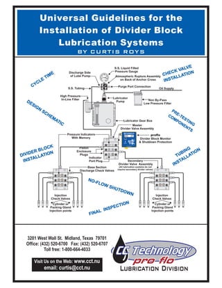
  • 1. Universal Guidelines for the Divider Block Lubrication Systems Installation of BY CURTIS ROYS Atmospheric Rupture Assembly on Back of Anchor Cross S.S. Tubing S.S. Liquid Filled Pressure Gauge Purge Port Connection Lubricator Gear Box Pressure Indicators With Memory Lubricator Pump Non By-Pass Low Pressure Filter Master Divider Valve Assembly proflo Divider Block Monitor & Shutdown Protection Oil Supply Indicator Port Plug Piston Enclosure Plugs Discharge Side of Lube Pump High Pressure In-Line Filter Injection Check Valves Cylinder or Packing Gland Injection points Cylinder or Packing Gland Injection points Injection Check Valves Secondary Divider Valve Assembly (All lubrication systems do not require secondary divider valves) Base Section Discharge Check Valves Set Mode T C C "PROTECTING COMPRESSORS WORLD WIDE" Midland, Texas 1-800-664-4033 C. C. Technology Inc. prO flOCLASS I, DIV II Groups A,B,C,D NRTL/C IrDA PORT AVG 20 R M o d e l - P F 1 US Copyright Registered 2001 500 1000 1500 2000 2500 3000II IIIIIIII IIIIIIIII IIIIIIIII IIII IIIIIIII IIIIIIIII IIIIIIIII II T C C CYCLE TIME DESIGN SCHEMATIC PRE-TESTING COMPONENTS PRE-TESTING COMPONENTS FINAL INSPECTION DIVIDER BLOCK INSTALLATION DIVIDER BLOCK INSTALLATION TUBING INSTALLATION TUBING INSTALLATION CHECK VALVE INSTALLATIONCHECK VALVE INSTALLATION NO-FLOW SHUTDOWN 3201 West Wall St. Midland, Texas 79701 Office: (432) 520-6700 Fax: (432) 520-6707 Toll free: 1-800-664-4033 Visit Us on the Web: www.cct.nu email: curtis@cct.nu
  • 2. INTRODUCTION: There are many procedures that should be observed when installing “Positive Displacement, Single Line Progressive Lubrication Systems”. This manual is intended for the person responsible for the installation of the divider block system. It contains procedures to maintain the system integrity and furnish the end user with a reliable divider block system. This Installation Guide addresses the complete divider block system installation from tubing installation to purging the system. The recommendations are specific to Single-Line Progressive Systems for compressor applications. Should the end user or person responsible for design of the divider block system have any questions concerning this manual or the operation and maintenance of the divider block system please feel free to contact CCTechnology at (432) 520-6700 , fax: (432) 520-6707 or email curtis@cct.nu. CC Technology Divider Block Installation Guide: Copyright (C) 2004 C CTechnologyInc. All rights reserved. Printed in the United States of America. No part of this publication may be reproduced in any part without written permission from the author. For information on lubrication products ortoobtain copiesofthis publicationcontactC CTechnology. Address: 3201WestWallSt.Midland,TX 79701 Phone:(432)520-6700 fax:(432)520-6700 E-mail:curtis@cct.nu WebSite:www.cct.nu
  • 3. GeneralGuidelinesforDividerBlock SystemInstallation: TestingComponentsforReliableOperation DesignSchematic DividerBlockCycleIndicatorandCycleTime Filters,LubeNo-FlowandShutdown Protection FinalInspection.....................................................................................page2 SchematicDesignExample: Position ofComponents: ComponentInstallation: MountingDividerBlocks: Critical Components: CheckValveInstallation: Tubing Preparation:............................................................................. Tubing Installation: Purging Air From the System: C C Technology Products................. ................................................................page3 ......................................................................page 4 .......................................................................page 4 DividerBlockInstallation: MasterDividerBlockInstallation: SecondaryDividerBlockInstallation: .....................................................................page 4&5 ...........................................................................page 6 .....................................................................page 7 page 8 ..............................................................................page 9-11 ..............................................................page 12 ....... ............................................Back Cover Purge and Pre-Lube Connection: Pressure Gauges: Atmospheric RuptureAssembly: In-line Filters: Lube No-Flow Shutdown: Check Valves: Base Plate Check Valves: Injection Check Valves: T CABLE OF ONTENTS Visit Us On the Internet www.cct.nu 1
  • 4. GENERAL GUIDELINES FOR DIVIDER BLOCK SYSTEMS A. TESTING COMPONENTS FOR RELIABLE OPERATION: Every component of the divider block system must be assembled and tested before shipping to the installation site. Every divider block system is designed for installation on a specific compressor. This ensures each component functions correctly and conforms to manufacturers specifications. Testing the assembled components before shipping eliminates possible on-site problems with the system after installation or during start-up. All components that are shipped unassembled should be accompanied with literature for specific assembly, testing and operating instructions. The lube system installer must always have a certified schematic of the divider block system designed by a qualified person. Each lube system design is based on various gas stream components, pressures and temperatures. When designing the divider block system the design engineer must consider not only gas stream components, but variables for lubrication rates due to materials used for the compressor rod, packing gland, cylinder and ring components. The schematic diagram should illustrate all tubing runs from each divider block to the injection point it is intended to serve. It should also include specific lube rates to individual injection points and all components needed to complete the installation of the system. (see figure "A" ) B. DESIGN SCHEMATIC: CC Technology Divider Block Installation Guide: C. CYCLE INDICATOR AND CYCLE TIME: D. FILTERS and LUBE NO-FLOW SHUTDOWN PROTECTION: E. FINAL INSPECTION: The lubrication system must include a device to indicate each cycle of the divider block system to set and monitor lube rates. To eliminate excessive wear the lube rates should be doubled for a minimum of 200 hours for new or rebuilt compressors. The lube system design must always include specifications for low and high pressure in-line filters A no-flow shutdown device must be installed on every divider block system, connected to the control panel and tested for operation, to ensure shutdown protection for the compressor in the event of lube system failure always re-check each component of the system There should never be any changes made to the divider block design system without approval of the engineer responsible for the system design. (see proflo monitor figure”A” The lube system design must include a suggested cycle time of the master divider block. The suggested cycle time allows the operator to set lube rates of the system for normal operation of the compressor. Lube rates should be doubled for break-in of the compressor components when starting up a new or freshly over hauled compressor. The compressor operator must adjust the lubricator pump until the divider block is cycling at the suggested cycle time to prevent premature failure of the compressor components. to avoid problems caused by contaminated lubricants, debris left in components during assembly or trash from open containers or reservoirs. . (see figure "A”) After installation of the divider block system is completed, the installer should including divider block sizes and tubing runs to ensure all lubrication points are being serviced by the correct divider block. 3201 West Wall St. Midland, TX 79701 (432) 520-6700 1-800-664-4033 fax: (432) 520-6707 2
  • 5. Pressurized Filtered Oil Atmospheric Rupture Assembly (Purple Disc) Torque to 36 Inch Pounds “DO NOT PLUG” 0-391040R Ariel Pressure Cross Assembly W/ S.S. Liquid Filled Pressure Gauge Purge Port & Atmospheric Rupture Assy. 0-391040L Ariel Pressure Cross Assembly W/ S.S. Liquid Filled Pressure Gauge Purge Port & Atmospheric Rupture Assy. Purge Port Connection Lubricator Gear Box Replace Oil & Check For Wear Every 12 Months (2) CCT 0-92377 3/8” Lubricator Pump Roller Rocker ALEMITE-L Pressure Test Every 12 Months 15.98 PPD 20.80 PPD 500 1000 1500 2000 2500 3000II IIIIIIII IIIIIIIII IIIIIIIII IIII IIIIIIII IIIIIIIII IIIIIIIII II 500 1000 1500 2000 2500 3000II IIIIIIII IIIIIIIII IIIIIIIII IIII IIIIIIII IIIIIIIII IIIIIIIII II T C CT C C 0-391042A CCT-0-509052 High Pressure 10 Micron In-line Filter Replace Element #EK9052 Every 12 Months 15.98 AVG 11.2 6 Pints Per Day LCD Should Display Sec. For Recommended Lube Rates @ Rated RPM Overhaul Break-in Cycle Time Seconds for 200 Hours RPM 1500 11.2 1400 12.0 1300 12.9 1200 14.0 1500 18.0 1400 19.2 1300 20.7 1200 22.5 RPM vs. Cycle Time Compressor Divider Block Cycle Time Sec. RPM Divider Block Cycle Time Sec. CCT-0-750014-1/4” Ultra Check Valve at Each Injection Point 0-T302500 Pressure Indicators 13.50” PKG- 2.40 PPD 13.50” CYL- 4.00 PPD 13.50” CYL- 4.00 PPD 18 T 30 T 13.50” PKG- 2.40 PPD 13.50” CYL- 4.00 PPD 13.50” CYL- 4.00 PPD 30 T 1-800-337-3412 ODESSA, TEXAS Set Mode T C C "PROTECTING COMPRESSORS WORLD WIDE" Midland, Texas 1-800-664-4033 C. C. Technology Inc. prO flOCLASS I, DIV II Groups A,B,C,D NRTL/C IrDA PORT PRO FLO R M o d e l - P F 1 US Copyright Registered 2001 1-800-337-3412 ODESSA, TEXAS Set Mode T C C "PROTECTING COMPRESSORS WORLD WIDE" Midland, Texas 1-800-664-4033 C. C. Technology Inc. prO flOCLASS I, DIV II Groups A,B,C,D NRTL/C IrDA PORT PRO FLO R M o d e l - P F 1 US Copyright Registered 2001 CCT-0-750014-1/4” Ultra Check Valve at Each Injection Point 0-T302500 Pressure Indicators 9.750” CYL- 6.38 PPD 6.375” PKG- 2.40 PPD 9 T 9.750” PKG- 2.40 PPD 6.375” CYL- 4.80 PPD 12 S 9 S 20.80 AVG 18.0 9 Pints Per Day LCD Should Display Sec. For Recommended Lube Rates @ Rated RPM Overhaul Break-in Cycle Time Seconds for 200 Hours SCHEMATIC DESIGN EXAMPLE Figure "A" RPM vs. Cycle Time 3201 West Wall St. Midland, TX 79701 (432) 520-6700 1-800-664-4033 fax: (432) 520-6707 Proflo Pf1 Divider Block Monitor and Lube No-Flow Shutdown Device CC Technology Divider Block Installation Guide: 3 Compressor
  • 6. 3201 West Wall St. Midland, TX 79701 (432) 520-6700 1-800-664-4033 fax: (432) 520-6707 CC Technology Divider Block Installation Guide: A. POSITION OF COMPONENTS: B. COMPONENT INSTALLATION: 1. Gearbox and Pump Installation: C. DIVIDER BLOCK INSTALLATION: Master Divider Block Installation: 1. Secondary Divider Block Installation: 2. D. MOUNTING DIVIDER BLOCKS: 1. Positioning of components on the compressor is essential Never install unnecessary conduit, piping, electrical connections or objects that will prevent the operator from having access to the lubricator pump and gearbox. to ensure the trouble free operation of any centralized lubrication system. If the correct components have been designed and selected, improper installation will make it difficult to access the system for purging air from the system or to replace components when preventive maintenance is performed. If the compressor does not have a specific mounting bracket for the lubricator reservoir, install the pump gearbox in an area on the compressor that is easy to access and not subjected to heavy traffic or debris. Easy access is necessary to enable the operator to adjust lubrication rates and to check the gearbox for correct oil levels. Install the master divider block (the first divider block downstream of the pump) as close to the pump as possible. This will allow the operator to adjust the lubricator pump while monitoring cycle time of the system to achieve correct lubrication rates. Install secondary divider blocks as close as possible to the injection points on the compressor cylinders and rod packing. This procedure eliminates long tubing runs from the divider block to the injection points and enables the operator to easily inspect the system for tubing leaks. Mount all divider blocks parallel to the floor. This allows complete purging of air from the system and makes it easier to install straight and plumb tubing runs. (See Figure "B" Below) 6 S 6 S 6 T 6 S 6 S 6 T INCORRECT MOUNTING CORRECT MOUNTING Divider Block Mounted Parallel to FloorDivider Block Not Mounted Parallel to Floor Figure "B” 4
  • 7. 3201 West Wall St. Midland, TX 79701 (432) 520-6700 1-800-664-4033 fax: (432) 520-6707 CC Technology Divider Block Installation Guide: D. Mounting Divider Blocks Continued: 2. 3. 4. 5 6. 7. CAUTION: 8. 9. 10. Avoid installing the divider blocks in locations that prevent easy access for preventative maintenance or replacement. The indicator port plugs on the front of the divider blocks should be easily accessed for trouble shooting the system for blockage and for ease of replacement. The divider blocks may be mounted directly to the compressor frame, if the surface can be drilled and tapped. When mounting the divider blocks directly to the cylinder, “ Mount all divider blocks on a flat surface wherever possible. Mounting to an uneven surface may cause distortion in the piston bores and create premature wear or failure. Use properly sized bolts for mounting the divider blocks to the compressor frame. Use divider block mounting brackets in areas that require the divider block to be raised from the mounting surface to enable reliable tubing installation. CC Tech has several styles of mounting brackets to ensure correct mounting of the divider blocks When using a mounting plate that must be welded in place, “ Heat or sparking generated during welding will permanently damage the divider blocks. Install all divider block assemblies in an area on the compressor to avoid damage from debris or dropped objects. Install the tubing on the compressor frame away from common areas that must be accessed for maintenance and out of areas commonly used for stepping or where there is the possibility of damage from debris or dropped objects. Keep all multiple tubing runs from secondary divider blocks as short as possible to reduce total lubricant volume held in the lines to the injection points. DO NOT” use long drill bits that can penetrate through the inside wall of the compressor cylinder. NEVER” weld on a mounting plate with the divider block installed. 5
  • 8. E. CRITICALCOMPONENTS: 1. Purge and Pre-Lube Connection: 2. Pressure Gauges: Atmospheric RuptureAssembly: 4. In-line Filters: Always install a purge port connection on the discharge side of the pump The purge port connection must incorporate a check valve Proper purging of air from the divider block system before compressor start- up is critical for reliable and trouble free operation of the system. It is absolutely necessary to install pressure gauges on all divider block systems Atmospheric rupture assemblies must be installed on every divider block system Every system must have in-line filters with a minimum of 25 micron filtration to prevent contamination and failure of the lube pump and divider blocks. to allow purging air from the tubing lines before compressor startup or after any maintenance is performed on the divider block system.(see figure “ ”) to keep oil from blowing out of the system and allowing air to enter the system when removing the purge gun. If no check valve is in place air will enter the system when removing the purge gun. Trapped air can cause phantom shutdowns of the compressor and has the same indications as divider block failure or trash in the system. (See page 12) to enable the operator to monitor system pressure and operation of the divider block system. (see figure “ ”). to release pressure if blockage occurs in the system. The relieving of oil flow to atmosphere enables the lube no- flow to shutdown the compressor. The compressor will never shutdown if an atmospheric assembly is not installed or if the atmospheric rupture assembly has been plugged. (see figure " ”) It is recommended to install both a low pressure pre-filter before the pump and high pressure in-line filter downstream of the lube pump. Install all in-line filters in an area that can easily be accessed for filter changes or cleaning at recommended maintenance intervals. (see figure " ”) 3. C-1 C-2 C-3 C-4 3201 West Wall St. Midland, TX 79701 (432) 520-6700 1-800-664-4033 fax: (432) 520-6707 CC Technology Divider Block Installation Guide: 500 1000 1500 2000 2500 3000II IIIIIIII IIIIIIIII IIIIIIIII IIII IIIIIIII IIIIIIIII IIIIIIIII II 500 1000 1500 2000 2500 3000II IIIIIIII IIIIIIIII IIIIIIIII IIII IIIIIIII IIIIIIIII IIIIIIIII II T C CT C C 0-391042A ( ) CCT-0-509052 High Pressure In-line Filter 10 Micron C-4 ( ) Purge Port Connection C-1 ( ) Atmospheric Rupture Assembly C-3 ( ) Pressure Gauge C-2 High Speed Separable Compressor Model 55 Type Lubricator Figure "B" 1725 RPM -1HP Model # 3546-230-460 TEFC ELECTRIC MOTOR B-118 ( ) 1211-B-118 Low pressure In-Line Filter C-4 ( ) 0-2Z763-9 Filter Primer C-4 lincoln modular lube 8 : 1 C C Technology 21.5:1 500 1000 1500 2000 2500 3000II IIIIIIII IIIIIIIII IIIIIIIII II T C C ( ) Atmospheric Rupture Assembly on Back of PCA C-3 Slow or High Speed Compressor with Electric Driven HVLP Lube Pump and Gear Box To Master Divider Block From Oil Supply ( ) Purge Port Connection C-1 ( ) Pressure Gauge C-2 6
  • 9. E. CRITICALCOMPONENTS CONTINUED: 5. Lube No-Flow Shutdown: F. Check Valves: 1. Base Plate Check Valves: The lube no-flow device is the only shutdown protection for the compressor if the pump fails or blockage occurs in the system. Operating pressure of the check valve must be appropriate for working pressure of the system. to increase the dependability and fluid movement of the divider block piston. Base plate check valves prevent introduction of gas or air into the hydraulic circuit of the divider block if the injection check valve should fail. “DO NOT” operate any divider block system without a lube no-flow shutdown device. All divider block systems must have a check valve installed at each injection point. Install base plate check valves (termed Reverse Checks) on each working outlet of the base plate 2. Injection Check Valves: Check valves must be installed on all lubrication points For reliable operation “DO NOT” install the injection check valves in a vertical position. as close as possible to the injection point. C Vertical installation can allow the introduction of hot, contaminated gas into the check valve every time the valve opens to inject oil into the lubrication point. The gas migrating into the check valve as it opens and closes can also cause possible coking of oil on the ball and seat of the check valve causing premature failure. (See figure "D”) heck valves should be installed in a manner as to permit a minimum of 1” of oil head above the check valve. The 1" of oil head will allow a liquid seal in the check valve and keep the heated gas and debris separated from the check valve seat for increased reliability. CC Technology Divider Block Installation Guide: Cylinder 1” MINIMUM LIQUID SEAL RECOMMENDED Check Valve 1” Cylinder Check Valve NOT RECOMMENDED RECOMMENDED Cylinder Check Valve Cylinder 1” MINIMUM LIQUID SEAL RECOMMENDED Check Valve 1” Check Valve Installation Using the CC Tech Oil Head Adapter 1” Cylinder Check Valve Oil Head to Protect Check Valve Sealing Surface Oil Figure "D” 3201 West Wall St. Midland, TX 79701 (432) 520-6700 1-800-664-4033 fax: (432) 520-6707 7
  • 10. A. TUBING PREPARATION 1. Cleaning Tubing and Piping: 2. Tubing Flushing Procedure: 3. Cutting the Tubing: When installing the divider block system, . The initial startup of the divider block system is the most critical time. Any debris or contamination that is present in the hydraulic system will cause immediate or premature failure of the divider block components. If debris is present in the system during initial startup it will be carried through the hydraulic circuit and deposited in the divider block pistons, check valves and rod packing or directly into the compressor cylinder. If debris in the hydraulic system does not cause immediate damage to the system components, the existing particles can cause premature failure of the system due to degradation of the components caused by wear. 1. If the ends of the tubing have been left open to the environment all tubing should be flushed with high-pressure water to remove any debris that could be present from transportation to the job site or during storage . 2.After loosening the debris with high pressure water washing, insert an air gun in the end of the tubing and blow out the loose debris.Always use clean filtered air. (see figure "E") If the tubing is to be stored for any length of time, the ends should be capped to prevent contamination. 1. All tubing should be cut with industry standard tubing cutters such as the one in figure “F” designed to be used with stainless steel tubing. The cutting wheel must be sharp to obtain a smooth square cut. 2. After cutting the inside and outside of the tube end must be de-burred and cleaned to prevent metal particles from entering the lubrication system damaging the lube pump, divider blocks, or compressor components. It is recommended to use a de-burring tool such the one in figure "G”. all tubing and piping must be thoroughly cleaned to assure reliability of the lubrication system For reliable operation of the divider block system it is extremely important to avoid any introduction of foreign debris in the hydraulic circuit or tubing lines. 3201 West Wall St. Midland, TX 79701 (432) 520-6700 1-800-664-4033 fax: (432) 520-6707 Figure "G”Figure "E” CC Technology Divider Block Installation Guide: 8 Figure "F”
  • 11. B. TUBING INSTALLATION: 1. Routing of Tubing Bends: 2.Avoid Excessive Strain on Joints: The divider block system schematic designates the points on the compressor to be lubricated and the exact divider block that should be connected to each injection point.The schematic must be followed as per the drawing but it does not identify the paths to follow due to differences in compressor frames and installations. The basic rule to remember when installing tubing is to keep all lines as short as possible with a minimum number of bends. By reducing the number of bends you reduce the pressure drop in the hydraulic system. The installer should remember the operator must maintain the compressor and the tubing installation should not interfere with everyday tasks of preventative maintenance performed on the compressor. The most logical path and related guidelines are demonstrated in the illustrations on the following pages. A. Short tubing runs should incorporate a bend to allow removal of the tubing to compensate for expansion and contraction caused movement generated in a pressurized system. (see figure "H") B. - Use a “U" bend in long lines to allow for expansion. Strained joints in tubing bends will eventually leak. (see figure "H") Routing of tubing is the most difficult but most significant of the installation considerations. Proper routing involves installing tubing from one point to another through the most logical path. Avoid straight short tubing runs. A strained joint will eventually leak. Allow for expansion and contraction INCORRECT ROUTING INCORRECT ROUTING CORRECT ROUTING CORRECT ROUTING Figure "H” INCORRECT ROUTINGCORRECT ROUTING 3201 West Wall St. Midland, TX 79701 (432) 520-6700 1-800-664-4033 fax: (432) 520-6707 CC Technology Divider Block Installation Guide: 9
  • 12. B. TUBING INSTALLATION CONTINUED: 3. Install tubing around obstructions without excessive 90 bends: 4. Do not install tubing on walkways or in areas where it could present a safety hazard. 5. Keep tubing lines away from any components that require maintenance: 6. Follow the shape of the object or surface with tubing bends: o Pressure drop due to one 90 bend is greater than two 5 o bends. (see figure "I") 1.Do not install tubing where it could be damaged by operators performing everyday preventative maintenance. Tubing lines that are installed over the top of, or next to components that must be accessed for maintenance will be moved or bent to enable the operator to access the component. Bending the tubing by force to access components could cause leaks or failure of the tubing connections.(see figure "J") 1.Install tubing to conform to surfaces or objects as close as possible. Installation of tubing lines that stand out away from objects are easily damaged and create possible safety hazards.(see figure "K") Figure "I” Figure "J” INCORRECT ROUTINGCORRECT ROUTING INCORRECT ROUTINGCORRECT ROUTING Figure "K” INCORRECT ROUTINGCORRECT ROUTING 3201 West Wall St. Midland, TX 79701 (432) 520-6700 1-800-664-4033 fax: (432) 520-6707 CC Technology Divider Block Installation Guide: 10
  • 13. B. TUBING INSTALLATION CONTINUED: 7. TubingAppearance: 8. Securing and Supporting Tubing: Tubing lines should have a clean and orderly appearance to allow the operator to easily troubleshoot the system for leaks and perform repairs. (see figure "L") Multiple tubing lines should not be left suspended in mid-air without securing them together using tubing clips with back plates for support. Tubing clips are used to secure multiple tubing lines together eliminating vibration against each other. Tubing left unsupported could eventually leak due to vibration. Vibration could cause the fitting to loosen or create fatigue in the tubing which will lead to the tubing splitting and leaking. Tubing can be clamped individually or in sets from 2 to 12 lines. o ensure reliable trouble free service of the divider block system and protect the compressor from possible premature wear due to insufficient lubrication. (see figure "M") To ensure orderly appearance of the tubing and reliability of the divider block system all tubing lines must supported and secured after installation. Use sufficient tubing clips to properly support and secure the tubing t Figure "L” INCORRECT ROUTING No Tubing Clips CORRECT ROUTING with Proper Tubing Clips Figure "M” VERTICAL TUBING SUPPORT With Tubing Clips and Back Plates HORIZONTAL CLAMPING Directly to the Compressor Frame 3201 West Wall St. Midland, TX 79701 (432) 520-6700 1-800-664-4033 fax: (432) 520-6707 CC Technology Divider Block Installation Guide: 11
  • 14. C. Purging Air from the System and pre-lubing the components: Divider block systems operate correctly only when all tubing lines and components are completely filled with oil to eliminate air in the system. The operator should always pre-lube the divider block system and components before the compressor is started. 1. After the lubrication system is installed, it is necessary to purge air from all components, (tubing, divider blocks, check valves) and fill the entire system with oil that will be used to lubricate the compressor components during normal operation. Model # 382510-3 Lubrication System Purge Gun The divider block system should always be purged of air and pre-lubed if any components are removed or loosened after the initial installation and start-up of the compressor. Although divider block systems can eventually self purge, this severely delays purging air from the divider blocks, tubing and filters and can result in erratic operation of the system and cause phantom shutdowns and premature wear or failure of compressor components. Purge Gun Pump in Vertical Position (5) Purge Port with Check Vakve 1/4” S.S. Tubing (6) Discharge Side of Lube Pump Tubing Connection (4) Secondary Divider Valve Inlet (2 & 3) Tubing Connections Cylinder or Packing Gland Injection Points (1) Tubing Connection Master Divider Valve Inlet Follow this procedure after installation of the divider block system is completed or when any components are replaced, removed or any maintenance is performed on the system. Step 1: Step 2: Step 3: Step 4: Step 5: Step 6: Step 7: Step 8: The lubrication system is now ready to operate. After installation of the lube system and before compressor start-up loosen all tubing connections at the inlet of the master divider valve (1), . If there are secondary divider valves (4) loosen tubing connections at the inlet of the secondary divider valves . If a purge port (5) is available at the pump head connect the purge gun. If no purge port is available remove the tubing from the discharge side of the pump (6) and connect the purge gun to the tubing. Pump clean oil common to the system into the tubing line until there are no air bubbles observed flowing from the tubing connection at the inlet of the master divider valve. Always hold purge gun in a vertical position to eliminate pumping air into the system. Tighten the tubing connection at the inlet of the master divider valve while oil is still flowing. Continue to operate the purge gun until no air bubbles are observed flowing from the tubing connection at the inlet of the secondary divider valve. Tighten the tubing connection at the inlet of the secondary divider valve while oil is still flowing. Continue to operate the purge gun until there are no air bubbles observed flowing from the tubing connections at the cylinder or packing gland injection points. Tighten the tubing connections at the cylinder and packing gland injection points while oil is still flowing. cylinder injection points (2) and packing gland injection points (3) 5001000 1500 2000 25003000 T C C 3201 West Wall St. Midland, TX 79701 (432) 520-6700 1-800-664-4033 fax: (432) 520-6707 (2 & 3) Tubing Connections Cylinder or Packing Gland Injection Points CC Technology Divider Block Installation Guide: 12