2. larger sample sizes and reach higher redshifts, but they suffer
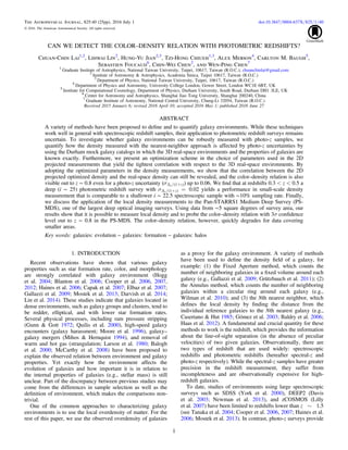
from poorer redshift resolution. Figures 1–3 show how the
photo-z uncertainties distort the real galaxy environment from
different viewpoints. The large-scale structures are clearly
revealed in the case without photo-z error but become less
prominent as the photo-z error increases. Despite this problem,
there have been some attempts to measure the galaxy
environment for various studies using photo-z samples (Capak
et al. 2007; Quadri et al. 2012; Scoville et al. 2013; Chiang
et al. 2014; Lin et al. 2016). Several works have provided
viable methods that can be used to recover the density fields of
galaxies from photo-z samples (Etherington & Thomas 2015;
Lin et al. 2016; Malavasi et al. 2016). Moreover, Arnalte-Mur
et al. (2009) and Schlagenhaufer et al. (2012) both demon-
strated that the two-point correlation function of galaxies can
also be successfully recovered from photometric samples, and
they also discussed the influence of photo-z errors on their
measurements.
Several ongoing large sky surveys such as the Panoramic
Survey Telescope and Rapid Response System (Pan-STARRS:
Onaka et al. 2008; Kaiser et al. 2010), Dark Energy Survey (The
Dark Energy Survey Collaboration 2005; Albrecht et al. 2006),
Hyper Suprime-Cam Survey (Miyazaki et al. 2012), and the
upcoming Large Synoptic Survey Telescope (LSST Science
Collaboration et al. 2009) will yield large galaxy samples with
photometric redshift measurements, so it is important to under-
stand the potential and limitations of the photo-z method in the
studies of galaxy evolution, especially the environmental effects.
Can we use photo-z samples to measure environment reliably?
What are the systematics in the environment measurement
between spectral-z samples and photo-z samples? What is the
optimal choice for density measurement that can reliably recover
the underlying environments? These are the questions that we
aim to answer. In particular, we focus on the measurement of the
density field of a galaxy. We first study the difference between
3D real-space density and 2D projected density measurements by
using mock galaxy catalogs. We adopt Spearman’s rank
correlation coefficient (Spearman 1904), rs, as a measure of the
correlation between the 2D and the 3D real-space density. The
optimized parameters for the density measurement are obtained
by maximizing rs. We then use the results of optimized density
measurements to show the dependence of galaxy properties on
environments from the mock catalog. Finally, we apply our
optimized scheme to the Pan-STARRS1 data and compare the
results with the measurements by Cooper et al. (2006), who use
the DEEP2 spectroscopic sample in the same field.
This paper is structured as follows. In Sections 2.1 and 2.2
we describe the simulation and observational data used in our
Figure 1. Spatial distribution of mock galaxies projected onto the plane of the sky with redshifts perturbed corresponding to different photo-z errors: 0.00,
( )+ z0.02 1 , ( )+ z0.04 1 , and ( )+ z0.06 1 at < <z0.3 0.35photo .
2
The Astrophysical Journal, 825:40 (25pp), 2016 July 1 Lai et al.
3. study. The environment measurements used in this study are
introduced in Section 3. In Section 4 we compare the 3D real-
space density with the 2D projected environment, and
demonstrate how to optimize the choice of Nth nearest
neighbor to improve the 2D projected density measurement.
In Section 5 we show the relation between galaxy environment
and galaxy properties in the mock galaxy catalog to verify
whether or not our optimized scheme is applicable. We discuss
several possible factors that might limit our optimized scheme
and apply it to observations in Section 6. Finally we summarize
our results in Section 7. In this paper, we adopt the following
cosmological parameters: H0 = 100h km s−1
Mpc−1
, h = 0.73,
W = 0.250 , and W =L 0.75.
2. DATA
2.1. Simulation Data
In this work, we use a theoretical mock galaxy catalog to
understand the systematics in the local density estimates. The
advantage of using a mock galaxy catalog compared to real
spectroscopic survey data is that the real-space density can be
directly measured and compared with the projected density.
Moreover, the mock sample does not suffer from the
incompleteness that often affects real observations. On the
other hand, one needs to be cautious when interpreting the
results since the properties of galaxies in the simulation may
not be a perfect representation of the real universe.
The mock galaxy catalog used in this work is built based on the
Millennium simulation with =N 21603 in a box with
volume = 5003
h−3
Mpc3
from redshift z = 127 to the present
day at z = 0 by adopting the following cosmological parameters: a
baryon matter density Ωb = 0.045, a total matter density
Ω0 = 0.25, a dark energy density ΩΛ = 0.75, and a Hubble
constant H0 = 100h km s−1
Mpc−1
where h = 0.73. These cos-
mological parameters match the first-year results of the Wilkinson
Microwave Anisotropy Probe (Spergel et al. 2003). Galaxies are
put into halos using the GALFORM semi-analytical model (Cole
et al. 2000), which takes into account various galaxy formation
processes including gas accretion and cooling, star formation in
galactic disks, and galaxy mergers. The mock catalog adopts the
model of Lagos et al. (2012), which takes advantage of the
extension to the treatment of star formation introduced into
GALFORM in Lagos et al. (2011) to populate galaxies, and is
then assembled into a lightcone (Merson et al. 2013). Further
detailed information is given in Cole et al. (2000), Springel et al.
(2005), Bower et al. (2006), Lagos et al. (2011, 2012), and
Merson et al. (2013).
Figure 2. Spatial distribution of mock galaxies seen in one line-of-sight projection and redshift. A 0°.05 interval in decl. is used when projecting galaxies onto the
plane. The redshifts of galaxies are perturbed according to different photo-z errors: 0.00, ( )+ z0.02 1 , ( )+ z0.04 1 , and ( )+ z0.06 1 . The red rectangle indicates the
redshift range < <z0.3 0.35photo used in Figure 1.
3
The Astrophysical Journal, 825:40 (25pp), 2016 July 1 Lai et al.
4. We constructed two types of mock catalogs that mimic the
observed spectral-z and photo-z catalogs. The mock spectral-z
catalog can be obtained from primitive simulation data, which
store the intrinsic line-of-sight positions of galaxies. To
generate mock photo-z catalogs, we perturb the position of
galaxies along the line-of-sight direction by making a random
shift that follows a Gaussian distribution with a standard
deviation that matches the photo-z error in each case, in order
to simulate cases with observed redshift uncertainties. The new
redshift obtained can be viewed as the “observed redshift,” and
used to compute the local density. Although the photometric
redshift model adopted here is oversimplified because it does
not take into account the effect of catastrophic redshift failures,
this simplistic model allows us to understand the effect of
redshift dispersion. Later, in Section 5.4, we consider more
realistic situations in which the outlier effect is included. In this
study we consider several photo-z cases with uncertainties of
( )sD +z1z
= 0.00, 0.02, 0.04, and 0.06. We restrict our
environment study to the redshift range 0.3 < z < 0.5 for
most of our analysis. A central area of the catalogs of ∼16
square degrees is selected for our studies, containing
∼1,900,000 galaxies with <i 25.8. It is worth noting that the
redshift that we use for computing the 3D overdensity with the
Millennium mock spectroscopic catalogs refers to the intrinsic
redshift of galaxies, which does not include the effect from
peculiar velocity. Therefore, the results shown for the spectro-
scopic redshift sample may be too optimistic. However, since
our main focus is to understand the performance of density
recovery in the case of photometric errors, this mock spectro-
scopic catalog does provide a “real” answer for the 3D density.
2.2. Observation Data
2.2.1. Spectroscopic Observation
The DEEP2 Galaxy Survey (Davis et al. 2003; Newman
et al. 2013) was designed to study the galaxy population and
large-scale structure at z ∼ 1. It uses the Keck II telescopes with
the DEIMOS spectrograph (Faber et al. 2003), covers ∼3.5
square degrees of the sky with measured spectra, and has targeted
∼60,000 galaxies down to a limiting magnitude of RAB < 24.1.
About ∼60% of the galaxies are sampled over the redshift
interval 0.2 < z < 1.4. The overall redshift success rate is about
∼70%. DEEP2 comprises four widely separated fields. One of
the DEEP2 fields, the Extended Groth Strip (EGS), is enclosed
by the Pan-STARRS1 Medium Deep Survey Field (MD07). In
this study we match the DEEP2 spectroscopic redshift catalog to
the Pan-STARRS1 MD07 catalog. For galaxies that are common
to the two catalogs, we compare the local density measurements
computed using the DEEP2 spectral-z and Pan-STARRS1 photo-
z respectively (see Section 6).
Figure 3. Spatial distribution of mock galaxies seen in one line-of-sight projection and redshift. A 0°.05 interval in R.A. is used when projecting galaxies onto the
plane. The redshifts of galaxies are perturbed according to different photo-z errors: 0.00, ( )+ z0.02 1 , ( )+ z0.04 1 , and ( )+ z0.06 1 . The red rectangle indicates the
redshift range < <z0.3 0.35photo used in Figure 1.
4
The Astrophysical Journal, 825:40 (25pp), 2016 July 1 Lai et al.
5. 2.2.2. Photometric Observation
Pan-STARRS1 (hereafter PS1) is a 1.8 m telescope equipped
with a CCD digital camera with 1.4 billion pixels and 3° field
of view, located on the summit of Haleakala on Maui, Hawaii
(Onaka et al. 2008; Kaiser et al. 2010). The PS1 observations
are obtained in a set of five broadband filters, which we have
designated as g r i z, , ,p p p p1 1 1 1, and yp1. There are two major
components of the PS1 survey, which started observations in
2010: the 3π survey and the Medium Deep Survey (MDS),
which comprises ten fields spread across the sky. One of the
MDS fields, namely MD07, is chosen for this study because it
overlaps with the EGS field, which has the spectroscopic data
from the DEEP2 survey, and enables a direct comparison with
the environment measurements using the DEEP2 spectral-z
sample (Cooper et al. 2006). Photo-z redshifts in MD07 are
computed by running the EAZY code (Brammer et al. 2008) on
PS1 five-band photometry plus the u*
-band data taken by
Eugene Magnier et al. with CFHT MEGACAM as part of the
PS1 efforts. Comparisons against the DEEP2 spectroscopic
redshifts (Newman et al. 2013) show that the PS1 photo-z
reaches an uncertainty of 0.05 with an outlier rate of 7% down
to <r 24.1p1 . More details on the data processing and photo-z
characteristics in the PS1 MD07 sample are given in Lin et al.
(2014) and S. Foucaud et al. (2016, in preparation).
3. MEASUREMENTS OF GALAXY ENVIRONMENT
In this study, we adopt the Nth nearest-neighbor method to
quantify galaxy environment. This method defines the local
density of each galaxy using the distance to the Nth nearest-
neighbor galaxy. In other words, whether the galaxy is located
in an overdense or underdense environment depends on how
far it is from its Nth nearest galaxy. In simulations, the
cosmological redshift reflects the “real” distance along the line
of sight, enabling the environment measurement to be
evaluated by using the 3D Nth nearest-neighbor method. On
the other hand, observationally, the local density is often
estimated by using a projected method because the measured
redshift is a combination of both the cosmological distance and
the peculiar velocity.
Here we define two sets of galaxy samples: the primary and
the secondary. The primary sample contains galaxies brighter
than a particular magnitude (mi
p
), and is used when presenting
the results. The secondary sample refers to galaxies used in the
search for neighbors, and is restricted to those galaxies that are
brighter than a particular magnitude (mi
s
). The limiting
magnitude of the secondary sample is particularly important
because it sets the galaxy number densities in the calculation of
density field. Figure 4 shows the median distances to the 3D
Nth nearest neighbor with various choices of mi
s
. The colored
areas show the range between the minimum and maximum
distances to the 3D Nth nearest neighbor. There are several
parameters that should be considered in the Nth nearest-
neighbor method: (1) the choice of the Nth neighbor, which
represents the scale of the environment, (2) the magnitude limit
of the primary sample (mi
p
), (3) the magnitude limit of the
secondary sample (mi
s
), and (4) the velocity window (Vcut) that
defines the redshift boundaries of the neighbors considered in
the 2D projected method. These parameters should be adjusted
according to different science goals and galaxy samples. One of
the goals of this work is to provide an empirical framework that
determines these parameters by calculating galaxy densities
with different combinations of parameters in order to under-
stand their influence.
3.1. 2D Projected Nth Nearest-neighbor Galaxy Environment
In the 2D projected method, the local density of each galaxy
is computed as the surface density averaged over the area
enclosed by the Nth closest galaxy within the velocity interval
Vcut:
( )
p
S =
+n
r
1
, 1n
n
2
where n is the Nth closest galaxy for each reference galaxy and
rn is the distance from the reference galaxy to the Nth closest
galaxy on a 2D surface. There is no simple way to determine
Figure 4. The median Nth nearest-neighbor distance as a function of N3D for various choices of the magnitude limit of the secondary sample (mi
s
). The areas shaded in
different colors show the range between the minimum and maximum Nth nearest-neighbor distances.
5
The Astrophysical Journal, 825:40 (25pp), 2016 July 1 Lai et al.
6. the choice of velocity window Vcut in the 2D nearest-neighbor
method. In principle, it is not meaningful to adopt a Vcut that is
too small compared to the redshift uncertainty of the data.
Conversely, adopting a large velocity cut enlarges the
projection effect, which leads to greater errors in the density
measurement. For instance, two galaxies that are close in the
projected plane may actually be widely separated in the third
dimension, and vice versa (Muldrew et al. 2012). Previous
studies have utilized the velocity interval Vcut of a value close to
the distance uncertainties in the line-of-sight direction, because
they found that the density estimate does not vary significantly
when changing Vcut around this value. We will further test this
approach using the mock catalog in Section 4.1.
3.2. 3D Nth Nearest-neighbor Galaxy Environment
The galaxy environment defined by the 3D Nth nearest-
neighbor method is similar to that defined by the 2D projected
Nth nearest-neighbor method except that the projected circular
area is replaced by the enclosed spherical volume. The volume
density of galaxies is evaluated using the 3D Nth nearest-
neighbor method as
( )
( )r
p
=
+n
r
1
4 3
, 2n
n
3
where n is the Nth closest galaxy of each reference galaxy and
rn is the distance from the reference galaxy to the Nth closest
galaxy in the three-dimensional space. We compute the real-
space density using the 3D Nth nearest-neighbor method of the
simulation where information about the three-dimensional
positions of galaxies is known. We treat the 3D density as
the “true” density to be compared with the 2D density to
quantify how well the real-space density can be recovered by
the 2D projected density under various conditions. We note that
in practice the 3D density is rarely used, even in a spectro-
scopic redshift sample, because the observed “redshift”
includes contributions from both the Hubble flow and the
peculiar velocity of galaxies, which it is not possible to
differentiate observationally.
Finally, in order to contrast the most dense environments
with the least dense environments, we convert the initial
primordial density into an overdensity. The overdensity is
conventionally defined as the initial primordial density divided
by the median density as follows:
( )d+ =
D
D
1 , 3n
i
Mdn
where Di is the measured density of a galaxy (i.e.,
{ }rÎ SD ,i n n ), and DMdn is the median density computed by
counting galaxies within a bin of Δz = 0.04. The term d+1 n is
the so-called overdensity, and dn can be dn
3D
or dn
2D
, depending
on whether Di = ρn or Sn.
4. QUANTIFYING DIFFERENCES BETWEEN
ENVIRONMENT MEASUREMENTS
In this section, we compare the 2D projected density
obtained under various conditions to the 3D real-space density.
To quantify their differences, we adopt Spearman’s rank
correlation coefficient, rs, which is commonly used to measure
the strength of a relationship between two ranked variables
(Spearman 1904; Curran 2014). Spearman’s rank correlation
coefficient is defined as
( )
( )= -
å
-
r
d
s s
1
6
1
, 4s
i
2
2
where di is the difference between the ranks of the two
variables and s is the sample size. A coefficient rs = 0
corresponds to no correlation between two variables, while
rs = 1 (−1) corresponds to a perfect-positive (perfect-negative)
correlation. In our analysis, we first measure the 2D projected
density Sn as well as the 3D real-space density rn for each
galaxy, and then convert all the density measurements into an
overdensity as defined in the previous section. After ranking
the 3D real-space overdensity and 2D projected overdensity,
we compute the difference di between the ranks of the two
overdensities, and then use Equation (4) to calculate Spear-
man’s rank correlation coefficient rs.
Figure 5 is an example showing the correlation between the
3D and 2D measurements using N2D = 6, 30, 60, and 90, and
how the rs coefficient changes with different choices of N2D.
4.1. 3D Galaxy Environment Versus 2D Projected Galaxy
Environment with Different Parameters
We first probe the effect of the velocity interval Vcut on the
2D projected density measurement. We restrict the sample to
<m 25i
p
and <m 25i
s
when calculating 2D projected over-
density, d+1 6
2D
, and 3D real-space overdensity, d+1 6
3D
.
Figure 6 shows the scatter plots of the 2D projected overdensity
versus the real-space overdensity on a log scale using the sixth-
nearest neighbor. Here we consider the following four different
choices of Vcut in the 2D projected measurement for a galaxy
sample with photo-z error = 0.04(1 + z): ±0.005(1 + z),
( ) + z0.02 1 , ( ) + z0.04 1 , and ( ) + z0.06 1 . It can be
seen that the difference in rs among the four cases of Vcut is not
significant when the size of velocity interval is close to the
photo-z error. For example, rs of 0.434 is obtained in the case
of Vcut = ±0.02(1 + z) (upper-right panel of Figure 6), while
the value of rs increases to 0.473 in the case of Vcut = ±0.06(1
+ z) (lower-right panel of Figure 6). The difference in rs is
small (∼0.039) between these two cases even though Vcut
differs by a factor of 3, which confirms the finding in previous
studies that the 2D projected measurement is not sensitive to
Vcut when Vcut is comparable to the photo-z uncertainty (Gallazzi
et al. 2009; Muldrew et al. 2012). We further repeat similar
exercises using samples with a larger redshift uncertainty up to
( )+ z0.08 1 and at higher redshifts (0.6 < z < 0.8), and we find
that this conclusion still holds. Therefore throughout this work
we set Vcut to be the typical photo-z uncertainty of the galaxy
sample.
Next we consider the effect of the secondary magnitude limit
employed on the galaxy sample when searching for neighbors.
A brighter (fainter) mi
s
probes a larger (smaller) scale of
environment for a fixed Nth nearest neighbor. It is therefore
expected that the correlation between the 2D projected and 3D
real-space environments could depend on the choice of mi
s
.
Again we select the sample with photo-z error = 0.02(1 + z)
and set Vcut = ±0.02(1 + z) for the reason given above.
Figure 7 shows the scatter plots of the 2D projected overdensity
versus real-space overdensity using the sixth-nearest neighbor,
6
The Astrophysical Journal, 825:40 (25pp), 2016 July 1 Lai et al.
7. and both 2D and 3D environments are measured using
<m 21i
s
, <m 23i
s
, and <m 25i
s
. As can be seen, the largest
rs is obtained when mi
s
in the 2D measurement is equal to mi
s
in
the 3D measurement. Furthermore, for identical mi
s
used in the
2D and 3D measurements, the environments measured by using
fainter mi
s
(and hence smaller scales) have better correlation
than those measured using a brighter mi
s
. This is consistent with
the results from Shattow et al. (2013), which also shows that
for samples with photo-z error, the 2D projected environments
have a weaker correlation with 3D real-space environments on
larger scales.
Finally, Figure 8 shows the 2D versus 3D scatter plots in the
density measurement to understand how the galaxy environ-
ment is affected by the photo-z errors. Here we consider
<m 25i
p
and <m 25i
s
, and vary the photo-z error from 0,
( )+ z0.02 1 , ( )+ z0.04 1 , to ( )+ z0.06 1 . Vcut is correspond-
ingly set to be ( ) + z0.001 1 , ( ) + z0.02 1 , ( ) + z0.04 1 ,
and ( ) + z0.06 1 respectively. It is worth noting that even in
the perfect situation where the redshift error is zero, the
correlation is still not perfect owing to the projection effect.
The correlation between 3D real-space and 2D projected
environments becomes gradually worse when the photo-z error
increases. However, there still exists some correlation espe-
cially for galaxies located in high-density regions, while the
environment in lower and intermediate densities is less
distinguishable. This is consistent with the result from Capak
et al. (2007), who also showed that the galaxy environment is
difficult to measure for galaxies located in regions of low
density when a redshift error is present.
4.2. Optimizing 2D Environment Parameters
So far we have compared 3D real-space environments with
various 2D projected environments to show their correlation
and we have adopted rs to quantify the goodness of the
correlation. We now expand this to construct an optimization
scheme to determine the value of N2D that gives the best
correlation (largest rs) between the 2D and 3D environments.
Figure 9 shows rs calculated by fitting 2D projected and 3D
real-space environments with various choices of N2D and N3D.
Figure 5. Scatter plot of the 3D real-space overdensity, d+1 6
3D
, vs. 2D projected overdensity: d+1 6
2D
(upper-left panel), d+1 30
2D
(upper-right panel), d+1 60
2D
(lower-left panel), and d+1 90
2D
(lower-right panel) on a log scale. The numbers in the bottom left of each panel indicate the rs coefficient. The black dashed–dotted
lines represent the best fit to the data points, the red dashed–dotted lines represent the one-to-one relation, and the contours show the regions of constant galaxy
number.
7
The Astrophysical Journal, 825:40 (25pp), 2016 July 1 Lai et al.
8. The red, green, blue, cyan, and magenta dots are for the cases
where the 2D projected environments are calculated using
N2D = 6, 30, 60, 90, and N3D respectively. We also mark the
four cases of Figure 5, rs = 0.425, 0.455, 0.503, and 0.549
respectively, to demonstrate how rs varies with different
choices of N2D. In the following analysis, we show only the
optimized choice of N2D corresponding to the case that yields
the largest rs, as a function of N3D.
Figure 10 shows the largest rs (upper panel) and corresp-
onding choice of N2D (lower panel) that yields the best
correlation between 2D projected and 3D real-space environ-
ments for different choices of N2D, as a function of N3D from
mock galaxy catalogs. The red, green, blue, and cyan dots are
for samples with different photo-z errors: 0.00, ( )+ z0.02 1 ,
( )+ z0.04 1 , ( )+ z0.06 1 respectively. As expected, the
densities are relatively easier to recover for samples with lower
photo-z errors than for those with higher photo-z errors. The rs
obtained for the case without photo-z error (red dots) are
greater than 0.9, meaning that the optimized 2D projected
environments are strongly correlated with the 3D real-space
environments. However, for the samples contaminated by
photo-z errors (green, blue, and cyan dots), the performance of
recovery becomes gradually worse as the photo-z error
increases. In addition, the correlation between 2D projected
and 3D real-space environments depends not only on the
redshift accuracy but also on the scale. For example, at a given
photo-z error, rs decreases with N3D, which suggests that small-
scale environments are easier to recover. A possible explana-
tion is that the 2D projected environments calculated by using
photo-z samples might include more contaminations when we
probe the larger scale of environments.
One interesting feature in the lower panel of Figure 10 is that
the best choices of N2D are in general equal not to N3D but to
only half of N3D, for producing the largest rs except for the case
that is error-free. However, we note that the relation between
the optimized N2D and N3D depends on the choices of redshift
interval. Detailed discussions are given in the Appendix.
As the value of density measurements also depends on the
choice of the secondary magnitude limit, it is interesting to see
how the correlation between 2D and 3D measurements changes
Figure 6. Scatter plot of the 3D real-space overdensity, d+1 6
3D
, vs. 2D projected overdensity, d+1 6
2D
, with various velocity cuts: Vcut = ±0.005(1 + z),
( ) + z0.02 1 , ( ) + z0.04 1 , and ( ) + z0.06 1 over the redshift interval < <z0.3 0.5. All cases are considered by using galaxy samples with photo-z error = 0.04
(1 + z), <m 25i
s
, and <m 25i
p
. The numbers in the bottom left of each panel indicate the rs coefficient. The black dashed–dotted lines represent the best fit to the
data points, the red dashed–dotted lines represent the one-to-one relation, and the contours show the regions of constant galaxy number.
8
The Astrophysical Journal, 825:40 (25pp), 2016 July 1 Lai et al.
9. by varying the secondary magnitude limits in both 3D and 2D
environment measurements. Figures 11–13 show the largest rs
as a function of N3D for different 3D secondary magnitude
limits. In each figure, the red, green, and blue dots are for
samples with secondary magnitude limits corresponding to
<m 21i
s
, <m 23i
s
, and <m 25i
s
in 2D environment measure-
ment respectively, at a fixed secondary magnitude limit in 3D
local density, and at a fixed photo-z error = 0.02(1 + z). Our
results show that when the 3D environment is defined using
brighter secondary magnitude limits, there is no significant
difference in the performance of recovery among different
choices of 2D secondary magnitude limit that are fainter than
the 3D secondary magnitude limit. On the other hand, adopting
a 2D secondary magnitude limit that is brighter than the 3D one
results in a poorer recovery of the environment. This means
that a deeper sample is favored when constructing the 2D
density field.
5. THE CORRELATION BETWEEN ENVIRONMENT AND
GALAXY PROPERTIES
In Section 4 we optimized the choice of N2D for the 2D
projected density measurement to yield the best correlation
with the 3D real-space environments by using the rs metric. In
Figure 7. Scatter plot of the 3D real-space overdensity, d+1 6
3D
, vs. 2D projected overdensity, d+1 6
2D
, with various secondary magnitude limits in 2D measurements
(panels in a row, from left to right: <m 21i
s
, <m 23i
s
, and <m 25i
s
) and 3D measurements (panels in a column, from bottom to top: <m 21i
s
, <m 23i
s
, and
<m 25i
s
) over the redshift interval < <z0.3 0.5. All cases are considered by using galaxy samples with photo-z error = 0.02(1 + z), Vcut = ±0.02(1 + z), and
<m 25i
p
. The numbers in the bottom left of each panel indicate the rs coefficient. The black dashed–dotted lines represent the best fit to the data points, the red
dashed–dotted lines represent the one-to-one relation, and the contours show the regions of constant galaxy number.
9
The Astrophysical Journal, 825:40 (25pp), 2016 July 1 Lai et al.
10. this section, we use these optimized results to study how the
color–density relation in the simulation changes when varying
the photo-z uncertainties and outlier rates. Although the
density–color and/or halo mass–color relations seen in the
simulations may not fully represent the observed universe, this
provides us with a guideline to understand how reliably we can
study the dependence of galaxy properties on environment
using the photo-z samples.
5.1. Environment versus Galaxy Color
To explore the relation between galaxy color and environ-
ment, we compare the apparent magnitude i versus g − i colors
of galaxies located in the 20% most dense and the 20% least
dense galaxy environments. We note that although conven-
tionally the color–magnitude relation is defined in the rest
frame when studying the color–density relation, here we look
only at the observed quantity since the redshift range is very
small and our main purpose is to see whether the density
dependence of color distributions can still be revealed in the
photometric redshift sample, rather than quantifying the
“color–density relation” itself. Galaxies are first classified to
be red or blue according to their locations in the observed
color–magnitude diagram (CMD). We use - =g i 1.5 and
1.75 as dividing lines to separate blue and red galaxies at
< <z0.3 0.5 and < <z0.6 0.8, respectively. Next we bin
the galaxies according to their i-band apparent magnitude and
then compute the percentage of red galaxies defined as
( )=f
N
N
, 5red
red
bin
where Nbin is the total number of galaxies and Nred is the
number of red galaxies in each bin.
We determine the choice of N2D that yields the largest rs for
photo-z samples with different photo-z uncertainties using the
methodology described in Section 4.2. In the case where we
study the color–density relation for the environment scale
corresponding to the sixth-nearest neighbor in the 3D space,
Figure 8. Scatter plot of the 3D real-space overdensity, d+1 6
3D
, vs. 2D projected overdensity, d+1 6
2D
, with different photo-z errors over the redshift interval
< <z0.3 0.5. All cases are considered by using galaxy samples with photo-z error = 0.00, ( )+ z0.02 1 , ( )+ z0.04 1 , and ( )+ z0.06 1 and Vcut = ±0.001(1 + z),
( ) + z0.02 1 , ( ) + z0.04 1 , and ( ) + z0.06 1 respectively. The primary and secondary magnitude limits are <m 25i
p
and <m 25i
s
. The numbers in the bottom
left of each panel indicate the rs coefficient. The black dashed–dotted lines represent the best fit to the data points, the red dashed–dotted lines represent the one-to-one
relation, and the contours show the regions of constant galaxy number.
10
The Astrophysical Journal, 825:40 (25pp), 2016 July 1 Lai et al.
11. i.e., r6, it is found that the optimized N2D = 6, 6, 6, 12 is for the
cases with photo-z error = 0.00, ( )+ z0.02 1 , ( )+ z0.04 1 , and
( )+ z0.06 1 respectively (see the lower panel of Figure 10).
We note that in the case of photo-z error = 0.06(1 + z),
although N2D = 12 is the best choice for optimization, we still
adopt N2D = 6 to show its CMD for convenience because there
is almost no significant difference between using N2D = 6 and
N2D = 12 for the optimization.
The upper panels of Figure 14 show the CMD for the 20%
most dense environments (red contours) and the 20% least dense
environments (blue contours) for galaxy samples with different
photo-z errors. Here we use the 2D projected measurements S6
and set Vcut = ±0.001(1 + z), ( ) + z0.02 1 , ( ) + z0.04 1 ,
and ( ) + z0.06 1 for the cases with photo-z error = 0.00,
( )+ z0.02 1 , ( )+ z0.04 1 , and ( )+ z0.06 1 respectively. All
cases are considered for <m 25i
p
and <m 25i
s
. Here the
contours connect points with equal pixel density in the CMD.
The lower panels of Figure 14 show the red fraction, fred, as a
function of i-band apparent magnitude for local densities
corresponding to the 20% most dense (red), 60%–80% densest
Figure 9. The black dots show the rs coefficients calculated by fitting the real-space and 2D projected environments for different choices of N2D as a function of N3D
from mock galaxy catalogs. The rs for the choice of N2D = 6, 30, 60, 90, and N3D are shown as red, green, blue, cyan, and magenta dots, respectively. The values of rs
corresponding to the four cases (0.549, 0.503, 0.455, 0.425) shown in Figure 5 are also marked.
Figure 10. The largest rs (upper panel) obtained by varying N2D and the corresponding choice of N2D (lower panel) that yields the best correlation between the real-
space and 2D projected environments for different choices of N2D as a function of N3D from mock galaxy catalogs. Dots of different color correspond to samples with
different photo-z errors: 0.0, ( )+ z0.02 1 , ( )+ z0.04 1 , and ( )+ z0.06 1 .
11
The Astrophysical Journal, 825:40 (25pp), 2016 July 1 Lai et al.
12. (orange), 40%–60% densest (yellow), 20%–40% densest (green),
and 20% least dense (blue). The error bars show the 1σ Poisson
uncertainty in each bin.
It is clear that in the simulation, galaxy colors are strongly
correlated with environment, being redder in denser environ-
ments. In the case where there is no photo-z error, the red and
blue contours occupy distinct regions in the CMD. This trend is
in good agreement with observational results (Balogh
et al. 2004; Cooper et al. 2006, 2007; Cassata et al. 2007).
As the photo-z error increases (from left to right), red and blue
contours begin to overlap. To further quantify the influence of
the photo-z uncertainty on the CMD, we plot the red fraction as
a function of i-band apparent magnitude for galaxies located in
five different density percentiles (lower panels of Figure 14).
The difference in the red fraction becomes gradually smaller
with increasing photo-z error. Considering the case without
photo-z error and galaxies >m 20i , the difference in red
fraction between the 20% most dense and 20% least dense
environments ranges from 0.5 to 0.6, but decreases to 0.3–0.4
in the case of photo-z error = 0.06(1 + z). Nevertheless, it is
still encouraging that even in the worst case (photo-z
error = 0.06(1 + z)), the dependence of the red fraction on
galaxy environment can still be seen.
Figure 15 presents similar information to Figure 14, but now
for the cases with various secondary magnitude limits. Here we
consider the cases with <m 25i
s
, <m 23i
s
, and <m 21i
s
. All
the three cases are considered using <m 25i
p
. To remove
additional uncertainties due to projection effects, the density
ranking is based on the 3D real-space environments, r6. Our
results show that the environment measured with fainter
secondary magnitude limits yields a better correlation with
galaxy properties. This result is somewhat expected because the
scales of the environment defined by different mi
s
are different
for a given neighbor N, being greater for brighter mi
s
. If the
color–density relation is scale-dependent, it can lead to a
dependence on the adopted mi
s
. The degraded color–density
relation with a brighter sample in Figure 15 could be due to
environmental effects on color being weaker with increasing
scale of the environment. Furthermore, a fainter sample is
spatially denser and therefore contains more information about
the environment than a sparse sample does. Including more
galaxies in the density estimate thus also helps to characterize
the environments. We will investigate the correspondence
between galaxy environment and dark matter halo mass in the
next section.
5.2. Environments versus Dark Matter Halo Mass
Observationally it is found that galaxies located in massive
halos, such as groups and clusters, are in general formed earlier
and hence are more evolved than galaxies in the field (Capak
et al. 2007). Semi-analytic models of galaxy formation have
also successfully reproduced the observed trend (Lemson &
Kauffmann 1999; Benson et al. 2000; Haas et al. 2012;
Figure 11. The largest rs (upper panel) obtained by varying N2D and the corresponding choice of N2D (lower panel) that yields the best correlation between the real-
space and 2D projected environments for different choices of N2D as a function of N3D from mock galaxy catalogs. Here the secondary magnitude limit in 3D
measurement is set to =m 25i
s
. Dots of different color correspond to samples with different secondary magnitude limits in 2D measurements: <m 21i
s
, <m 23i
s
,
and <m 25i
s
.
12
The Astrophysical Journal, 825:40 (25pp), 2016 July 1 Lai et al.
13. Muldrew et al. 2012). Figure 16 shows the red fraction as a
function of dark matter halo mass in our mock catalog based on
the model of Lagos et al. (2012). As can be seen, the red
fraction increases rapidly toward massive halos, in good
agreement with observation.
We now proceed to show the correlation between host halo
mass and overdensity in order to understand why the galaxy
environment calculated using a fainter secondary magnitude
limit has a better correlation with galaxy color. We adopt a
method similar to the one used in Muldrew et al. (2012), which
is to plot the relationship between host halo mass and
overdensity. The upper panels of Figure 17 show the correlations
between host halo mass and the 3D overdensity for the galaxy
samples with different secondary magnitude limits. In general
we find that, even in the case of zero redshift error, the 3D
environment measures are a poor tracer of mass for individual
objects as revealed by the large scatters between 3D density field
and halo mass. Similar to what is found by Muldrew et al.
(2012), for low N3D a galaxy found at high 3D density is actually
more likely to be in a low-mass halo than in a high-mass one.
Furthermore, our results show that for a fixed N3D, the low-
density region probed using a brighter mi
s
has a wider spread in
halo mass. In contrast, the low-density region measured using a
fainter mi
s
is dominated by galaxies located in small halos
(<1012
Me) where the red fraction drops significantly with
decreasing halo mass (see Figure 16). This is because the scale
of the density defined by a fainter magnitude limit for a fixed
N3D is typically smaller and less contaminated by the two-halo
term, and therefore is a better tracer of the halo mass, except for
very massive halos (>1014
Me).
This point is further illustrated in the lower panels of
Figure 17, where we show that a smaller N3D yields a stronger
correlation between overdensity and host halo mass than using
a larger N3D. Therefore the tighter relationship between the
galaxy colors and densities computed using a fainter secondary
magnitude limit seen in Figure 15 can be attributed to the fact
that the environment defined using a fainter sample traces the
host halo masses more closely.
Figure 18 shows d+1 6
2D
versus halo mass for the galaxies
with photo-z errors varying from 0.0 to ( )+ z0.06 1 . The
overdensity d+1 6
2D
increases with host halo mass but with a
large scatter, as seen in Muldrew et al. (2012), which is based on
different simulations. Nevertheless, the correlation becomes
progressively weaker when photo-z uncertainty increases. In the
case of photo-z error = 0.06(1 + z), the correlation is almost flat,
suggesting that the 2D projected density is no longer a good
tracer of halo mass when photo-z errors are non-negligible.
5.3. Comparison with Spectroscopic Observation
In previous sections, we have presented how the photo-z
uncertainty can have an impact on the measurement of local
density and discussed how well the 2D projected density traces
the real-space density when adopting different choices of the
size of velocity (redshift) window, magnitude limit, and the Nth
nearest neighbor. Furthermore, we have also studied how the
color–density relation is affected by the presence of photo-z
errors and as a function of the magnitude limit that is applied to
the secondary sample. In this section, we further investigate the
difference in the local density measurements between the
photo-z and spectral-z samples using mock galaxies, by taking
Figure 12. Similar to Figure 11 but the secondary magnitude limit in 3D measurement is set to =m 23i
s
.
13
The Astrophysical Journal, 825:40 (25pp), 2016 July 1 Lai et al.
14. into account more realistic situations including the incomplete-
ness of the spectroscopic sample.
As we discussed in Section 4, the photo-z uncertainty has a
strong impact on the correlation between the 2D and 3D
densities. Ideally, the density measurement based on the
spectral-z sample is more reliable. However, spectroscopic
observations of galaxies are time-consuming and hence are
normally limited to a small sample size, brighter galaxies, and a
Figure 13. Similar to Figure 11 but the secondary magnitude limit in 3D measurement is set to =m 21i
s
.
Figure 14. Upper panels: color–magnitude diagrams for galaxies in the 20% most dense (red contours) and 20% least dense (blue contours) environments with
different photo-z errors (from left to right: 0, ( )+ z0.02 1 , ( )+ z0.04 1 , and ( )+ z0.06 1 ). Lower panels: the red fraction, fred, as a function of i-band apparent
magnitude with different percentages of density: the 20% most dense (red), 60%–80% densest (orange), 40%–60% densest (yellow), 20%–40% densest (green), and
20% least dense (blue). The error bars are given by Poisson statistics, and the contours show the regions of constant galaxy number.
14
The Astrophysical Journal, 825:40 (25pp), 2016 July 1 Lai et al.
15. lower redshift range. Moreover they often suffer from
incompleteness due to limited observing time as well as fiber
and/or slit collisions. In contrast, the photo-z can be relatively
easily obtained down to fainter galaxies and out to higher
redshifts with a much larger sample size, but with the drawback
that the redshift resolution is substantially poorer than for
spectral-z. Nevertheless, both spectral-z and photo-z samples
have been used in environment studies (Cooper et al. 2006;
Cassata et al. 2007; Elbaz et al. 2007; Quadri et al. 2012). It is
thus interesting to investigate to what extent the local density
from photo-z samples can be compared to that from spectral-z
samples. To do so, we randomly choose parts of the entire
spectral-z sample from the mock catalogs to simulate spectral-z
samples with different percentages of completeness. We then
apply our optimized scheme as introduced in Section 4.2 to
both incomplete spectral-z samples and photo-z samples to
compare their rs.
Figures 19–21 show rs as a function of N3D for spectral-z
samples with different completeness values of 10%, 20%, 40%,
60%, 80%, and 100% (denoted by different colors). For
comparison, we also overplot the results of photo-z samples
with different photo-z uncertainties presented in different line
styles in the top-left panel. To fairly compare rs on the same
physical distance scales among various cases, rs is calculated
using the N3D that corresponds to the same Nth nearest
neighbor in the case of a 100% complete spectroscopic sample.
An enlarged version on small scales is shown in the top-right
panel. The difference among the three Figures (19–21) is the
secondary magnitude limit applied. For example, in Figure 19
we consider the case where galaxy environments are calculated
by using <m 25.0i
s
. It shows that the galaxy environments
calculated by using an incomplete spectral-z sample with this
deep magnitude selection are more reliable than those
calculated by using a complete photo-z sample.
However, in general it is difficult to obtain spectroscopic
redshifts for a large sample of very faint galaxies. For example,
the DEEP2 survey (Newman et al. 2013) is limited to <R 24.1
and the zCOSMOS bright sample (Lilly et al. 2007) is limited
to i = 22.5. Next we vary the secondary magnitude limits of the
spectroscopic sample to see how the trend changes. Here we
consider the two optimized results, <m 24.1i
s
and <m 22.5i
s
,
to roughly mimic the results of DEEP2 sky survey and
zCOSMOS bright survey, respectively. Strictly speaking, the
DEEP2 is limited in the R-band instead of the i-band; however,
here we simply adopt the i-band in order to reveal the trend
more clearly. Our results show that in the case of <m 24.1i
s
,
the performance of density recovery with photo-z error as low
as ( )~ + z0.02 1 is always worse than that of the spectral-z
samples. However, when the magnitude limit of the spectral-z
samples decreases to <m 22.5i
s
, the performance becomes
comparable to that of the spectral-z sample with 10%
completeness. In other words, as the spectral-z sample gets
brighter, the rs coefficients between the spectral-z and photo-z
samples become closer. However, the difference between their
rs coefficients gradually becomes larger when we probe a larger
scale of environment, as described in Section 4.2. That is, a
deeper photo-z sample can yield a performance as good as an
incomplete, shallower spectral-z sample, but this is restricted to
small-scale environments.
5.4. Effect of Outliers
So far the studies on the effect of the photo-z uncertainty on
the density measurement have been carried out by perturbing
the redshifts of mock galaxies with a Gaussian function.
However, this method does not totally mimic the realistic case
because the photo-z errors may not exactly follow the Gaussian
distribution. For example, in the cases where there are
Figure 15. Upper panels: color–magnitude diagrams for galaxies in the 20% most dense (red contours) and 20% least dense (blue contours) real-space environments
with different secondary magnitude limits (from left to right: <m 25i
s
, <m 23i
s
, and <m 21i
s
). Lower panels: the red fraction, fred, as a function of i-band apparent
magnitude with different percentages of density: the 20% most dense (red), 60%–80% densest (orange), 40%–60% densest (yellow), 20%–40% densest (green), and
20% least dense (blue). The error bars are given by Poisson statistics, and the contours show the regions of constant galaxy number.
15
The Astrophysical Journal, 825:40 (25pp), 2016 July 1 Lai et al.
16. insufficient numbers and/or wavelength coverage of band-
passes, the feature of the Lyman break (∼912 Å) can be
misidentified as the Balmer break (∼4000 Å) and vice versa,
leading to a catastrophic failure in the photo-z estimation, the
so-called “redshift outliers” (Brough et al. 2013). Next we
study how the outlier rate influences the correlation between
the 2D and 3D local density measurements.
To simulate galaxy samples with outliers, we randomly
choose part of the entire simulation samples according to the
desired outlier rate, and assign them a new redshift randomly
between 0 and 2.0. Figure 22 shows the results using samples
with photo-z = 0.02(1 + z) and four different percentages of
outliers: 5%, 10%, 15%, and 20%. Similar to Figures 19–21,
we also mark the results for different photo-z uncertainties in
the case of 0% outliers with different line styles for
comparison. From this figure, we can see that rs also depends
strongly on the outlier fraction, becoming worse as the outlier
fraction increases. The effect is similar to the degradation of
photo-z uncertainty and the completeness of the sample. For
example, for the sample with photo-z error = 0.02(1 + z) and
outlier rate = 10% (green dots), we find that its optimized result
is similar to the result of the outlier-free sample with photo-z
error = 0.04(1 + z).
Figure 23 shows the CMD for the samples with photo-z
error = ( )+ z0.02 1 and four different percentages of outliers.
The environments are measured by using S6, <m 25.0i
p
, and
<m 25.0i
s
. As can be seen, in the case with 5% outliers, it is
comparable to a non-outlier case with photo-z error between
( )~ + z0.02 1 and ( )~ + z0.04 1 , and the color–density
relation can still be revealed. However, as the outlier rate goes
up to 10%, the density measurements for underdense environ-
ments (for example, the 20% least dense (blue) and 20%–40%
densest (green) environments) are no longer distinguishable,
resulting in a weaker color–density relation. This is in contrast
to the situations with pure photo-z errors, for which the curves
of lowest density remain distinguishable. The outliers have
larger effects in lower density environments because the
change in the density measurements is proportionally larger
in those regions when some fraction of galaxies are scattered
inside or outside the relevant redshift window.
6. COLOR–DENSITY RELATION FOR PAN-
STARRS1 DATA
The main purpose of this work is to understand the
systematics in the 2D density measurement and its limitation,
with the ultimate goal of applying it to the ongoing and future
large photometric surveys. So far we have explored various
aspects of the density measurements by using mock galaxy
catalogs for which the real-space density is known. We have
considered several factors such as photo-z uncertainty,
magnitude limit, completeness, and outlier rate that make
simulation data as similar to realistic samples as possible.
However, these factors are still not sufficient to imitate realistic
samples. An alternative is to compare the results of the
overlapping samples directly between photo-z and spectral-z
surveys. We adopt this approach by using the PS1 MD07
photometric redshift catalog (Lin et al. 2014) because it covers
the well-known EGS field, which has the spectroscopic
redshifts from DEEP2, allowing for a direct comparison of
the density measurements.
We first compute the environments using galaxies with
spectroscopic redshifts and compare these environments with
those calculated by using photometric redshifts from Pan-
STARRS1 for the same galaxies. For comparison, we also
utilize the mock galaxy catalogs described in Section 2.1 and
Figure 16. Red fraction, fred, as a function of dark matter halo mass from mock galaxy catalogs. The error bars are given by Poisson statistics.
16
The Astrophysical Journal, 825:40 (25pp), 2016 July 1 Lai et al.
17. perturb their redshifts to simulate the photo-z conditions of
Pan-STARRS1, where the typical error is ( )~ + z0.06 1 and
the outlier rate is ~6%. Figure 24 shows the scatter plot for
galaxies in the EGS field (left panel) and in the simulations
(right panel). In the left panel, the 2D and 3D environments are
evaluated by using samples from Pan-STARRS1 (photo-z) and
DEEP2 (spectral-z) respectively. As can be seen, while we
compare the 2D projected and 3D environments in the realistic
case, the slope of the scatter plot is similar to the simulation
result but rs is smaller than the results of simulation. While this
might be explained by the intrinsic difference in the spatial
distribution of galaxies between the real universe and
simulations, it is also noticed that the galaxies in the MD07/
EGS field span a narrower range in 3D overdensity because of
the smaller field size, such that the extreme environments are
not well sampled. As a result, the simulated sample includes
very dense environments that are more discernible and easier to
recover than intermediate environments. Nevertheless, there
still exists a weak correlation in comparison with real data even
though their rs coefficients are smaller than those of the
simulated data.
To know whether the color–density relation can still be revealed
in the realistic photo-z sample, in Figure 25 we plot the CMD
(upper panels) and the red fractions versus ip1 magnitude (lower
panels) for galaxies located in the 20% most dense (red contours)
and 20% least dense (blue contours) galaxy environments. The red
fraction is defined as the ratio of the number of galaxies with
-g ip p1 1 color redder than 1.5 to that of the full sample. For each
galaxy in the right panel of PS1, we compute S6 with <m 24i
s
,
using the photometric redshifts derived in Lin et al. (2014) with
the redshift range < <z0.3 0.5. The left panel of Figure 25,
which is for comparison, shows the DEEP2 result using galaxy
densities computed by Cooper et al. (2005). Their density
measurements have been corrected for several effects such as
the survey edges, redshift precision, redshift-space distortion, and
target selection as described in Cooper et al. (2005). Therefore,
their measurements can be regarded as the “true” answer in this
comparison. The middle panel shows the result calculated with
PS1 photometric redshifts only for galaxies located in the region
overlapping with the EGS field, which is ∼0.5 deg2
(∼1500
galaxies), while the right panel shows the result based on the entire
PS1/MD07 field of ∼5 deg2
(∼25,000 galaxies). To minimize the
impact of the edge effects, we also exclude galaxies near the
survey boundaries when showing the color–density relation.
Among all the three samples, the color–density relation is
Figure 17. Relationship between host halo mass and galaxy overdensity, d+1 n
3D
, assuming no redshift error, with three different secondary magnitude limits (top
panels, from left to right: <m 25i
s
, <m 23i
s
, and <m 21i
s
) and choices of N3D (bottom panels, from left to right: N3D = 6, N3D = 30, and N3D = 60). The contours
show the regions of constant galaxy number.
17
The Astrophysical Journal, 825:40 (25pp), 2016 July 1 Lai et al.
18. significantly detected ( s>3 ) in only the ∼5 deg2
PS1 photo-z
sample. This is because, although the photo-z uncertainty in
general contaminates the density measurement, which leads to
some systematics in the color–density relation, the random errors
can be largely improved given the large volumes probed by a
photometric survey. In other words, the reduced errors due to the
larger sample are sensitive enough to allow for the detection of a
“degraded” relation between red fraction and environment.
Furthermore, we also extend our study from a low redshift
range ( < <z0.3 0.5) to a higher redshift range ( < <z0.6 0.8).
In this redshift bin, - =g i 2.0p p1 1 is used to separate blue and
red galaxies. Similarly we first show the color–density relation for
the redshift range < <z0.6 0.8 using our simulated data set
(Figure 26) and PS1 samples (Figure 27, ∼45,000 galaxies). As
shown in the right panel of Figure 27, the difference in the red
fraction between two extreme environments is still detectable at
∼2σ–3σ level. The Kolmogorov–Smirnov test (Andrade
et al. 2001) on the color distributions for galaxies with
< <i21 23p1 located in the 20% most dense and 20% least
dense percentiles returns a value of p 0.1%, rejecting the null
hypothesis that the color distributions of galaxies are drawn from
the same population.
Figure 18. Relationship between host halo mass and galaxy overdensity, d+1 6
2D
, with four different photo-z errors: 0.00, ( )+ z0.02 1 , ( )+ z0.04 1 , and ( )+ z0.06 1 .
The contours show the regions of constant galaxy number.
18
The Astrophysical Journal, 825:40 (25pp), 2016 July 1 Lai et al.
19. Figure 19. The largest rs obtained by varying N2D, for a large choice of N3D (top-left panel) and a small choice of N3D (top-right panel), and the corresponding choice
of N2D (bottom panels) that yields the best correlation between the real-space and 2D projected environments for different choices of N2D as a function of N3D from
mock galaxy catalogs. These cases here are calculated using, <m 25.0i
p
and <m 25.0i
s
. Different colors are for samples with different sampling rates (namely,
spectroscopic completeness): 10%, 20%, 40%, 60%, 80%, and 100%, and different line styles represent cases with different photo-z uncertainties as shown in
Figure 10.
Figure 20. Similar to Figure 19 but with <m 24.1i
s
in the case of the redshift uncertainty equal to zero.
19
The Astrophysical Journal, 825:40 (25pp), 2016 July 1 Lai et al.
20. 7. CONCLUSIONS
In this work, we have studied how the 2D projected
environment correlates with the 3D real-space environment.
Using the Durham mock galaxy catalogs, we investigate
various parameters in measuring the 2D projected environment
and find the best parameters that maximize Spearman’s rank
correlation coefficient, defined as ( )
= - å
-
r 1s
d
s s
6
1
i
2
2 , which is a
means of quantifying the correlation between 3D real-space
and 2D projected overdensities. When applying the Nth
nearest-neighbor method to the PS1 photo-z sample, we show
that the color–density relation can still be revealed despite the
sizable photo-z errors inherent in the data. Our main
conclusions are as follows.
i. The correlation between the 2D projected and 3D real-
space overdensity is sensitive to the photo-z uncertainty.
Smaller N3D is recommended for photo-z samples to
achieve a better correlation (larger rs) between 2D
projected and 3D real-space environments.
ii. As the scale of 3D real-space environment increases, the
rs values derived by using spectral-z and photo-z samples
show opposite trends: the correlation becomes gradually
stronger for the spectral-z samples but worse for the
photo-z samples.
iii. The 2D projected environment measurements are less
sensitive to the redshift interval (Vcut). The redshift
interval comparable to the photo-z uncertainty yields a
2D projected overdensity that reasonably traces the real-
space density.
iv. The magnitude limit should also be considered when
computing local densities of galaxies. The 2D environ-
ments measured with fainter magnitude limits yield better
correlation with the 3D real-space environments derived
from a sample with the same limiting magnitude for a
fixed N3D. In addition, the color–density relation is more
prominent if the density is measured using fainter
magnitude limits for a fixed N2D. This is because the
overdensity computed with fainter magnitudes probes
smaller scales with the same N2D, and traces the hosting
halo mass of galaxies better.
v. Considering the case calculated by using galaxy samples
at < <z0.3 0.5 with <m 25.0i
p
and <m 25.0i
s
, the
performance of recovery of small-scale environments for
photometric redshift samples with redshift uncertainty of
( )+ z0.02 1 is roughly comparable to that for shallower
~i 22.5 spectroscopic redshift samples with ∼10%
completeness. In addition, the effect of catastrophic
failures in the photo-z measurements on the density
measurement is similar to that of the photo-z errors.
vi. Using Durham mock galaxy catalogs in the redshift range
< <z0.3 0.5, we show that the density-dependent red
fraction can still be revealed in photometric redshift
samples with photo-z uncertainty up to ( )+ z0.06 1 .
Similarly with the photo-z sample from PS1, we show
that the color–density relation is also present in the
sample whose photo-z uncertainty is ( )~ + z0.06 1 and
the outlier rate is ∼6%, but the significance depends
strongly on the sample size. Based on the results of PS1
in the two redshift bins ( < <z0.3 0.5 and
< <z0.6 0.8), we recommend that the survey size
should at least exceed ∼5 deg2
in order to yield s>3
results. Larger fields will be required in order to reduce
the Poisson errors if going to higher redshifts because the
color–density relation is less prominent and the number
density of galaxies is reduced.
Figure 21. Similar to Figure 19 but with <m 22.5i
s
in the case of the redshift uncertainty equal to zero.
20
The Astrophysical Journal, 825:40 (25pp), 2016 July 1 Lai et al.
21. Figure 22. The largest rs (upper panel) obtained by varying N2D and the corresponding choice of N2D (lower panel) that yields the best correlation between the real-
space and 2D projected environments for different choices of N2D as a function of N3D from mock galaxy catalogs. Different colors represent cases with various outlier
rates in the case of photo-z uncertainty equal to ( )+ z0.02 1 , and different line styles represent cases with different photo-z uncertainties as shown in Figure 10.
Figure 23. Upper panels: color–magnitude diagrams for galaxies in the 20% most dense (red contours) and 20% least dense (blue contours) environments with
different percentages of outliers (from left to right: 5%, 10%, 15%, and 20%). Lower panels: the red fraction, fred, as a function of i-band apparent magnitude with
different percentages of density: the 20% most dense (red), 60%–80% densest (orange), 40%–60% densest (yellow), 20%–40% densest (green), and 20% least dense
(blue). The error bars are given by Poisson statistics, and the contours show the regions of constant galaxy number.
21
The Astrophysical Journal, 825:40 (25pp), 2016 July 1 Lai et al.
22. We thank the anonymous referee for very constructive
comments, which greatly improved this manuscript. This work
is supported by the Ministry of Science and Technology of
Taiwan under the grants NSC101-2112-M-001-011-MY2,
MOST103-2112-M-001-031-MY3, and MOST102-2112-M-
001-001-MY3. H.-Y. Jian acknowledges the support of
NSC101-2811-M-002-075. W.-P. Chen acknowledges the
support of NSC102-2119-M-008-001. We thank Michael C.
Cooper for providing the DEEP2 environment measurements for
our work. We also thank the PS1 builders and PS1 operations
staff for construction and operation of the PS1 system and access
to the data products provided. The Pan-STARRS1 Surveys (PS1)
have been made possible through contributions of the Institute for
Astronomy, the University of Hawaii, the Pan-STARRS Project
Figure 24. Left panel: scatter plot of the 3D real-space overdensity, d+1 6
3D
, vs. 2D projected overdensity, d+1 6
2D
, with galaxy samples in the EGS field. The 2D and
3D environments are calculated by using redshifts from Pan-STARRS1 and DEEP2 respectively. Right panel: similar to the left panel but using mock galaxy catalogs
for the case with real-space overdensity and the case with photo-z error = 0.06(1 + z) and 6% outliers. The primary and secondary magnitude limits are considered by
using <m 25i
p
and <m 25i
s
. The numbers in the bottom left of each panel indicate the rs coefficient. The black dashed–dotted lines represent the best fit to the data
points, the red dashed–dotted lines represent the one-to-one relation, and the contours show the regions of constant galaxy number.
Figure 25. Upper panels: the color–magnitude diagrams for galaxies in the 20% most dense (red contours) and 20% least dense (blue contours) galaxy environments
with different data sets over the redshift interval < <z0.3 0.5 (left: spectral-z sample from DEEP2 in the EGS field; middle: PS1 photo-z sample in the overlapping
region with the EGS field; right: PS1 photo-z sample with ∼5 deg2
). Lower panels: the red fraction, fred, as a function of i-band apparent magnitude in the 20% most
dense (red) and 20% least dense (blue) galaxy environments. The error bars are given by Poisson statistics, and the contours show the regions of constant galaxy
number.
22
The Astrophysical Journal, 825:40 (25pp), 2016 July 1 Lai et al.
23. Office, the Max-Planck Society and its participating institutes, the
Max Planck Institute for Astronomy, Heidelberg and the Max
Planck Institute for Extraterrestrial Physics, Garching, The Johns
Hopkins University, Durham University, the University of
Edinburgh, Queen’s University Belfast, the Harvard-Smithsonian
Center for Astrophysics, the Las Cumbres Observatory Global
Telescope Network Incorporated, the National Central University
of Taiwan, the Space Telescope Science Institute, the National
Aeronautics and Space Administration under grant No.
NNX08AR22G issued through the Planetary Science Division
of the NASA Science Mission Directorate, the National Science
Foundation under grant No. AST-1238877, the University of
Maryland, and Eotvos Lorand University (ELTE).
APPENDIX
N3D VERSUS N2D IN ENVIRONMENT MEASUREMENTS
As mentioned in Section 4.2, the optimized N2D is only half the
value of N3D. The ratio of the two quantities in fact depends on the
size of the redshift interval when computing the 2D density.
Figure 28 shows the optimized scheme for the case with different
size ofVcut. We consider the sample with photo-z error = 0.04(1 +
Figure 26. Similar to Figure 14, but for the redshift range < <z0.6 0.8.
Figure 27. Similar to Figure 25, but for the redshift range < <z0.6 0.8.
23
The Astrophysical Journal, 825:40 (25pp), 2016 July 1 Lai et al.
24. Figure 28. The largest rs (upper panel) obtained by varying N2D, and the corresponding choice of N2D (lower panel) that yields the best correlation between the real-
space and 2D projected environments for different choices of N2D as a function of N3D from mock galaxy catalogs. Dots of different color correspond to samples with
different Vcut = ±0.005(1 + z), ( ) + z0.02 1 , ( ) + z0.04 1 , and ( ) + z0.06 1 .
Figure 29. The difference in rs between the two cases, optimized N2D and N2D = N3D, normalized by the former. Red, green, blue, and cyan colors are for
Vcut = ±0.005(1 + z), ( ) + z0.02 1 , ( ) + z0.04 1 , and ( ) + z0.06 1 , respectively.
24
The Astrophysical Journal, 825:40 (25pp), 2016 July 1 Lai et al.
25. z) and calculate the environment with different sizes of
Vcut = ±0.005(1 + z), ( ) + z0.02 1 , ( ) + z0.04 1 , and
( ) + z0.06 1 , corresponding to red, green, blue, and cyan dots
respectively. As can be seen, for the cases with size of
Vcut = ±0.02(1 + z), ( ) + z0.04 1 , and ( ) + z0.06 1 , their
optimized results are quite similar although the best choices of
N2D are different. The ratio of the optimized N2D to N3D, roughly,
is 1:10, 1:5, 1:2.5, and 1:1.7 for the cases with Vcut = ±0.005(1 +
z), ( ) + z0.02 1 , ( ) + z0.04 1 , and ( ) + z0.06 1 , respec-
tively. N2D in the case of Vcut = ±0.06(1 + z) is tripled compared
to N2D in the case of Vcut = ±0.02(1 + z). Next we investigate
how strong the effect of N2D is on rs. In Figure 29 we plot the
difference between the two rs, one evaluated by using the best
choice of N2D and the other evaluated from N2D = N3D,
normalized by the former, as a function of N3D. As can be seen,
their maximum difference is only ∼9%, 3%, and 3% in the cases
with Vcut = ±0.02(1 + z), ( ) + z0.04 1 , and ( ) + z0.06 1 ,
respectively. This suggests that if the size of Vcut is comparable to
the photo-z uncertainty, the 2D local density measured with N2D ∼
N3D could be as good as that derived with the optimized N2D.
REFERENCES
Albrecht, A., Bernstein, G., Cahn, R., et al. 2006, arXiv:astro-ph/0609591
Andrade, F., Esat, I., & Badi, M. 2001, JSV, 240, 909
Arnalte-Mur, P., Fernández-Soto, A., Martínez, V. J., et al. 2009, MNRAS,
394, 1631
Baldry, I. K., Balogh, M. L., Bower, R. G., et al. 2006, MNRAS, 373, 469
Balogh, M. L., Baldry, I. K., Nichol, R., et al. 2004, ApJL, 615, L101
Balogh, M. L., Navarro, J. F., & Morris, S. L. 2000, ApJ, 540, 113
Benson, A. J., Baugh, C. M., Cole, S., Frenk, C. S., & Lacey, C. G. 2000,
MNRAS, 316, 107
Blanton, M. R., Eisenstein, D., Hogg, D. W., & Zehavi, I. 2006, ApJ, 645, 977
Bower, R. G., Benson, A. J., Malbon, R., et al. 2006, MNRAS, 370, 645
Brammer, G. B., van Dokkum, P. G., & Coppi, P. 2008, ApJ, 686, 1503
Brough, S., Croom, S., Sharp, R., et al. 2013, MNRAS, 435, 2903
Capak, P., Abraham, R. G., Ellis, R. S., et al. 2007, ApJS, 172, 284
Casertano, S., & Hut, P. 1985, ApJ, 298, 80
Cassata, P., Guzzo, L., Franceschini, A., et al. 2007, ApJS, 172, 270
Chiang, Y.-K., Overzier, R., & Gebhardt, K. 2014, ApJL, 782, L3
Cole, S., Lacey, C. G., Baugh, C. M., & Frenk, C. S. 2000, MNRAS, 319, 168
Cooper, M. C., Griffith, R. L., Newman, J. A., et al. 2012, MNRAS, 419, 3018
Cooper, M. C., Newman, J. A., Coil, A. L., et al. 2007, MNRAS, 376, 1445
Cooper, M. C., Newman, J. A., Croton, D. J., et al. 2006, MNRAS, 370, 198
Cooper, M. C., Newman, J. A., Madgwick, D. S., et al. 2005, ApJ, 634, 833
Curran, P. A. 2014, arXiv:1411.3816
Darvish, B., Sobral, D., Mobasher, B., et al. 2014, ApJ, 796, 51
Davis, M., Faber, S. M., Newman, J., et al. 2003, Proc. SPIE, 4834, 161
Elbaz, D., Daddi, E., Le Borgne, D., et al. 2007, A&A, 468, 33
Etherington, J., & Thomas, D. 2015, MNRAS, 451, 660
Faber, S. M., Phillips, A. C., Kibrick, R. I., et al. 2003, Proc. SPIE, 4841, 1657
Gallazzi, A., Bell, E. F., Wolf, C., et al. 2009, ApJ, 690, 1883
Gómez, P. L., Nichol, R. C., Miller, C. J., et al. 2003, ApJ, 584, 210
Grützbauch, R., Conselice, C. J., Varela, J., et al. 2011, MNRAS, 411, 929
Gunn, J. E., & Gott, J. R., III 1972, ApJ, 176, 1
Haas, M. R., Schaye, J., & Jeeson-Daniel, A. 2012, MNRAS, 419, 2133
Haines, C. P., La Barbera, F., Mercurio, A., Merluzzi, P., & Busarello, G.
2006, ApJL, 647, L21
Hogg, D. W., Blanton, M. R., Brinchmann, J., et al. 2004, ApJL, 601, L29
Kaiser, N., Burgett, W., Chambers, K., et al. 2010, Proc. SPIE, 7733, 77330E
Lagos, C. d. P., Bayet, E., Baugh, C. M., et al. 2012, MNRAS, 426, 2142
Lagos, C. D. P., Lacey, C. G., Baugh, C. M., Bower, R. G., & Benson, A. J.
2011, MNRAS, 416, 1566
Larson, R. B., Tinsley, B. M., & Caldwell, C. N. 1980, ApJ, 237, 692
Lemson, G., & Kauffmann, G. 1999, MNRAS, 302, 111
Lilly, S. J., Le Fèvre, O., Renzini, A., et al. 2007, ApJS, 172, 70
Lin, L., Capak, P. L., Laigle, C., et al. 2016, ApJ, 817, 97
Lin, L., Jian, H.-Y., Foucaud, S., et al. 2014, ApJ, 782, 33
LSST Science Collaboration, Abell, P. A., Allison, J., et al. 2009,
arXiv:0912.0201
Malavasi, N., Pozzetti, L., Cucciati, O., Bardelli, S., & Cimatti, A. 2016, A&A,
585, A116
McCarthy, I. G., Frenk, C. S., Font, A. S., et al. 2008, MNRAS, 383, 593
Merson, A. I., Baugh, C. M., Helly, J. C., et al. 2013, MNRAS, 429, 556
Mihos, J. C., & Hernquist, L. 1994, ApJL, 431, L9
Miyazaki, S., Komiyama, Y., Nakaya, H., et al. 2012, Proc. SPIE, 8446,
84460Z
Moore, B., Katz, N., Lake, G., Dressler, A., & Oemler, A. 1996, Natur,
379, 613
Mostek, N., Coil, A. L., Cooper, M., et al. 2013, ApJ, 767, 89
Muldrew, S. I., Croton, D. J., Skibba, R. A., et al. 2012, MNRAS, 419, 2670
Newman, J. A., Cooper, M. C., Davis, M., et al. 2013, ApJS, 208, 5
Onaka, P., Tonry, J. L., Isani, S., et al. 2008, Proc. SPIE, 7014, 70140D
Quadri, R. F., Williams, R. J., Franx, M., & Hildebrandt, H. 2012, ApJ, 744, 88
Quilis, V., Moore, B., & Bower, R. 2000, Sci, 288, 1617
Schlagenhaufer, H. A., Phleps, S., & Sánchez, A. G. 2012, MNRAS, 425, 2099
Scoville, N., Arnouts, S., Aussel, H., et al. 2013, ApJS, 206, 3
Shattow, G. M., Croton, D. J., Skibba, R. A., et al. 2013, MNRAS, 433, 3314
Spearman, C. 1904, The American Journal of Psychology, 15, 72
Spergel, D. N., Verde, L., Peiris, H. V., et al. 2003, ApJS, 148, 175
Springel, V., White, S. D. M., Jenkins, A., et al. 2005, Natur, 435, 629
Tanaka, M., Goto, T., Okamura, S., Shimasaku, K., & Brinkmann, J. 2004, AJ,
128, 2677
The Dark Energy Survey Collaboration 2005, arXiv:astro-ph/0510346
Wilman, D. J., Zibetti, S., & Budavári, T. 2010, MNRAS, 406, 1701
York, D. G., Adelman, J., Anderson, J. E., Jr., et al. 2000, AJ, 120, 1579
25
The Astrophysical Journal, 825:40 (25pp), 2016 July 1 Lai et al.