Nicholas Socrates' Architecture and Urban Design Portfolio 2013
BURTON REMODEL 10-07-16
1. GSPublisherVersion 0.0.100.100
SHEET NO:
SHEET TITLE:
JOB NO:
DATE:
SCALE:
All ideas, designs, arrangements and plans indicated or
represented by this drawing are owned by and are
property of SOLRAC DESIGN and were created, evolved,
and developed for use on, and in connection with, the
specified project. None of these ideas, designs,
arrangements, or plans shall be used by or disclosed to
any person, firm, or corporation for the purpose
whatsoever without the written permission of SOLRAC
DESIGN.
Written dimensions on these drawings shall have
precedence over scaled dimensions. Contractors shall
verify and be responsible for all dimensions and
conditions shown by these drawings. Shop details
must be submitted to this office for approval before
proceeding with fabrication.
SEAL / SIGNATURE:
BUILDING DESIGNER:
1209N.FORMOSAAVE.SUITE3
WESTHOLLYWOOD,CA90046
10.07.2016
CARLOSFLOREZ
323.819.7450
047
ENGINEER:
REVISIONS:
13907BurtonStreet
BURTONREMODEL
PanoramaCity,CA91402
PROJECT / LOCATION:
Brandon Marlo &
Levi Chambers
13907 Burton Street
Panorama City, CA 91402
605.682.9768
brandon.a.marlo@gmail.com
PROPERTY OWNER / CLIENT:
CD FINAL / SE SET
03.07.16
PC Submittal
Final Permit
Schematic Design
04.13.16Design Development
10.07.16
S.E. & T24 Set 07.06.16
31'-6"
14'-10"
1.1
1.1
1.1
1.2
2
2
2
2
2
2
2
2
2
1.2
1.2
1.2
2
2
22
3
2
2
2
3
1.1
1.1
1.1
1.1
1.1
1.1
W DJACUZZI
8' x 6'
POOL
9'-8" x 15'-0"
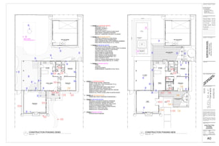
PHASE 1.1 (DETAILED QUOTE)
-NEW BATH 2 & CL. 2
-REMODEL OF BATH 1
-NEW DOOR TO LC.1
-RELOCATE FRONT DOOR W/ NEW ROOF
-NEW FRONT CONCRETE PATHWAY
-NEW EXT. WINDOWS FOR BATH 2 & DINING
PHASE 1.2 (DETAILED QUOTE)
-ONE NEW WINDOW IN LIVING ROOM
-NEW FRENCH DOOR IN BEDROOM 2
-NEW CONCRETE WALL WITH ADDRESS NUMBERS
-NEW FRONT WOOD DECK W/ CC. STEPS
PHASE 2 (DETAILED QUOTE)
-NEW STEPS FROM LIVING TO DINING
-ENLARGE DOOR OPENING FROM LIVING TO DINING
-TWO NEW WINDOWS IN LIVING ROOM
-EXTEND FIRE PLACE FASCIA
-NEW SLIDER IN LIVING ROOM
-NEW SLIDER IN DINING ROOM
-NEW FRENCH DOOR IN BEDROOM 1
-NEW WINDOWS IN BEDROOM 1 & 2
-NEW CONCRETE PATIO
-NEW CC. STEPS FROM DINING TO PATIO
-NEW BACK WOOD DECK W/ CC. STEPS
PHASE 3 (ROUGH QUOTE)
-POOL
-JACUZZI
-SHALLOW STEPS
-SURROUNDING CONCRETE POOL PATIO
SHALLOW AREA
9'-8" x 4'-6"
FRONT
ENTRY
(E)W.H.
(Under Separate
Permit)
BEDROOM 2
A: 153 sq ft
BEDROOM 1
A: 121 sq ft
KITCHEN
A: 150 sq ft
TWO CAR GARAGE
A: 462 sq ft
CL 1
A: 12 sq ft
LC 1
A: 7 sq ft
CL 2
A: 25 sq ft
BATH 2
A: 47 sq ft
BATH 1
A: 41 sq ft
HALL
A: 43 sq ft
DINING
A: 123 sq ft
LIVING
A: 369 sq ft
FRONT WD.DECK
A: 251 sq ft
C.C. PATIO
A: 369 sq ft
BACK WD.DECK
A: 357 sq ft
1.2
1.1
2
3
1.1
1.1
1.1
1.1
1.1
1.1
1.1
2
2
2
2
2
2
2
2 1.1 1.1
2
2
2
2
1.1
2
2
2 1.2
1.1
2
2
W D
PHASE 1.1 (DETAILED QUOTE)
-ALTER FRONT DOORS / WINDOWS
-DEMO LIV/DIN WALL THAT IS ADJACENT TO CL.
-INFILL EXISTING LC 1,2,3
-BATH 1 RECONFIGURE VANITY AND TOILET
-REMOVING WINDOWS IN BEDROOM 3
-REMOVE PORCH, POST, STEPS AND MTL RAILING
-REMOVE FRONT WALK-WAY
-REMOVE ALL FRONT & SIDE-YARD PLANTER BOXES
PHASE 1.2 (DETAILED QUOTE)
-REMOVING FRONT WINDOWS IN BEDROOM 2
PHASE 2 (DETAILED QUOTE)
-ENLARGE 2 INTERIOR PASSAGE OPENINGS
-REMOVE INTERIOR LANDING AND STEPS
-REMOVE INTERIOR LANDING BY FIRE-PLACE
-ALTER EXTERIOR DOORS & WINDOWS
-REMOVE CC. STEPS, RAMP & PADS IN PATIO
-REMOVE EXT. PARTITION WALL
-REMOVE EXT. PLANTER BOXES
PHASE 3 (ROUGH QUOTE)
-EXCAVATION AS NEEDED
(E)W.H.
28'-2" x 10'-8"
Under Separate Permit
BEDROOM 3
A: 371 sq ft
BEDROOM 2
A: 153 sq ft
BEDROOM 1
A: 121 sq ft
KITCHEN
A: 150 sq ft
LIVING / DINING
A: 174 sq ft
TWO CAR GARAGE
A: 462 sq ft
HALL
A: 43 sq ft
BATH
A: 37 sq ft
CL 1
A: 12 sq ft
LC 1
A: 7 sq ft
LC 3
A: 4 sq ft
LC 4
A: 6 sq ft
CL 2
A: 13 sq ft
PORCH
A: 79 sq ft
LC2
A: 2 sq ft
SCALE: 3/16" = 1'-0"
2 CONSTRUCTION PHASING NEW
SCALE: 3/16" = 1'-0"
1 CONSTRUCTION PHASING DEMO
CONSTRUCTION
PHASING
DIAGRAMS
3/16" = 1'-0"
THIS
SHEET
IS
NO
T
PART
O
F
PERM
IT
SET
A0
2. GSPublisherVersion 0.0.100.100
SHEET NO:
SHEET TITLE:
JOB NO:
DATE:
SCALE:
All ideas, designs, arrangements and plans indicated or
represented by this drawing are owned by and are
property of SOLRAC DESIGN and were created, evolved,
and developed for use on, and in connection with, the
specified project. None of these ideas, designs,
arrangements, or plans shall be used by or disclosed to
any person, firm, or corporation for the purpose
whatsoever without the written permission of SOLRAC
DESIGN.
Written dimensions on these drawings shall have
precedence over scaled dimensions. Contractors shall
verify and be responsible for all dimensions and
conditions shown by these drawings. Shop details
must be submitted to this office for approval before
proceeding with fabrication.
SEAL / SIGNATURE:
BUILDING DESIGNER:
1209N.FORMOSAAVE.SUITE3
WESTHOLLYWOOD,CA90046
10.07.2016
CARLOSFLOREZ
323.819.7450
047
ENGINEER:
REVISIONS:
13907BurtonStreet
BURTONREMODEL
PanoramaCity,CA91402
PROJECT / LOCATION:
Brandon Marlo &
Levi Chambers
13907 Burton Street
Panorama City, CA 91402
605.682.9768
brandon.a.marlo@gmail.com
PROPERTY OWNER / CLIENT:
CD FINAL / SE SET
03.07.16
PC Submittal
Final Permit
Schematic Design
04.13.16Design Development
10.07.16
S.E. & T24 Set 07.06.16
NN
CONSULTANTS
PROJECT INFORMATION
BRANDON MARLO (605) 682-9768
LEVI CHAMBERS (620) 206-6344
13907 BURTON STREET
PANORAMA CITY, CA 91402
TRACT: TR 14887, MAP REFERENCE: M B 367-34/38
BLOCK: NONE, LOT: 16
2213-011-006
R1-1
2013 CBC, 2011 LABC
1-STORY EXISTING RESIDENTIAL BUILDING
YEAR BUILT / 1950/1951
OCCUPANCY R-3/U
CONSTRUCTION TYPE V-B
(E) 3 BEDROOMS / 1 BATHROOM
(N) 2 BEDROOMS / 2 BATH
INTERIOR MODIFICATION FOR A NEW BATHROOM IN AN
EXISTING RESIDENCE & REMODEL OF THE EXISTING
BATHROOM AND RELOCATION OF ENTRY DOOR.
60' x 107' = 6,418.3 S.F.
1,091 EXISTING RESIDENCE
462 EXISTING DETACHED GARAGE
1,553 S.F. TOTAL NET AREA
PROPERTY OWNERS:
PROJECT ADDRESS:
LEGAL DESCRIPTION:
APN #:
ZONE:
CODE ANALYSIS:
BUILDING
DESCRIPTION:
PROJECT
DESCRIPTION:
LOT SIZE:
BUILDING SIZE:
NET AREA'S:
LIST OF DRAWINGS
ARCHITECTURALBUILDING DESIGNER:
SOLRAC DESIGN
CARLOS FLOREZ
1209 N. FORMOSA AVE. SUITE 3.
W. HOLLYWOOD, CA 90046
323.819.74504
carlos@solrac-design.com
PROJECT INFO / NOTES
GREEN FORMS
DEMO / FLOOR PLAN
RCP / ROOF PLAN
ENLARGE PLAN / ELEVATIONS
ELEVATIONS & SECTION
SCHEDULES
A1
A2
A3
A4
A5
A6
A7
ENERGY FORMS & CAL'S
T24.1
T24.2
STRUCTURAL
S1.0
S1.1
S1.2
S1.3
S2.0
S2.1
S3.0
S3.1
GENERAL NOTES
TYPICAL DETAILS
TYPICAL DETAILS
TYPICAL DETAILS
FOUNDATION PLAN
ROOF FRAMING PLAN
DETAILS
DETAILS
TITLE-24 REPORT
TITLE-24 REPORT
LIVING
DINING
KITCHEN
HALL
LC 1
BEDROOM 1
BATH 1
CL 1
BEDROOM 2
BATH 2
CL 2
369
123
150
43
7
121
41
12
153
47
25
RESIDENCE TOTAL AREA: 1,091 S.F.
GENERAL CONCRACTOR:
T.B.D
(N) FRONT DECK
(N) BACK DECK
(E) C.C. PATIO
251
357
369
EXTERIOR SPACES:
STRUCTURAL ENGINEER:
BE BASSO ENGINEERING
ALEXANDRE BASSO, P.E.
7231 SUMMITROSE ST.
TUJUNGA, CA 91042
818.531.8741
abasso@bassoeng.com
TITLE 24 ENERGY:
TITLE24-CA.com
19126 HAYNES STREET #2
RESEDA, CA 91335
818.288.4361
arash@an-dg.com
26.Contractor shall check and verify size and location of openings for vents, ducts,
plumbing runs, electrical fixtures, etc. with mechanical, electrical, and architectural
drawings, and mechanical and electrical contractors and shall make all changes therewith
as approved by the Designer before framing walls and ceilings. Duct openings in fire
rated walls shall have fire dampers. Seal between ducts and partitions where required.
27.Contractor shall provide all necessary blocking, stiffeners, bracing, framing, hangers,
or other support for all fixtures, equipment, cabinetry, furnishings and all other items
requiring the same.
28.At the time of bid submittal, the Contractor shall advise the Designer (in writing) of any
specified materials or equipment which are either unavailable or will cause a delay in the
construction completion schedule.
29.Immediately upon being awarded the contract, the Contractor shall prepare and
submit to the Designer a construction progress schedule. The construction schedule
shall be continuously updated and posted on the job site at all times.
30.Contractor shall submit 3 copies of required shop drawings, calculations of fabricated
products, all finish materials and 3 copies of manufacturer's catalog sheets, brochures,
color samples, installation instructions, etc. on manufactured products used/or installed in
the project to the Designer before purchase or delivery to the site. All shop drawings shall
be approved by the Designer. The Designer's approval of such drawings shall not relieve
the Contractor of responsibility for errors of any sort pertaining to the shop drawings.
31.The Contractor shall be responsible for replacement or repair of any damage caused
by him or his subcontractors. The Contractor shall be responsible for any damage to
underground utilities encountered in areas where excavations are indicated and shall
repair any such damage at his own expense. Where utility lines must be maintained
under building, they shall be properly sleeved through foundation walls.
32.Contractor shall guarantee all workmanship and materials for one year except where
indicated in various specification sections for a longer period. The guarantee period is
based on the date of completion of the work, as called out herein. After acceptance of the
building, if during the guarantee period any defects or faulty materials are found,
Contractor shall replace and repair them, together with any damage to finish, fixtures,
equipment or furnishings due to defective work, upon notification by the Architect, and at
no additional expense to the Owner. Exception: The roofing subcontractor shall submit a
maintenance agreement, cosigned by the Contractor, to maintain the roofing in a
watertight condition for a period of one year.
33.Contractor shall provide the Owner a list of the heating, cooling, water heating and
lighting systems and features, components and mechanical devices, conservation or
solar devices installed in the building, and instructions on how to use them efficiently.
Sec. 1403(b)1.
34.Contractor shall provide Owner with the original Owner's Manuals and Instructions for
all appliances, special equipment, lighting fixtures, plumbing fixtures, mechanical
equipment, etc. installed in the building compiled in a binder for the Owner's future
reference.
35.Contractor shall provide Owner with a recommended maintenance schedule for
finishes and components of the building that should be attended to regularly, such as
painting of wood and metal, cleaning of gutters, replacing filters in the air conditioner and
furnaces, etc.
BUILDING CODE
GENERAL REQUIREMENTS
1. The construction shall not restrict a five-foot clear and unobstructed access to any
water or power distribution facilities (Power poles, pull-boxes, transformers, vaults,
pumps valves, meters, appurtenances, etc.) or to the location of the hook-up. The
construction shall not be within ten feet of any power lines-whether or not the lines are
located on the property. Failure to comply may cause construction delays and/or
additional expenses.
2. An approved Seismic Gas Shutoff Valve will be installed on the fuel gas line on the
down stream side of the utility meter and be rigidly connected to the exterior of the
building or structure containing the fuel gas piping. (Per Ordinance 170,158) (Includes
Commercial additions and TI work over $10,000.) Separate plumbing permit is
required.
3. Provide ultra flush water closets for all new construction. Existing shower heads and
toilets must be adapted for low water consumption.
4. A copy of the evaluation report and/or conditions of listing shall be made available at
the job site.
FIRE-RESISTANCE RATED CONSTRUCTION
1. Fire blocking must be provided in accordance with Section 717 at the following
locations:
a. In concealed spaces of stud walls and partitions, including furred spaces, at the
ceiling and floor levels.
b. In concealed spaces of stud walls and partitions, including furred spaces, at 10-foot
intervals along the length of the wall.
c. At all interconnections between concealed vertical and horizontal spaces such as
occur at soffits, drop ceilings and cove ceilings.
d. In concealed spaces between stair stringers at the top and bottom of the run and
between studs along and in line with the run of stairs if the wall under the stairs is
unfinished.
e. In openings around vents, pipes, ducts, chimneys, fireplaces and similar openings
which afford a passage of fire at ceiling and floor levels, with noncombustible
materials.
GENERAL REQUIREMENTS
1.These specifications are for '13907 Burton Street, Panorama City, CA 91402'.
2. All applicable provisions of the 2013 edition of the California Building Code and with
2011LA County Amendments shall be adhered to in the construction of this project. It is
the Contractor's responsibility to construct the project as per these codes.
3. Contractor shall comply with current editions of all applicable codes and ordinances.
Contractor shall pay all fees, miscellaneous costs, and obtain and pay for all permits
necessary to complete all work, with the exception of the Building Permit which the
Owner shall pay for prior to the start of work.
4.Contractor shall be responsible for conformance with inspection requirements for the
City of West Hollywood. Where the plans call for on site inspections by professional
engineers, the Contractor shall be responsible for retaining the engineers and securing
their respective written approvals for work in progress.
5.The Contractor shall carry in force all needed insurance, licenses, fees, permits, taxes
as required by law for the duration of the project.
6.The Contractor shall maintain liability insurance to protect himself and hold the Owner
and the Designer harmless from any and all claims for damages, for personal bodily injury
or death, or property damage, during the course of the contract. (Fire insurance shall be
maintained by Owner.)
7.Contractor shall provide sufficient means for protecting existing exposed interior
finishes, new construction and materials from damage by other trades, weather, or
vandals for the course of the project. Contractor shall provide all barricades, fences, and
other items required by local ordinances and codes.
8.All plumbing fixtures, finishes, hardware and miscellaneous items shall be selected and/
or approved by the Owner and Designer unless noted on plans or specifications. "Or
approved equal" means equal approved by Designer.
9.Field samples and mock-ups shall be prepared at the site by the Contractor as specified
in the various sections of the specification. Affected finish work shall not be started until
the Designer has accepted as satisfactory the field samples and/or mock-up in writing.
10.If the Contractor desires to use any other brand or manufacturer of equal quality,
appearance and utility to the product specified, he shall request substitution to the
Designer with specifications and/or samples.
11.The Owner and immediate neighbors, or neighbors to be affected, should be made
aware 24 hours in advance of construction activities that are potentially disruptive. Use of
neighbor's property is expressly forbidden without their permission. Contractor will be
responsible for any and all damage to such property in the event that damage is done.
12.The Owner may order extra work or make changes by altering, adding to, or deducting
from the work. The contract sum shall be adjusted accordingly. Changes or alterations,
etc. shall be approved by the Owner prior to the start of this work.
13.The intent of these documents (i.e. specifications, drawings and schedules) is to
describe the work including all labor, materials, services, equipment, and transportation
necessary for complete and proper execution of the work indicated on the drawings or
reasonably inferred therefrom. Where drawings are in conflict, Contractor is to provide
Owner with most expensive of conflicting versions.
14.The Designer will in no way be responsible for how the work is performed, safety in,
on or about the job site, nor means, methods, or timeliness in the performance of the
work.
15.Shop and field work shall be performed by mechanics, craftsmen, and workers skilled
and experienced in the fabrication and installation of the work involved. All work on this
project shall be performed in accordance with the best accepted practices of the various
trades involved and in accordance with the drawings, reviewed shop drawings, and these
specifications.
16.These construction documents are based on observation and documentation of
existing conditions by the Designer and from documents provided by the Owner. The
Designer makes no claim to the accuracy of such observation. Should the Contractor
encounter field conditions which vary from these construction documents which effect the
intent of these drawings or the contract/subcontract sum, the Designer shall be notified
immediately. The Contractor shall verify dimensions against field conditions. All trades
shall verify at the project site, conditions and measurements related to their work.
17.Contractor shall not scale the drawings. Dimensions on floor plans are shown to
centerline and/or face of stud and to outside of foundation wall unless noted otherwise.
Written notes take precedence over line drawings.
18.Contractor shall notify the Designer immediately for directions in the event that any
unusual conditions not covered by these notes and documents are encountered during
construction.
19.The Contractor shall be responsible for the accuracy of the building lines and levels.
The Contractor shall compare carefully the lines and levels shown on the drawings with
existing levels for the location and construction of the work and shall call the Designer's
attention to any discrepancies before proceeding with the work.
20.Contractor shall insure that cutting, filling, patching, etc. by all trades causes all parts
to come together properly. The connection of adjoining materials shall be executed
according to instruction by Designer only.
21.Trades shall furnish all labor, equipment, materials and services required to perform all
work necessary, indicated, reasonably inferred, or required by any code with jurisdiction
to complete their scope of work for a complete and properly finished job using only new
materials U.N.O. in accordance with the best accepted standards of workmanship. All
items that are to be furnished by Owner are to be installed by Contractor.
22.The Contractor shall have a superintendent at the construction site whenever any
work under this Contract is being performed in order to provide constant supervision.
23.Contractor shall maintain the job site in a neat and safe condition in accordance with
Title 8 of Construction Safety Orders as enforced by the Division of Industrial Safety at all
times throughout the construction period. The Contractor shall, on a weekly basis, clean
up, remove and dispose in a legal manner all debris and waste attributed to the job.
24.Consultant work that is not a part of the contract documents executed by this
agreement has not been coordinated by the Designer. Contractor shall notify the
Designer of any discrepancies that prevent execution of the work covered by these
documents.
25.Contractor shall coordinate with other contractors directly and separately employed by
Owner for timely storage and installation of their product. Only new materials shall be
used unless noted otherwise on drawings. Materials and products shall be delivered to
the building site in original packages. Materials and products shall be stored above
ground on wood blocking in an upright position protected from the elements in a manner
to prevent damage or marring of finish.
13'-37/8"
11'-57/8"
30'10'
PROPERTYLINE107.00'
PROPERTY LINE 60.00'
PROPERTYLINE107.00'
10'MIN.
(E) WALKWAY
(E) PARKWAY
PROPERTY LINE 60.00'
JACUZZI
8' x 6'
POOL
9'-8" x 15'-0"
SHALLOW AREA
9'-8" x 4'-6"
FRONT
ENTRY
(N) DECK
(N) DECK
LIVING
DINING
PATIO
KITCHEN
BATH 1
BEDROOM 1
BEDROOM 2
LC1
CL 2
BATH 2
2 CAR GARAGE
BURTON STREET
ALLEY
(Under Separate
Permit)
HALL
CL 1
CL
CL
1
VICINITY MAP
SCALE: 1/8" = 1'-0"2
SITE PLAN
PROJECT INFO.
/ VICINITY MAP &
GENERAL NOTES
A1
AS NOTED
13907 Burton Street
Panorama City, CA 91402
RESIDENCE ADDITION
3. GSPublisherVersion 0.0.100.100
SHEET NO:
SHEET TITLE:
JOB NO:
DATE:
SCALE:
All ideas, designs, arrangements and plans indicated or
represented by this drawing are owned by and are
property of SOLRAC DESIGN and were created, evolved,
and developed for use on, and in connection with, the
specified project. None of these ideas, designs,
arrangements, or plans shall be used by or disclosed to
any person, firm, or corporation for the purpose
whatsoever without the written permission of SOLRAC
DESIGN.
Written dimensions on these drawings shall have
precedence over scaled dimensions. Contractors shall
verify and be responsible for all dimensions and
conditions shown by these drawings. Shop details
must be submitted to this office for approval before
proceeding with fabrication.
SEAL / SIGNATURE:
BUILDING DESIGNER:
1209N.FORMOSAAVE.SUITE3
WESTHOLLYWOOD,CA90046
10.07.2016
CARLOSFLOREZ
323.819.7450
047
ENGINEER:
REVISIONS:
13907BurtonStreet
BURTONREMODEL
PanoramaCity,CA91402
PROJECT / LOCATION:
Brandon Marlo &
Levi Chambers
13907 Burton Street
Panorama City, CA 91402
605.682.9768
brandon.a.marlo@gmail.com
PROPERTY OWNER / CLIENT:
CD FINAL / SE SET
03.07.16
PC Submittal
Final Permit
Schematic Design
04.13.16Design Development
10.07.16
S.E. & T24 Set 07.06.16
[ STORM WATER POLLUTION CONTROL FORM
(2014 Los Angeles Green Building Code) GRN 1
Revised 01 01 2014 Page 1 of 1 www.ladbs.org
Storm Water Pollution Control Requirements for Construction Activities
Minimum Water Quality Protection Requirements for All Construction Projects
The following notes shall be incorporated in the approved set of construction/grading plans and
represents the minimum standards of good housekeeping which must be implemented on all construction
projects.
Construction means constructing, clearing, grading or excavation that result in soil disturbance.
Construction includes structure teardown (demolition). It does not include routine maintenance to maintain
original line and grade, hydraulic capacity, or original purpose of facility; emergency construction activities
required to immediately protect public health and safety; interior remodeling with no outside exposure of
construction material or construction waste to storm water; mechanical permit work; or sign permit work.
(Order No. 01-182, NPDES Permit No. CAS004001 – Part 5: Definitions)
1. Eroded sediments and pollutants shall be retained on site and shall not be transported from the site via
sheet flow, swales, area drains, natural drainage or wind.
2. Stockpiles of earth and other construction-related materials shall be covered and/or protected from being
transported from the site by wind or water.
3. Fuels, oils, solvents and other toxic materials must be stored in accordance with their listing and shall
not contaminate the soil nor the surface waters. All approved toxic storage containers are to be
protected from the weather. Spills must be cleaned up immediately and disposed of properly and shall
not be washed into the drainage system.
4. Non-storm water runoff from equipment and vehicle washing and any other activity shall be contained
on the project site.
5. Excess or waste concrete may not be washed into the public way or any drainage system. Provisions
shall be made to retain concrete waste on-site until it can be appropriately disposed of or recycled.
6. Trash and construction –related solid wastes must be deposited into a covered receptacle to prevent
contamination of storm water and dispersal by wind.
7. Sediments and other materials shall not be tracked from the site by vehicle traffic. The construction
entrance roadways must be stabilized so as to inhibit sediments from being deposited into the
street/public ways. Accidental depositions must be swept up immediately and may not be washed down
by rain or by any other means.
8. Retention basins of sufficient size shall be provided to retain storm water runoff on-site and shall be
properly located to collect all tributary site runoff.
9. Where retention of storm water runoff on-site is not feasible due to site constraints, runoff may be
conveyed to the street and the storm drain system provided that an approved filtering system is installed
and maintained on-site during the construction duration.
FORM
2014 Los Angeles Green Building Code GRN 9
Page 1 of 1
Revised 07-01-2015 www.ladbs.org
MANDATORY REQUIREMENTS CHECKLIST
ADDITIONS AND ALTERATIONS TO RESIDENTIAL BUILDINGS
(COMPLETE AND INCORPORATE THIS FORM INTO THE PLANS)
Project Address: _________________________________ Date: _____________________
ITEM
#
CODE
SECTION
REQUIREMENT
REFERENCE
SHEET
Sheet #
or N/A
COMMENTS
e.g. note #, detail #
or reason for N/A
PLANNING AND DESIGN
1 4.106.2
Storm water drainage and retention during
construction
2 4.106.3 Grading and paving
3 4.106.5 Cool roof for reduction of heat island effect
WATER EFFICIENCY & CONSERVATION
4 4.303.1 Water conserving plumbing fixtures and fittings
5 4.303.1.3.2 Multiple showerheads serving one shower
6 4.304.1 Outdoor potable water use in landscape areas
7 4.304.2 Irrigation controllers
MATERIAL CONSERVATION & RESOURCE EFFICIENCY
8 4.406.1 Rodent proofing
9 4.407.3 Flashing details
10 4.407.4 Material protection
11 4.408.1 Construction waste reduction of at least 50%
12 4.410.1 Operation and maintenance manual
ENVIRONMENTAL QUALITY
13 4.503.1 Fireplaces and woodstoves
14 4.504.1
Covering of duct openings and protection of
mechanical equipment during construction
15 4.504.2 Finish material pollutant control
Adhesives, sealants, caulks
Paints and coatings
Aerosol paints and coatings
Verification
16 4.504.2.1
17 4.504.2.2
18 4.504.2.3
19 4.504.2.4
20 4.504.3 Carpet systems
21 4.504.3.1 Carpet cushion
22 4.504.4 Resilient flooring systems
23 4.504.5 Composite wood products
24 4.505.2.1 Capillary break
25 4.505.3 Moisture content of building materials
26 4.506.1 Bathroom exhaust fans
27 4.507.2 Heating and air-conditioning system design
FORM
GRN 11
Revised 02 28 2014 Page 1 of 1 www.ladbs.org
VOC AND FORMALDEHYDE LIMITS
2014 Los Angeles Green Building Code
(Incorporate this form into the plans)
The tables below are taken from the 2014 Los Angeles Green Building Code
Tables 4.504.1, 4.504.2, 4.504.3, 4.504.5, 5.504.4.1, 5.504.4.2, 5.504.4.3, 5.504.4.5
VOC CONTENT LIMITS FOR ARCHITECTURAL COATINGS
2,3
Grams of VOC per Liter of Coating,
Less Water and Less Exempt Compounds
COATING CATEGORY
2,3
CURRENT LIMIT
Flat coatings 50
Nonflat coatings 100
Nonflat-high gloss coatings 150
Specialty Coatings
Aluminum roof coatings 400
Basement specialty coatings 400
Bituminous roof coatings 50
Bituminous roof primers 350
Bond breakers 350
Concrete curing compounds 350
Concrete/masonry sealers 100
Driveway sealers 50
Dry fog coatings 150
Faux finishing coatings 350
Fire resistive coatings 350
Floor coatings 100
Form-release compounds 250
Graphic arts coatings (sign paints) 500
High temperature coatings 420
Industrial maintenance coatings 250
Low solids coatings
1
120
Magnesite cement coatings 450
Mastic texture coatings 100
Metallic pigmented coatings 500
Multicolor coatings 250
Pretreatment wash primers 420
Primers, sealers, and undercoaters 100
Reactive penetrating sealers 350
Recycled coatings 250
Roof coatings 50
Rust preventative coatings 250
Shellacs
Clear
Opaque
730
550
Specialty primers, sealers and undercoaters 100
Stains 250
Stone consolidants 450
Swimming pool coatings 340
Traffic marking coatings 100
Tub and tile refinish coatings 420
Waterproofing membranes 250
Wood coatings 275
Wood preservatives 350
Zinc-rich primers 340
1.
Grams of VOC per liter of coating, including water and including exempt compounds.
2.
The specified limits remain in effect unless revised limits are listed in subsequent columns in the
table.
3.
Values in this table are derived from those specified by the California Air Resources Board,
Architectural Coatings Suggested Control Measure, February 1, 2008. More information is
available from the Air Resources Board.
FORMALDEHYDE LIMITS
1
Maximum Formaldehyde Emissions in Parts per Million.
PRODUCT
CURRENT
LIMIT
Hardwood plywood veneer core 0.05
Hardwood plywood composite core 0.05
Particleboard 0.09
Medium density fiberboard 0.11
Thin medium density fiberboard
2
0.13
1.
Values in this table are derived from those specified by the California Air Resources Board, Air
Toxics Control Measure for Composite Wood as tested in accordance with ASTM E 1333. For
additional information, see California Code of Regulations, Title 17, Sections 93120 through
93120.12.
2.
Thin medium density fiberboard has a maximum thickness of
5
/16 inches (8 mm).
SEALANT VOC LIMIT
Less Water and Less Exempt Compounds in Grams per Liter
SEALANTS CURRENT VOC LIMIT
Architectural 250
Marine deck 760
Nonmembrane roof 300
Roadway 250
Single-ply roof membrane 450
Other 420
SEALANT PRIMERS
Architectural
Nonporous
Porous
250
775
Modified bituminous 500 500
Marine deck 760
Other 750
Note: For additional information regarding methods to measure the VOC content specified in these
tables, see South Coast Air Quality Management District Rule 1168.
ADHESIVE VOC LIMIT
1,2
Less Water and Less Exempt Compounds in Grams per Liter
ARCHITECTURAL APPLICATIONS CURRENT VOC LIMIT
Indoor carpet adhesives 50
Carpet pad adhesives 50
Outdoor carpet adhesives 150
Wood flooring adhesive 100
Rubber floor adhesives 60
Subfloor adhesives 50
Ceramic tile adhesives 65
VCT and asphalt tile adhesives 50
Drywall and panel adhesives 50
Cove base adhesives 50
Multipurpose construction adhesives 70
Structural glazing adhesives 100
Single-ply roof membrane adhesives 250
Other adhesives not specifically listed 50
SPECIALTY APPLICATIONS
PVC welding 510
CPVC welding 490
ABS welding 325
Plastic cement welding 250
Adhesive primer for plastic 550
Contact adhesive 80
Special purpose contact adhesive 250
Structural wood member adhesive 140
Top and trim adhesive 250
SUBSTRATE SPECIFIC APPLICATIONS
Metal to metal 30
Plastic foams 50
Porous material (except wood) 50
Wood 30
Fiberglass 80
1.
If an adhesive is used to bond dissimilar substrates together, the adhesive with the highest VOC
content shall be allowed.
2.
For additional information regarding methods to measure the VOC content specified in this table,
see South Coast Air Quality Management District Rule 1168,
http://www.arb.ca.gov/DRDB/SC/CURHTML/R1168.PDF.
FORM
2014 Los Angeles Green Building Code GRN 14
Revised 1-9-2015 Page 1 of 1 www.ladbs.org
GREEN BUILDING CODE PLAN CHECK NOTES
RESIDENTIAL BUILDINGS
1. For each new dwelling and townhouse, provide a minimum 1-inch
diameter listed raceway that can accommodate a dedicated 208/240 volt
branch circuit. The panel or subpanel shall have sufficient capacity to
support at least Level 2 EVSE. A label stating “EV CAPABLE” shall be
posted in a conspicuous place at the service panel or subpanel and next
to the raceway termination point. (4.106.4.1)
2. EV spaces within the common parking area serving R-occupancies, shall
have labels posted stating “EV CAPABLE” at both the EV charging
space and at a conspicuous place at the service panel or subpanel. The
electrical system shall have sufficient capacity to simultaneously charge
all designated EV spaces at full rated amperage based on Level 2 EVSE.
A separate electrical permit is required. (4.106.4.2)
3. Roofs with
3-year solar reflectance of at least 0.63 and a thermal emittance of at
least 0.75. Roofs with slopes > 2:12 shall have an SRI value of at least
16 or both a 3-year solar reflectance of at least 0.20 and a thermal
emittance of at least 0.75. (4.106.5)
4. The required hardscape used to reduce heat island effects shall have a
solar reflectance value of at least 0.30 as determined per ASTM E918 or
ASTM C1549. (4.106.7)
5. The flow rates for all plumbing fixtures shall comply with the maximum
flow rates in Section 4.303.1. (4.303.1)
6. When a shower is served by more than one showerhead, the combined
flow rate of all the showerheads controlled by a single valve shall not
exceed 2.0 gallons per minute at 80psi, or the shower shall be designed
to only allow one showerhead to be in operation at a time. (4.303.1.3.2)
7. Installed automatic irrigation system controllers shall be weather- or
soil-based controllers. (4.304.1)
8. For projects that include landscape work, the Landscape Certification,
Form GRN 12, shall be completed prior to final inspection approval.
(State Assembly Bill No. 1881)
9. Annular spaces around pipes, electric cables, conduits, or other openings
in the building’s envelope at exterior walls shall be protected against the
passage of rodents by closing such openings with cement mortar,
concrete masonry, or metal plates. Piping prone to corrosion shall be
protected in accordance with Section 313.0 of the Los Angeles Plumbing
Code. (4.406.1)
10. Materials delivered to the construction site shall be protected from rain
or other sources of moisture. (4.407.4)
11. Only a City of Los Angeles certified hauler will be used for hauling of
construction waste. (4.408.1)
12. For all new equipment, an Operation and Maintenance Manual
including, at a minimum, the items listed in Section 4.410.1, shall be
completed and placed in the building at the time of final inspection.
(4.410.1)
13. All new gas fireplaces must be direct-vent, sealed combustion type.
Wood burning fireplaces are prohibited per AQMD Rule 445.
(4.503.1, AQMD Rule 445)
14. All duct and other related air distribution component openings shall be
covered with tape, plastic, or sheet metal until the final startup of the
heating, cooling and ventilating equipment. (4.504.1)
15. Architectural paints and coatings, adhesives, caulks and sealants shall
comply with the Volatile Organic Compound (VOC) limits listed in
Tables 4.504.1-4.504.3. (4.504.2.1-4.504.2.3)
16. The VOC Content Verification Checklist, Form GRN 2, shall be
completed and verified prior to final inspection approval. The
manufacturer’s specifications showing VOC content for all applicable
products shall be readily available at the job site and be provided to the
field inspector for verification. (4.504.2.4)
17. All new carpet installed in the building interior shall meet the testing and
product requirements of one of the following:
a. Carpet and Rug Institute’s Green Label Plus Program
b. California Department of Public Health’s Specification 01350
c. NSF/ANSI 140 at the Gold level
d. Scientific Certifications Systems Indoor Advantage™ Gold
(4.504.3)
18. All new carpet cushion installed in the building interior shall meet the
requirements of the Carpet and Rug Institute Green Label program.
(4.504.3.1)
19. 80% of the total area receiving resilient flooring shall comply with one
or more of the following:
a. VOC emission limits defined in the CHPS High Performance
Products Database
b. Products compliant with the CHPS criteria certified under the
Greenguard Children & Schools program
c. Certification under the Resilient Floor Covering Institute (RFCI)
FloorScore program
d. Meet the California Department of Public Health’s Specification
01350
(4.504.4)
20. New hardwood plywood, particle board, and medium density fiberboard
composite wood products used in the building shall meet the
formaldehyde limits listed in Table 4.504.5. (4.504.5)
21. The Formaldehyde Emissions Verification Checklist, Form GRN 3, shall
be completed prior to final inspection approval. The manufacturer’s
specifications showing formaldehyde content for all applicable wood
products shall be readily available at the job site and be provided to the
field inspector for verification. (4.504.5)
22. A 4-inch thick base of ½ inch or larger clean aggregate shall be provided
for proposed slab on grade construction. (4.505.2.1)
23. A vapor barrier shall be provided in direct contact with concrete for
proposed slab on grade construction. (4.505.2.1)
24. Building materials with visible signs of water damage shall not be
installed. Wall and floor framing shall not be enclosed until it is
inspected and found to be satisfactory. (4.505.3)
25. Newly installed bathroom exhaust fans shall be ENERGY STAR
compliant and be ducted to terminate to the outside of the building.
Provide the manufacturer’s cut sheet for verification. (4.506.1)
26. Newly installed bathroom exhaust fans, not functioning as a component
of a whole house ventilation system, must be controlled by a humidistat
which shall be readily accessible. (4.506.1)
27. The heating and air-conditioning systems shall be sized and designed
using ANSI/ACCA Manual J-2004, ANSI/ACCA 29-D-2009 or
ASHRAE handbooks and have their equipment selected in accordance
with ANSI/ACCA 36-S Manual S-2004. (4.507.2)
FORM
GRN 16
Revised 01 01 2014 Page 1 of 1 www.ladbs.org
PLUMBING FIXTURE FLOW RATES
Residential Occupancies
2014 Los Angeles Green Building Code
(Incorporate this form into the plans)
SECTION 4.303.1
FIXTURE FLOW RATES
FIXTURE TYPE MAXIMUM ALLOWABLE FLOW RATE
Showerheads 2 gpm @ 80 psi
Lavatory faucets, residential 1.5 gpm @ 60 psi
1
Lavatory Faucets, nonresidential 0.4 gpm @ 60 psi
2
Kitchen faucets 1.8 gpm @ 60 psi3
Gravity tank type water closets 1.28 gallons/flush
4
Flushometer tank water closets 1.28 gallons/flush
4
Flushometer valve water closets 1.28 gallons/flush
4
Urinals 0.125 gallons/flush
1
Lavatory Faucets shall not have a flow rate less than 0.8 gpm at 20 psi.
2
Kitchen faucets may temporarily increase flow above the maximum rate, but not above 2.2gpm @ 60psi
and must default to a maximum flow rate of 1.8 gpm @ 60psi.
3
Where complying faucets are unavailable, aerators rated at .35 gpm or or other means may be used to
achieve reduction.
4
Includes single and dual flush water closets with an effective flush of 1.28 gallons or less.
Single Flush Toilets - The effective flush volume shall not exceed 1.28 gallons (4.8 liters). The
effective flush volume is the average flush volume when tested in accordance with ASME
A112.19.233.2.
Dual Flush Toilets - The effective flush volume shall not exceed 1.28 gallons (4.8 liters). The
effective flush volume is defined as the composite, average flush volume of two reduced flushes
and one full flush. Flush volumes will be tested in accordance with ASME A112.19.2 and ASME
A112.19.14.
A2
AS NOTED
GREEN FORMS
& NOTES
4. GSPublisherVersion 0.0.100.100
SHEET NO:
SHEET TITLE:
JOB NO:
DATE:
SCALE:
All ideas, designs, arrangements and plans indicated or
represented by this drawing are owned by and are
property of SOLRAC DESIGN and were created, evolved,
and developed for use on, and in connection with, the
specified project. None of these ideas, designs,
arrangements, or plans shall be used by or disclosed to
any person, firm, or corporation for the purpose
whatsoever without the written permission of SOLRAC
DESIGN.
Written dimensions on these drawings shall have
precedence over scaled dimensions. Contractors shall
verify and be responsible for all dimensions and
conditions shown by these drawings. Shop details
must be submitted to this office for approval before
proceeding with fabrication.
SEAL / SIGNATURE:
BUILDING DESIGNER:
1209N.FORMOSAAVE.SUITE3
WESTHOLLYWOOD,CA90046
10.07.2016
CARLOSFLOREZ
323.819.7450
047
ENGINEER:
REVISIONS:
13907BurtonStreet
BURTONREMODEL
PanoramaCity,CA91402
PROJECT / LOCATION:
Brandon Marlo &
Levi Chambers
13907 Burton Street
Panorama City, CA 91402
605.682.9768
brandon.a.marlo@gmail.com
PROPERTY OWNER / CLIENT:
CD FINAL / SE SET
03.07.16
PC Submittal
Final Permit
Schematic Design
04.13.16Design Development
10.07.16
S.E. & T24 Set 07.06.16
REMOVE DOOR
IN-FILL WALL
(REMOVE CC.
PATHS & PAD)
DEMO WALL
W / DOOR
REMOVE CC. STEPS
REMOVE PLANTER BOX
REMOVE PLANTER BOX
REMOVE PORCH W/
POST, ROOF, STEPS
& MTL. RAILING
REMOVE
PLANTER BOX
REMOVE PLANTER BOX
(N) OPENING FOR
(N) DOOR
(N) OPENING FOR
(N) WINDOW
(N) OPENING FOR
(N) WINDOW
(N) OPENING FOR
(N) WINDOW
REMOVE WINDOW
IN-FILL WALL
REMOVE WINDOW
IN-FILL PARTIAL WALL
(N) OPENING FOR
(N) WINDOW
REMOVE WINDOW
IN-FILL WALL
REMOVE WINDOW
IN-FILL WALL
REMOVE WINDOWS / POST
FOR (N) ENTRY DOOR
(N) OPENING FOR
(N) WINDOW
REMOVE LANDING
/ STEPS
REMOVE CC.
LANDING / RAMP
ROOF LINE ABOVE
ROOF LINE ABOVE
REMOVE
PLANTER BOX
REMOVE WALK WAY
REMOVE
PLANTER BOX
(REMOVE
LANDING
EXTEND F.P.
FASCIA
(N) WINDOW
OPENING
ENLARGE OPENING
4'-2.5"(W) x 6'-8"(H)
ENLARGE OPENING
4'-1"(W) x 6'-8"(H)
(N) WINDOW
OPENING
CC. TO REMAIN
IN THIS AREA
(REMOVE CC.
PATHS & PAD)
REMOVE
PARTITION WALL
REMOVE
PLANTER BOX
RELOCATE VANITY
W D
D1D2
D3
D5
D6 D7
D4
D13
D12
D11
D10
D8
D9
E1
E2 E3
(E)W.H.
BEDROOM 3
A: 371 sq ft
BEDROOM 2
A: 153 sq ft
BEDROOM 1
A: 121 sq ft
KITCHEN
A: 150 sq ft
LIVING / DINING
A: 174 sq ft
TWO CAR GARAGE
A: 462 sq ft
HALL
A: 43 sq ft
BATH
A: 37 sq ft
CL 1
A: 12 sq ft
LC 1
A: 7 sq ft
LC 3
A: 4 sq ft
LC 4
A: 6 sq ft
CL 2
A: 13 sq ft
PORCH
A: 79 sq ft
LC2
A: 2 sq ft
NN
2
A6
ABCDF
1
2
3
4
5
E
3
AF
6"13'-97/16"
5'-27/8"
-1.81' F.F.-1.65' F.F.
0" F.F.
0" F.F.
-0.58' F.F.
0" F.F.
0" F.F.
A
A6
3
A6
4
A6
1
A6
(N) C.C. STEPS
(N) C.C. WALL 36" H.
SMOOTH PLASTER
(N) C.C. STEPS
(N) WD. DECK
(N) BUILDING ADDRESS NO.
IN FILL OPENING
IN FILL OPENING
(N) C.C. STEPS.
(N) ROOF ENTRY
EXTEND F.P.
FASCIA
(N) CC. PAVERS
UNDERGROUND
WATER LINE
CONNECTING TO WASHER
(N) C.C. STEPS
IN FILL OPENING
(GRAVEL AREA)
(GRAVEL AREA)
ENLARGE OPENING
4'-2.5"(W) x 6'-8"(H)
ENLARGE OPENING
4'-1"(W) x 6'-8"(H)
(GRAVEL AREA)
(N) F.P. HEARTH
CANTILEVERED
W D
A
B
E
F
O
H I
J
K
LMN
G
E2 E3
03
REFER:
A5 PLAN
(N) MIN. 2%
SLOPE
(E)W.H.
C
D
(N) BUILT-IN (N) BUILT-IN
(E) ISLAND
(N
)M
IN
.2%
SLO
PE
BEDROOM 2
A: 153 sq ft
BEDROOM 1
A: 121 sq ft
KITCHEN
A: 150 sq ft
TWO CAR GARAGE
A: 462 sq ft
CL 1
A: 12 sq ft
LC 1
A: 7 sq ft
CL 2
A: 25 sq ft
BATH 2
A: 47 sq ft
BATH 1
A: 41 sq ft
HALL
A: 43 sq ft
DINING
A: 123 sq ft
LIVING
A: 369 sq ft
FRONT WD.DECK
A: 251 sq ft
C.C. PATIO
A: 369 sq ft
BACK WD.DECK
A: 357 sq ft
(N) WOOD DECK W/ TYP. CC.
FOOTING / POST / FRAMING SUPPORT
PER MANUFACTURE SPEC.
(N) WOOD DECK W/ TYP.
CC. FOOTING / POST
/ FRAMING SUPPORT
PER MANUFACTURE SPEC.
01
02
REFER: A5 PLAN
WALL TYPES
DEMO WALL
EXISTING WALL TO REMAIN
IN-FILL EXISTING 2X4 STUD WALL
NEW INTERIOR 2X4 WD. STUD WALL
SCALE: 1/4" = 1'-0"1
DEMO PLAN
SCALE: 1/4" = 1'-0"2
GROUND FLOOR PLAN
1/4" = 1'-0"
DEMO /
FLOOR PLAN
A3
5. GSPublisherVersion 0.0.100.100
SHEET NO:
SHEET TITLE:
JOB NO:
DATE:
SCALE:
All ideas, designs, arrangements and plans indicated or
represented by this drawing are owned by and are
property of SOLRAC DESIGN and were created, evolved,
and developed for use on, and in connection with, the
specified project. None of these ideas, designs,
arrangements, or plans shall be used by or disclosed to
any person, firm, or corporation for the purpose
whatsoever without the written permission of SOLRAC
DESIGN.
Written dimensions on these drawings shall have
precedence over scaled dimensions. Contractors shall
verify and be responsible for all dimensions and
conditions shown by these drawings. Shop details
must be submitted to this office for approval before
proceeding with fabrication.
SEAL / SIGNATURE:
BUILDING DESIGNER:
1209N.FORMOSAAVE.SUITE3
WESTHOLLYWOOD,CA90046
10.07.2016
CARLOSFLOREZ
323.819.7450
047
ENGINEER:
REVISIONS:
13907BurtonStreet
BURTONREMODEL
PanoramaCity,CA91402
PROJECT / LOCATION:
Brandon Marlo &
Levi Chambers
13907 Burton Street
Panorama City, CA 91402
605.682.9768
brandon.a.marlo@gmail.com
PROPERTY OWNER / CLIENT:
CD FINAL / SE SET
03.07.16
PC Submittal
Final Permit
Schematic Design
04.13.16Design Development
10.07.16
S.E. & T24 Set 07.06.16
F
A
A
F
E
E
E
A
A
8'-61/2"
8'-71/2"
4'-15/8"
2'-51/2"
3'-2"
4'-1"
2'-8"
6'-10"
1'-6"
8'-6"
GFI
GFI GFI
HALL
CL 1
F
F
F
F
F
D
D
C
B
BEDROOM 1
LC 1
BATH 1
CL 2
BATH 2
DINING
LIVING
C.C PATIO
FRONT
WD. DECK
BEDROOM 2
KITCHEN
BACK
WD.DECK
F
F
SENSOR
2'-0"
5'-51/8"
10'-0"4'-41/8"
(N) ENTRY ROOF
(E) ROOF
SLOPE 2:12
(E) ROOF
SLOPE 2:12
(E) ROOF
SLOPE 2:12
(E) ROOF
SLOPE 2:12
(E) ROOF
SLOPE 2:12
(E)ROOF
SLOPE
(E)ROOF
SLOPE
PROPERTYLINE107.00'
PROPERTYLINE107.00'
(E) ROOF
SLOPE 2:12
(N)ROOF
SLOPE4:12
(N)ROOF
SLOPE4:12
LIGHT FIXTURE SCHEDULE
NO. FIXTURE TYPE MANUFACTURER MODEL NO. QTY.
A SURFACE MOUNT INTERIOR (FIXTURE TYPE T.B.D.) 4
B 18" STRIP INTERIOR LED 1
C 36" STRIP INTERIOR LED 1
D IN GROUND EXTERIOR LED 2
E HANGING LIGHT EXTERIOR LED 3
F STEP LIGHT EXTERIOR LED 7
NN
SCALE: 1/4" = 1'-0"1
REFLECTIVE CEILING PLAN
SCALE: 1/4" = 1'-0"2
ROOF FRAMING PLAN
1/4" = 1'-0"
RCP / ROOF
PLAN
A4"FOR REFERENCE ONLY"
6. GSPublisherVersion 0.0.100.100
SHEET NO:
SHEET TITLE:
JOB NO:
DATE:
SCALE:
All ideas, designs, arrangements and plans indicated or
represented by this drawing are owned by and are
property of SOLRAC DESIGN and were created, evolved,
and developed for use on, and in connection with, the
specified project. None of these ideas, designs,
arrangements, or plans shall be used by or disclosed to
any person, firm, or corporation for the purpose
whatsoever without the written permission of SOLRAC
DESIGN.
Written dimensions on these drawings shall have
precedence over scaled dimensions. Contractors shall
verify and be responsible for all dimensions and
conditions shown by these drawings. Shop details
must be submitted to this office for approval before
proceeding with fabrication.
SEAL / SIGNATURE:
BUILDING DESIGNER:
1209N.FORMOSAAVE.SUITE3
WESTHOLLYWOOD,CA90046
10.07.2016
CARLOSFLOREZ
323.819.7450
047
ENGINEER:
REVISIONS:
13907BurtonStreet
BURTONREMODEL
PanoramaCity,CA91402
PROJECT / LOCATION:
Brandon Marlo &
Levi Chambers
13907 Burton Street
Panorama City, CA 91402
605.682.9768
brandon.a.marlo@gmail.com
PROPERTY OWNER / CLIENT:
CD FINAL / SE SET
03.07.16
PC Submittal
Final Permit
Schematic Design
04.13.16Design Development
10.07.16
S.E. & T24 Set 07.06.16
7'-53/8"
51/4"
4'-0"
6'-41/8"
11'-105/8"
2'-10"2'-6"4'-65/8"
2'-0"
73/8"
1'-6"
3'-13/8"
4'-11"
1'-6"
2'-61/8"
3'-10"
51/4"
51/4"
2'-10"3'-13/8"
1'-6"
1'-8"3'-0"
1
2
3
4
REUSE (E) TOILET
24" x 30"
CLR.
24" x 30"
CLR.
BATH 2
BATH 1
CL.2
HALL
LC 1
CL. 1
(E) TUBE TO REMAIN
5
6
7
8
F2
F2
02
01
E3
N
E2
(E) TUBE TO REMAIN
E3
32"
10"16"6"
1'-6"
32"
15"3'-4"
10"16"6"
MIRROR
2' X 3'
3'-2" 3'-2"
10"20"
36"
6'-4"
6"
MIRROR
5' X 3'
W2
1'-6"
36"
20"10"6"
W2
02
15"
8'-0"
3'-10"
W2
L
6"10"20"
36"
W2
RESTROOM FIXTURE SCHEDULE
FIXTURE TYPE MANUFACTURER MODEL NO. QTY.
LAVATORY T.B.D 3
HUNG WALL FAUCET T.B.D 3
TOILET REUSE EXISTING TOILET FOR BACH 1/ BATH 2 T.B.D. 2
MIRROR 2'X3' T.B.D 1
MIRROR 5'X3' T.B.D 1
SHOWER FAUCET T.B.D 1
GLASS SHOWER WALLS / DOOR T.B.D 1
SCALE: 1/2" = 1'-0"0
ENLARGE FLOOR PLAN
SCALE: 1/2" = 1'-0"1
BATH 1 NORTH
SCALE: 1/2" = 1'-0"2
BATH 1 EAST
SCALE: 1/2" = 1'-0"3
BATH 1 SOUTH
SCALE: 1/2" = 1'-0"4
BATH 1 WEST
SCALE: 1/2" = 1'-0"5
BATH 2 NORTH
SCALE: 1/2" = 1'-0"6
BATH 2 EAST
SCALE: 1/2" = 1'-0"7
BATH 2 SOUTH
SCALE: 1/2" = 1'-0"8
BATH 2 WEST 1/2" = 1'-0"
ENLARGE PLAN
/ ELEVATIONS
A5
7. GSPublisherVersion 0.0.100.100
SHEET NO:
SHEET TITLE:
JOB NO:
DATE:
SCALE:
All ideas, designs, arrangements and plans indicated or
represented by this drawing are owned by and are
property of SOLRAC DESIGN and were created, evolved,
and developed for use on, and in connection with, the
specified project. None of these ideas, designs,
arrangements, or plans shall be used by or disclosed to
any person, firm, or corporation for the purpose
whatsoever without the written permission of SOLRAC
DESIGN.
Written dimensions on these drawings shall have
precedence over scaled dimensions. Contractors shall
verify and be responsible for all dimensions and
conditions shown by these drawings. Shop details
must be submitted to this office for approval before
proceeding with fabrication.
SEAL / SIGNATURE:
BUILDING DESIGNER:
1209N.FORMOSAAVE.SUITE3
WESTHOLLYWOOD,CA90046
10.07.2016
CARLOSFLOREZ
323.819.7450
047
ENGINEER:
REVISIONS:
13907BurtonStreet
BURTONREMODEL
PanoramaCity,CA91402
PROJECT / LOCATION:
Brandon Marlo &
Levi Chambers
13907 Burton Street
Panorama City, CA 91402
605.682.9768
brandon.a.marlo@gmail.com
PROPERTY OWNER / CLIENT:
CD FINAL / SE SET
03.07.16
PC Submittal
Final Permit
Schematic Design
04.13.16Design Development
10.07.16
S.E. & T24 Set 07.06.16
69/16"
12" 12"
TYP.
2 4 53
(N) WD. DECK
(N) ROOF
(N) WD. DECK
(N) ENTRANCE
DOOR
(N) C.C. WALL 36" H.
IN-FILL OPENING
A
IJKL
D11D12
D3D4D5
E2
B
13
(N) C.C. STEPS
(N) WOOD DECK
FOR PHASE TWO
(N) SLIDER
IN FILL OPENING
(E) DOOR TO
BE REPLACED
F
G/E1
D8D9
E2
D C
(E)
(E)(E)
N.I.C.
EA F
(N) C.C. STEPS(N) WOOD DECK
(N) 3 PANEL
BI-FOLD SLIDER
IN FILL OPENING
(E) WATER HEATER
E
H
E2
E3
D7 D6
F D C B A
3'-0"
ADDRESS NUMBER
(N) ENTRY ROOF
(N) WD. DECK
OVER CC. FOOTING WALL
(N) C.C. STEPS (N) C.C. WALL 36" H.
IN FILL OPENING
D13D2 D1
N
M
O
SCALE: 1/4" = 1'-0"A
CC. STEP DETAIL
SCALE: 1/4" = 1'-0"4
RIGHT/EAST ELEVATION
SCALE: 1/4" = 1'-0"3
LEFT/WEST ELEVATION
SCALE: 1/4" = 1'-0"2
BACK/NORTH ELEVATION
SCALE: 1/4" = 1'-0"1
1 FRONT/SOUTH ELEVATION
EXT.
ELEVATIONS
/ DETAIL
A6
1/4" = 1'-0"
8. GSPublisherVersion 0.0.100.100
SHEET NO:
SHEET TITLE:
JOB NO:
DATE:
SCALE:
All ideas, designs, arrangements and plans indicated or
represented by this drawing are owned by and are
property of SOLRAC DESIGN and were created, evolved,
and developed for use on, and in connection with, the
specified project. None of these ideas, designs,
arrangements, or plans shall be used by or disclosed to
any person, firm, or corporation for the purpose
whatsoever without the written permission of SOLRAC
DESIGN.
Written dimensions on these drawings shall have
precedence over scaled dimensions. Contractors shall
verify and be responsible for all dimensions and
conditions shown by these drawings. Shop details
must be submitted to this office for approval before
proceeding with fabrication.
SEAL / SIGNATURE:
BUILDING DESIGNER:
1209N.FORMOSAAVE.SUITE3
WESTHOLLYWOOD,CA90046
10.07.2016
CARLOSFLOREZ
323.819.7450
047
ENGINEER:
REVISIONS:
13907BurtonStreet
BURTONREMODEL
PanoramaCity,CA91402
PROJECT / LOCATION:
Brandon Marlo &
Levi Chambers
13907 Burton Street
Panorama City, CA 91402
605.682.9768
brandon.a.marlo@gmail.com
PROPERTY OWNER / CLIENT:
CD FINAL / SE SET
03.07.16
PC Submittal
Final Permit
Schematic Design
04.13.16Design Development
10.07.16
S.E. & T24 Set 07.06.16
6'-8"
2'-2" 2'-2"
4'-4"
3'-0"
2'-0"
3'-0"
4'-0"
2'-0"
2'-8"
2'-0"
6'-8"
6'-0"
2'-2" 10'-6"
7'-0"
2'-0"
6'-8"
2'-8"
6'-8"
7'-0"
3'-0" 3'-0"
6'-8"
2'-6"
2'-0"5'-0"
10'-6"
6'-8"
EXT. DOOR / WINDOW SCHEDULES (EXIST/NEW)
NO. W / H LOCATION DESCRIPTION / NOTES / MANUFACTURER TYPE
E2 3'-8" x 3'-6" KITCHEN EXISTING TO REMAIN
E3 4'-0" x 2'-0" BATH 1 EXISTING TO REMAIN
A 6'-0" x 7'-0" LIVING MILGARD ENTRY DOUBLE DOOR 1
B 2'-2" x 5'-0" LIVING MILGARD WINDOW 2
C 2'-2" x 5'-0" LIVING MILGARD WINDOW 2
D 2'-2" x 5'-0" LIVING MILGARD WINDOW 2
E 10'-6" x 7'-0" LIVING MILGARD 3 PANEL BI-FOLD 3
F 12'-0" x 6'-8" DINING MILGARD 3 PANEL SLIDER 4
G 2'-8" x 6'-8" KITCHEN (E1) EXISTING DOOR TO BE REPLACED-SAME SIZE 5
H 4'-4" x 6'-8" BEDROOM 1 MILGARD DOUBLE DOOR 6
I 2'-0" x 4'-0" BEDROOM 1 MILGARD WINDOW 7
J 2'-0" x 4'-0" BEDROOM 1 MILGARD WINDOW 7
K 2'-0" x 4'-0" BEDROOM 2 MILGARD WINDOW 7
L 2'-0" x 4'-0" BEDROOM 2 MILGARD WINDOW 7
M 4'-4" x 6'-8" BEDROOM 2 MILGARD DOUBLE DOOR 6
N 2'-0" x 3'-0" BATH 2 MILGARD WINDOW 8
O 2'-0" x 3'-0" DINING MILGARD WINDOW 8
TYPE: 1
ROOM FINISH SCHEDULE (INTERIOR)
ROOM NAME FLOOR COVE BASE WALLS CEILING ROOF
LIVING / ENTRY F1 CB1 W1 R1, R2
DINING F1 CB1 W1
KITCHEN
HALL
LC 1 F1 CB1 W1
BEDROOM 1 F1
BATH 1 F2 CB1 W1 C1
CL 1 F1
BEDROOM 2 F1 CB1 W1
BATH 2 F2 CB1 W2 C1
CL 2 F1 CB1 W1 C1
SAFETY GLAZING NOTES
1.Each pane of safety glazing installed in hazardous locations shall be identified by a manufacturer's designation specifying who applied
the designation, the manufacturer or installer and the safety glazing standard. The following shall be considered specific hazardous
locations for the purposed of safety glazing.
Glazing in: Section 2406
a. Swing doors.
b. Fixed and sliding panels of sliding door assemblies and panels in sliding and bi-fold closet door assemblies.
c. Storm doors.
d. Unframed swinging doors.
e. Doors and enclosures for hot tubs, whirlpools, saunas, steam rooms, bathtubs, and showers.
f. Fixed or operable panels adjacent to a door where the nearest exposed edge of the glazing is within 24" arc of either vertical
edge of the door in a closed position and where the bottom exposed edge of the glazing is less than 60" above the walking
surfaces.
g. Fixed or operable panels, other than described in items e and f, which meets all of the following conditions.
i. Exposed area of an individual pane greater than 9 S.F.
ii. Exposed bottom edge less than 18" above the floor.
iii. Exposed top edge greater than 36" above the floor.
iv. One or more walking surfaces within 36" horizontally of the plane of the glazing.
FINISH SCHEDULE DESCRIPTION (INTERIOR)
NO. MATERIAL / MANUFACTURER
F1 INT. HARDWOOD FLOORING TO REMAIN - (REPLACE / REMATCH / REPAIR IN ALL AFFECTED AREAS)
F2 TILE (DEMOLISH EXISTING HARDWOOD OR TILE AND REPLACE WITH (N) OCTAGON TILE)
CB1 TO MATCH EXIST
W1 GYPSUM BOARD (MATCH EXISTING FINISH AND COLOR, REPAIR OR REFINISH)
W2 SMOOTH PLASTER / CONCRETE FINISH
C1 MATCH EXISTING FINISH AND COLOR, REPAIR OR REFINISH)
NOTE:
F=FLOOR CB=COVE BASE W=WALL C=CEILING R=ROOF
TYPE: 6
TYPE: 4TYPE: 2 TYPE: 3
TYPE: 8
ROOM FINISH SCHEDULE (EXTERIOR)
ROOM NAME FLOOR WALLS
FRONT DECK F3 W3
BACK DECK F3 W3
C.C. PATIO F4 W3
EXT. DOOR / WINDOW SCHEDULES (DEMO)
NO. W / H LOCATION DESCRIPTION / NOTES
D1 3'-0" x 6'-8" DINING DOOR TO BE REMOVED / FOR (N) WINDOW OR WALL IN-FILL
D2 3'-0" x 3'-6" DINING WINDOW TO BE REMOVED
D3 4'-0" x 2'-0" LIVING WINDOW TO BE FILLED IN WITH MATCHING WALL TYPE
D4 6'-0" x 2'-0" LIVING WINDOW TO BE REMOVED / FOR (N) DOOR
D5 4'-0" x 2'-0" LIVING WINDOW TO BE FILLED IN WITH MATCHING WALL TYPE
D6 3'-0" x 6'-8" LIVING DOOR TO BE REMOVED / FILLED IN WITH MATCHING WALL TYPE
D7 7'-4" x 4'-0" LIVING WINDOW TO BE REPLACED (D)
D8 5'-8" x 4'-0" LIVING WINDOW REPLACE WITH SLIDER (E)
D9 5'-8" x 4'-0" LIVING WINDOW REPLACE WITH SLIDER (E)
D10 3'-6" x 4'-0" BEDROOM 1 WINDOW TO BE REPLACED WITH DOOR (F)
D11 3'-6" X 4'-0" BEDROOM 1 WINDOW TO BE FILLED IN WITH MATCHING WALL TYPE
D12 3'-6" X 4'-0" BEDROOM 2 WINDOW TO BE PARTIAL FILLED IN AND REPLACED WITH NEW WINDOW (I)
D13 3'-6" X 4'-0" BEDROOM 2 WINDOW TO BE REPLACED WITH DOUBLE DOOR (K)
INT. DOOR SCHEDULE (NEW)
NO. W / H LOCATION DESCRIPTION
01 2'-0"x 6'-8" CL 2 POCKET DOOR 01
02 2'-6"x 6'-8" BATH 2 POCKET DOOR 02
03 2'-0" x 6'-8" LC 1 DOOR 03
TYPE: 01 TYPE: 02
FINISH SCHEDULE DESCRIPTION (EXTERIOR)
NO. MATERIAL / MANUFACTURER
F3 (N) WOOD DECK
F4 C.C PATIO
W3 EXTERIOR WALL; (MATCH EXISTING FINISH AND COLOR)
R1 EXTERIOR ROOF; (MATCH EXISTING TYPE, FINISH AND COLOR)
R2 (N) ROOF AREA TO SLOPE (4:12) A LOW BUILT-UP ROOF / TO BE "TORCH-DOWN" WATERTIGHT SEAL
E X T E R I O R
I N T E R I O R
TYPE: 7
TYPE: 03
TYPE: 5
SCHEDULES
A7
AS NOTED